box JAGUAR XFR 2010 1.G Manual Online
[x] Cancel search | Manufacturer: JAGUAR, Model Year: 2010, Model line: XFR, Model: JAGUAR XFR 2010 1.GPages: 3039, PDF Size: 58.49 MB
Page 1444 of 3039

DTC Description Possible Cause Action P1707-77 Transfer Case Neutral or
Park/Neutral Indication
Circuit - commanded
position not reachable
Commanded position not
reachable Clear the DTC. Test drive the Vehicle, engaging and
disengaging the parking lock several times. If the DTC
recurs, check parking lock components and replace as
required. If no faulty park lock component is found
Clear DTC and the DTC returns suspect the
Transmission control module. Install a new
Transmission control module as required, refer to the
new module/component installation note at the top of
the DTC Index P2700-07 Transmission Friction
Element A Apply Time
Range/Performance -
Mechanical Failures
Gear Ratio Monitoring.
Mechanical Failures Check and correct oil level. Clear DTC. If code
re-detects suspect Transmission (Gearbox) internal
fault. Install a new Transmission as required, refer to
the new module/component installation note at the top of the DTC Index P2701-07 Transmission Friction
Element B Apply Time
Range/Performance -
Mechanical Failures
Gear Ratio Monitoring.
Mechanical Failures Check and correct oil level. Clear DTC. If code
re-detects suspect Transmission (Gearbox) internal
fault. Install a new Transmission as required, refer to
the new module/component installation note at the top of the DTC Index P2702-07 Transmission Friction
Element C Apply Time
Range/Performance -
Mechanical Failures
Gear Ratio Monitoring.
Mechanical Failures Check and correct oil level. Clear DTC. If code
re-detects suspect Transmission (Gearbox) internal
fault. Install a new Transmission as required, refer to
the new module/component installation note at the top of the DTC Index P2703-07 Transmission Friction
Element D Apply Time
Range/Performance -
Mechanical Failures
Gear Ratio Monitoring.
Mechanical Failures Check and correct oil level. Clear DTC. If code
re-detects suspect Transmission (Gearbox) internal
fault. Install a new Transmission as required, refer to
the new module/component installation note at the top of the DTC Index P2704-07 Transmission Friction
Element E Apply Time
Range/Performance -
Mechanical Failures
Gear Ratio Monitoring.
Mechanical Failures Check and correct oil level. Clear DTC. If code
re-detects suspect Transmission (Gearbox) internal
fault. Install a new Transmission as required, refer to
the new module/component installation note at the top of the DTC Index P2713-04 Pressure Control Solenoid D
- System Internal Failures
System internal failures Suspect the Transmission control module. Install a
new Transmission control module as required, refer to
the new module/component installation note at the top of the DTC Index P2713-48 Pressure Control Solenoid D
- Supervision Software
Failure
Supervision software
failure Suspect the Transmission control module. Install a
new Transmission control module as required, refer to
the new module/component installation note at the top of the DTC Index P2716-22
Pressure Control Solenoid D
Electrical - signal amplitude
> maximum
Pressure Control Solenoid
D Electrical signal
amplitude > maximum Suspect the Transmission control module. Install a
new Transmission control module as required, refer to
the new module/component installation note at the
top of the DTC Index P2716-1A
Pressure Control Solenoid D
Electrical - Circuit Resistance
Below Threshold
Pressure control solenoid
D circuit resistance below
threshold Suspect the Transmission control module. Install a
new Transmission control module as required, refer to
the new module/component installation note at the
top of the DTC Index P2716-1E
Pressure Control Solenoid D
Electrical - Circuit Resistance
Out Of Range
Pressure control solenoid
D circuit resistance out
of range Suspect the Transmission control module. Install a
new Transmission control module as required, refer to
the new module/component installation note at the
top of the DTC Index P2718-14
Pressure Control Solenoid D
Control Circuit / Open -
Circuit Short to Ground or
Open
Pressure control solenoid
D Circuit Short to Ground
or Open Circuit Suspect the Transmission control module. Install a
new Transmission control module as required, refer to
the new module/component installation note at the
top of the DTC Index P2720-11
Pressure Control Solenoid D
Control Circuit Low - Circuit
Short to Ground
Pressure control solenoid
D Circuit Short to Ground Suspect the Transmission control module. Install a
new Transmission control module as required, refer to
the new module/component installation note at the top of the DTC Index P2721-12
Pressure Control Solenoid D
Control Circuit High - Circuit
Short to Battery
Pressure control solenoid
D Circuit Short to Power Suspect the Transmission control module. Install a
new Transmission control module as required, refer to
the new module/component installation note at the top of the DTC Index P2722-04 Pressure Control Solenoid E
- System Internal Failures
Pressure Control Solenoid
E system internal failures Suspect the Transmission control module. Install a
new Transmission control module as required, refer to
the new module/component installation note at the top of the DTC Index
Page 1447 of 3039

DTC Description Possible Cause Action U0103-82
Lost Communication With
Gear Shift Control Module
A-alive / sequence counter
incorrect / not updated
Alive counter fault Check Transmission shift module for stored DTCs.
Check CAN Bus Circuit for fault U0103-83
Lost Communication With
Gear Shift Control Module A
- value of signal protection
calculation incorrect
Checksum fault Check Transmission shift module for stored DTCs.
Check CAN Bus Circuit for fault U0103-87
Lost Communication With
Gear Shift Control Module A
- missing message
CAN Timeout Check Transmission shift module for stored DTCs.
Check CAN Bus Circuit for fault U0122-82
Lost Communication With
Vehicle Dynamics Control
Module - alive / sequence
counter incorrect / not updated
Alive counter fault Check Anti-lock braking system for stored DTCs. Check
CAN Bus Circuit for fault U0122-83
Lost Communication With
Vehicle Dynamics Control
Module - value of signal
protection calculation
incorrect
Checksum fault Check Anti-lock braking system for stored DTCs. Check
CAN Bus Circuit for fault U0122-87
Lost Communication With
Vehicle Dynamics Control
Module - missing message
CAN Timeout Check Anti-lock braking system for stored DTCs. Check
CAN Bus Circuit for fault U0126-00
Lost Communication With
Steering Angle Sensor
Module - no sub type
information
Lost Communication
With Steering Angle
Sensor Module Check Steering angle sensor for stored DTCs. Check
CAN Bus Circuit for fault U0128-87
Lost Communication With
Park Brake Control Module -
missing message
CAN timeout electronic
parking brake module Check Electronic Parking Brake Module for stored DTCs.
Check CAN Bus Circuit for fault U0140-82
Lost Communication With
Body Control Module - alive / sequence counter incorrect / not updated
Alive counter fault Check Central junction box for stored DTCs. Check CAN
Bus Circuit for fault U0140-83
Lost Communication With
Body Control Module - value
of signal protection
calculation incorrect
Checksum fault Check Central junction box for stored DTCs. Check CAN
Bus Circuit for fault U0140-87
Lost Communication With
Body Control Module - missing message
CAN Timeout Check Central junction box for stored DTCs. Check CAN
Bus Circuit for fault U0155-87
Lost Communication With
Instrument Panel Cluster
(Instrument cluster) Control
Module - missing message
CAN timeout instrument
cluster Check Instrument cluster for stored DTCs. Check CAN
Bus Circuit for fault U0300-68
Control Module - event
information
Transmission software
does not match vehicle
network Check Central junction box software level, Check
Transmission control module Software level, Update
software as required using the manufacturer approved
process U0401-08
Invalid Data Received From
Engine control module/PCM
A - Bus Signal Message
Failures
Inaccurate engine speed,
torque information Check Engine control module for stored DTCs, Check
CAN Bus circuit for faults U0401-68
Invalid Data Received from
Engine control module/PCM
A - event information
Inaccurate engine speed,
torque information Check Engine control module for stored DTCs. Check
CAN Bus Circuit for fault U0401-86
Invalid Data Received from
Engine control module/PCM
A - Signal Invalid
Inaccurate engine speed,
torque information Check Engine control module for stored DTCs. Check
CAN Bus Circuit for fault U0404-68
Invalid Data Received from
Gear Shift Control Module A
- event information
Incorrect CAN data
received from
Transmission shift
module Check Transmission Shift Module for stored DTCs.
Refer to Circuit diagrams and check CAN and LIN Bus
for Circuit fault U0404-81
Invalid Data Received from
Gear Shift Control Module A
- Invalid Serial Data
Received
Incorrect LIN data
received from
Transmission shift
module Check Transmission Shift Module for stored DTCs.
Refer to Circuit diagrams and check CAN and LIN Bus
for Circuit fault www.JagDocs.com
Page 1448 of 3039

DTC Description Possible Cause Action U0416-68
Invalid Data Received From
Vehicle Dynamics Control
Module - event information
Event information brake
information Check Engine control module for stored DTCs. Check
CAN Bus Circuit for fault U0422-68
Invalid Data Received From
Body Control Module - event
information
Event information invalid
Power mode information Check Central junction box for stored DTCs. Check CAN
Bus Circuit for fault U101B-87
Lost Communication With
GSM - Multiple Bus-missing
message
Missing message lost
communication with
Transmission Shift
Module (multiple Bus) Check Transmission Shift Module for stored DTCs.
Refer to Circuit diagrams and check CAN and LIN Bus
for Circuit fault U3000-49
Control Module - internal
electronic failure
Internal electronic failure Suspect the Transmission control module. Install a
new Transmission control module as required, refer to
the new module/component installation note at the top of the DTC Index U3000-4B
Control Module - Circuit
resistance above threshold
Internal electronic failure Check and correct oil level. Check hydraulic flow
through oil cooler and pipe circuit for restriction or
blockage. If no restrictions found, suspect the
Transmission control module. Install a new
Transmission control module as required, refer to the
new module/component installation note at the top of
the DTC Index U3000-81
Control Module - invalid
serial data received
Vehicle or Engine type
signal incorrect from BCM
or incorrect Transmission
control module software
installed Reflash the Transmission control module using the
manufacturer approved process U3001-94
Control Module Improper
Shutdown - unexpected
operation
Control Module Improper
Shutdown (voltage
related) Check Engine control module For Power (generator)
faults. Check Power and Ground Circuit and Battery for
fault. Clear DTCs. Road Test. If DTC reoccurs suspect
the Transmission control module. Install a new
Transmission control module as required, refer to the
new module/component installation note at the top of
the DTC Index
Page 1529 of 3039
Published: 11-May-2011
Automatic Transmission/Transaxle External Controls - TDV6 3.0L Diesel /V8 5.0L Petrol/V8 S/C 5.0L Petrol - External Controls - System Operation and
Component Description
Description and Operation
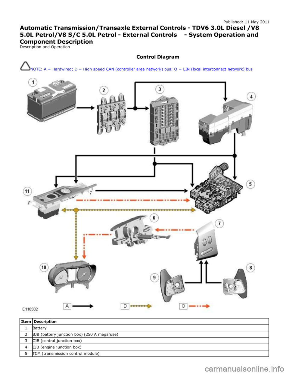
Control Diagram
NOTE: A = Hardwired; D = High speed CAN (controller area network) bus; O = LIN (local interconnect network) bus
Item Description 1 Battery 2 BJB (battery junction box) (250 A megafuse) 3 CJB (central junction box) 4 EJB (engine junction box) 5 TCM (transmission control module)
Page 1533 of 3039
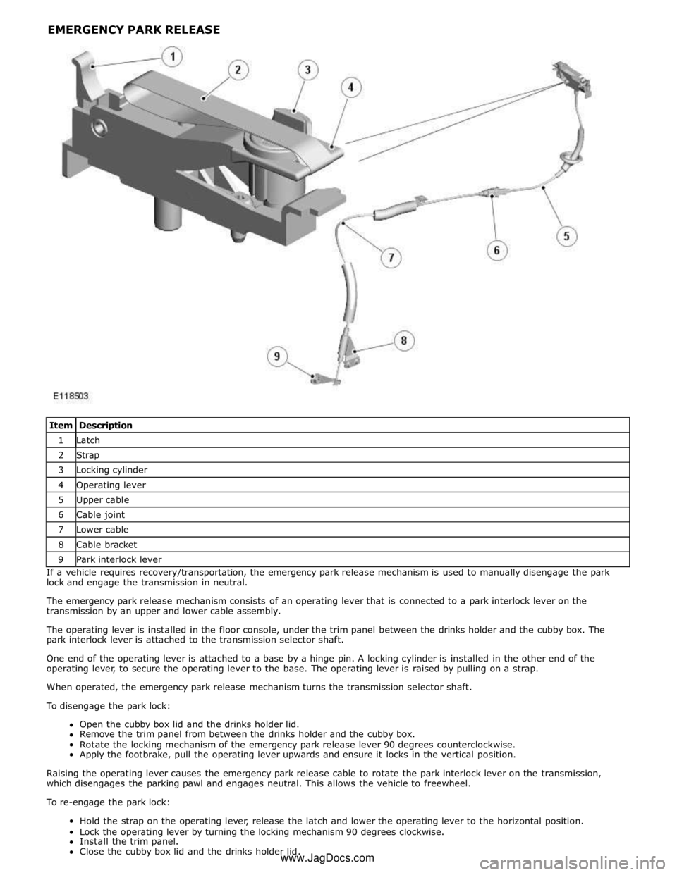
1 Latch 2 Strap 3 Locking cylinder 4 Operating lever 5 Upper cable 6 Cable joint 7 Lower cable 8 Cable bracket 9 Park interlock lever If a vehicle requires recovery/transportation, the emergency park release mechanism is used to manually disengage the park
lock and engage the transmission in neutral.
The emergency park release mechanism consists of an operating lever that is connected to a park interlock lever on the
transmission by an upper and lower cable assembly.
The operating lever is installed in the floor console, under the trim panel between the drinks holder and the cubby box. The
park interlock lever is attached to the transmission selector shaft.
One end of the operating lever is attached to a base by a hinge pin. A locking cylinder is installed in the other end of the
operating lever, to secure the operating lever to the base. The operating lever is raised by pulling on a strap.
When operated, the emergency park release mechanism turns the transmission selector shaft.
To disengage the park lock:
Open the cubby box lid and the drinks holder lid.
Remove the trim panel from between the drinks holder and the cubby box.
Rotate the locking mechanism of the emergency park release lever 90 degrees counterclockwise.
Apply the footbrake, pull the operating lever upwards and ensure it locks in the vertical position.
Raising the operating lever causes the emergency park release cable to rotate the park interlock lever on the transmission,
which disengages the parking pawl and engages neutral. This allows the vehicle to freewheel.
To re-engage the park lock:
Hold the strap on the operating lever, release the latch and lower the operating lever to the horizontal position.
Lock the operating lever by turning the locking mechanism 90 degrees clockwise.
Install the trim panel.
Close the cubby box lid and the drinks holder lid. www.JagDocs.com
Page 1547 of 3039
Published: 28-Apr-2014
Exhaust System - V8 5.0L Petrol/V8 S/C 5.0L Petrol - Exhaust System - System Operation and Component Description
Description and Operation
CATALYTIC CONVERTERS System Operation
In the catalytic converters, the exhaust gases are passed through honeycombed ceramic elements coated with a special
surface treatment called 'washcoat'. The washcoat increases the surface area of the ceramic elements by a factor of
approximately 7000. On top of the washcoat is a coating containing palladium and rhodium, which are the active constituents
for converting harmful emissions into inert by-products. The palladium and rhodium add oxygen to the carbon monoxide and
the hydrocarbons in the exhaust gases, to convert them into carbon dioxide and water respectively.
SEMI-ACTIVE MUFFLER VALVE (5.0L SUPERCHARGER VEHICLES ONLY)
The semi-active muffler valve is operated by the pressure in the exhaust system. At low engine speeds the valve head is
closed or partially closed to provide a more refined noise quality. At higher engine speeds the increased pressure within the
exhaust system opens the valve head to provide a more sporting noise. This is achieved by the valve, which once open, allows
the exhaust gasses to by-pass the baffle tubes and plates in the rear silencer.
Component Description
FRONT SECTION - 4.2L NATURALLY ASPIRATED (NAS ONLY) - From 2010MY
The front section comprises two separate pipes, each incorporating a catalytic converter. Each catalytic converter has a welded
inlet pipe with a flange. The inlet pipe is flared into a cone which mates with the exhaust manifold. The flange has two holes
which locate on studs in the exhaust manifold and is secured with flanged nuts. Each catalytic converter is fitted with a pre
and post catalyst HO2S (heated oxygen sensor).
Each catalytic converter has a curved outlet pipe which mates with the respective inlet pipe for the applicable resonator on the
center section. The joint on each pipe is secured with a clamp.
FRONT SECTION - 5.0L NATURALLY ASPIRATED AND SUPERCHARGER - From 2010MY
The front section is common to both the naturally aspirated and supercharger vehicles. The front section comprises two
separate pipes each incorporating a catalytic converter. Each catalytic converter has a welded pipe with a flange, which is
flared into a cone which mates with the exhaust manifold. Each flange has two holes which locate on studs in the exhaust
manifold and are secured with nuts. Each catalytic converter is fitted with a mid catalyst HO2S. The mid catalyst HO2S is located in the catalytic converter.
NOTE: The pre catalyst HO2S is located in the exhaust manifold.
On vehicles from 2013MY, a post catalyst HO2S is located in the curved pipe from each catalytic converter.
A curved pipe from each catalytic converter locates into the resonator inlet pipes of the center section. The LH (left-hand) pipe
is fitted with a mass damper which absorbs resonance from the system.
REAR SECTION - 4.2L NATURALLY ASPIRATED (NAS ONLY) - From 2010MY
The 2 inlet pipes each connect into a separate resonator silencer. Each resonator silencer is cylindrical in shape and houses 2
perforated tubes separated by 2 baffle plates. Exhaust gasses exit each resonator silencer via an outlet pipe. The 2 outlet
pipes are joined together behind the resonators with a cross over pipe. Each pipe also has a welded hanger bracket which
allow the rear section to be supported on mounting rubbers. A further bracket is welded to each pipe which braces the 2 pipes
together.
The 2 rear silencers each have a welded inlet pipe which mate with the outlet pipes from the resonator silencers and are each
secured with a clamp. The inlet pipes each have a welded hanger bracket which support each rear silencer at the rear of the
vehicle on mounting rubbers. The fabricated rear silencers have 2 perforated tubes which are supported on 2 perforated baffle
plates. The exhaust gasses are expelled from the rear silencer via a single outlet pipe. The outlet pipe from each silencer has
a welded hanger bar which support the rear silencer on mounting rubbers. The outlet pipe is fitted with a welded outlet which
is covered with a polished stainless steel finisher which is part welded to the silencer.
REAR SECTION - 5.0L NATURALLY ASPIRATED - From 2010MY
The 2 pipes from the front section each connect into 2 short pipes on the center resonator box and are secured with clamps.
Two pipes from the resonator box split the system into 2 sections which each connect into another resonator. Each resonator
silencer houses perforated tubes separated by baffle plates. Exhaust gasses exit each resonator silencer via an outlet pipe.
The 2 outlet pipes are joined together behind the resonators with a cross over pipe. Each pipe also has a welded hanger
bracket which allow the rear section to be supported on mounting rubbers. A further bracket is welded to each pipe which
braces the 2 pipes together.
The 2 rear silencers each have a welded inlet pipe which mate with the outlet pipes from the cylindrical resonator silencers and
www.JagDocs.com
Page 1548 of 3039
are each secured with a clamp. The inlet pipes each have a welded hanger bracket which support each rear silencer at the rear
of the vehicle on mounting rubbers. The fabricated rear silencers have 2 perforated tubes which are supported on 2 perforated
baffle plates. The exhaust gasses are expelled from the rear silencer via a single outlet pipe. The outlet pipe from each
silencer has a welded hanger bar which support the rear silencer on mounting rubbers. The outlet pipe is fitted with a welded
outlet which is covered with a polished stainless steel finisher which is part welded to the silencer.
REAR SECTION - 5.0L SUPERCHARGER - From 2010MY
The 2 pipes from the front section each connect into 2 short pipes on the center resonator box and are secured with clamps.
Two pipes from the center resonator box each connect into a second resonator silencer. The resonator silencer comprises
perforated tubes separated by 2 baffle plates. Exhaust gasses exit the resonator silencer via 2 outlet pipes. Each pipe has a
welded hanger bracket which allows the rear section to be supported on mounting rubbers. A further bracket is welded to each
pipe which braces the 2 pipes together.
The 2 rear silencers each have a welded inlet pipe which mate with the outlet pipes from the cylindrical resonator silencers and
are each secured with a clamp. The inlet pipes each have a welded hanger bracket which support each rear silencer at the rear
of the vehicle on mounting rubbers. The fabricated rear silencers have a perforated inlet tube which is supported on 2 baffle
plates. Each rear silencer has a welded hanger bar which supports the rear silencer on mounting rubbers. The outlet pipe is
fitted with a welded twin outlet which is covered with 2 polished stainless steel finishers which are part welded to the silencer.
Semi-Active Muffler Valve
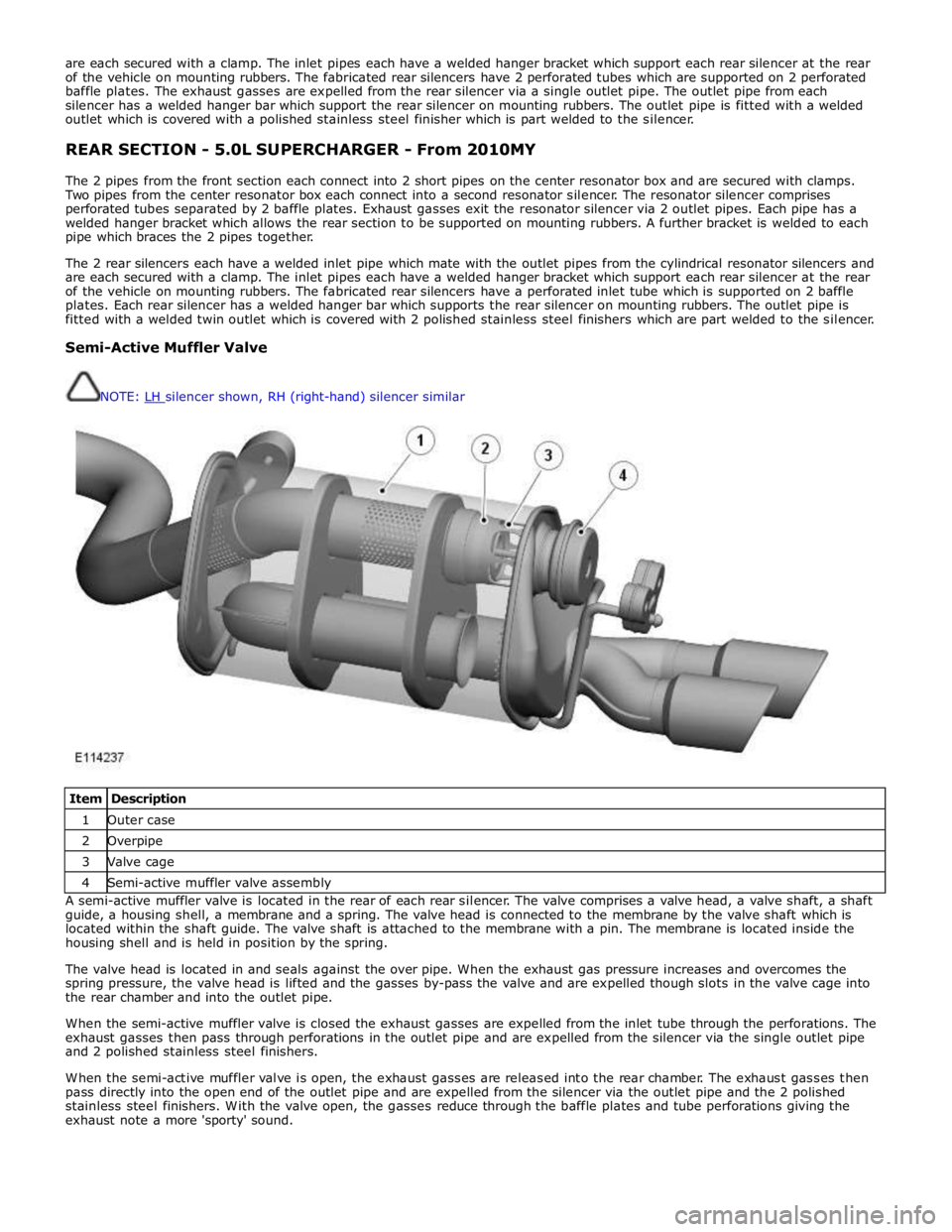
NOTE: LH silencer shown, RH (right-hand) silencer similar
Item Description 1 Outer case 2 Overpipe 3 Valve cage 4 Semi-active muffler valve assembly A semi-active muffler valve is located in the rear of each rear silencer. The valve comprises a valve head, a valve shaft, a shaft
guide, a housing shell, a membrane and a spring. The valve head is connected to the membrane by the valve shaft which is
located within the shaft guide. The valve shaft is attached to the membrane with a pin. The membrane is located inside the
housing shell and is held in position by the spring.
The valve head is located in and seals against the over pipe. When the exhaust gas pressure increases and overcomes the
spring pressure, the valve head is lifted and the gasses by-pass the valve and are expelled though slots in the valve cage into
the rear chamber and into the outlet pipe.
When the semi-active muffler valve is closed the exhaust gasses are expelled from the inlet tube through the perforations. The
exhaust gasses then pass through perforations in the outlet pipe and are expelled from the silencer via the single outlet pipe
and 2 polished stainless steel finishers.
When the semi-active muffler valve is open, the exhaust gasses are released into the rear chamber. The exhaust gasses then
pass directly into the open end of the outlet pipe and are expelled from the silencer via the outlet pipe and the 2 polished
stainless steel finishers. With the valve open, the gasses reduce through the baffle plates and tube perforations giving the
exhaust note a more 'sporty' sound.
Page 1585 of 3039
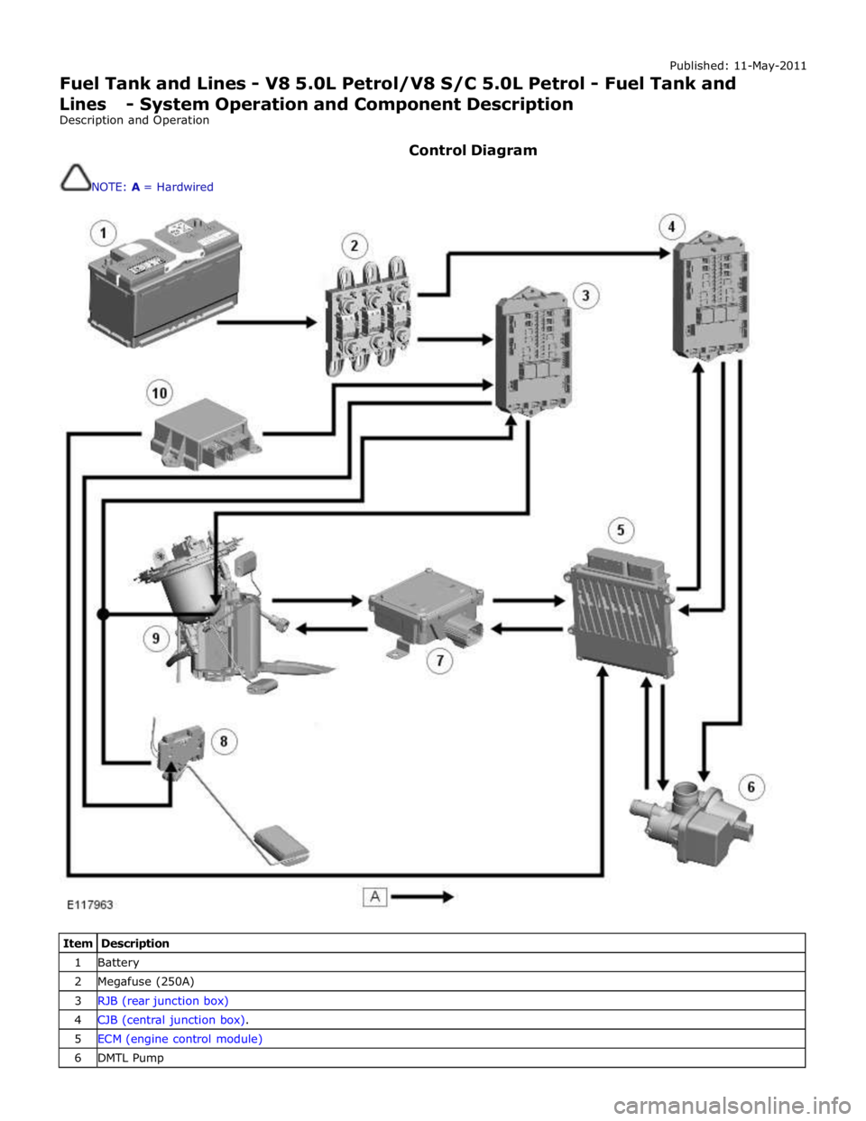
Published: 11-May-2011
Fuel Tank and Lines - V8 5.0L Petrol/V8 S/C 5.0L Petrol - Fuel Tank and Lines - System Operation and Component Description
Description and Operation
Control Diagram
NOTE: A = Hardwired
Item Description 1 Battery 2 Megafuse (250A) 3 RJB (rear junction box) 4 CJB (central junction box). 5 ECM (engine control module) 6 DMTL Pump
Page 1596 of 3039
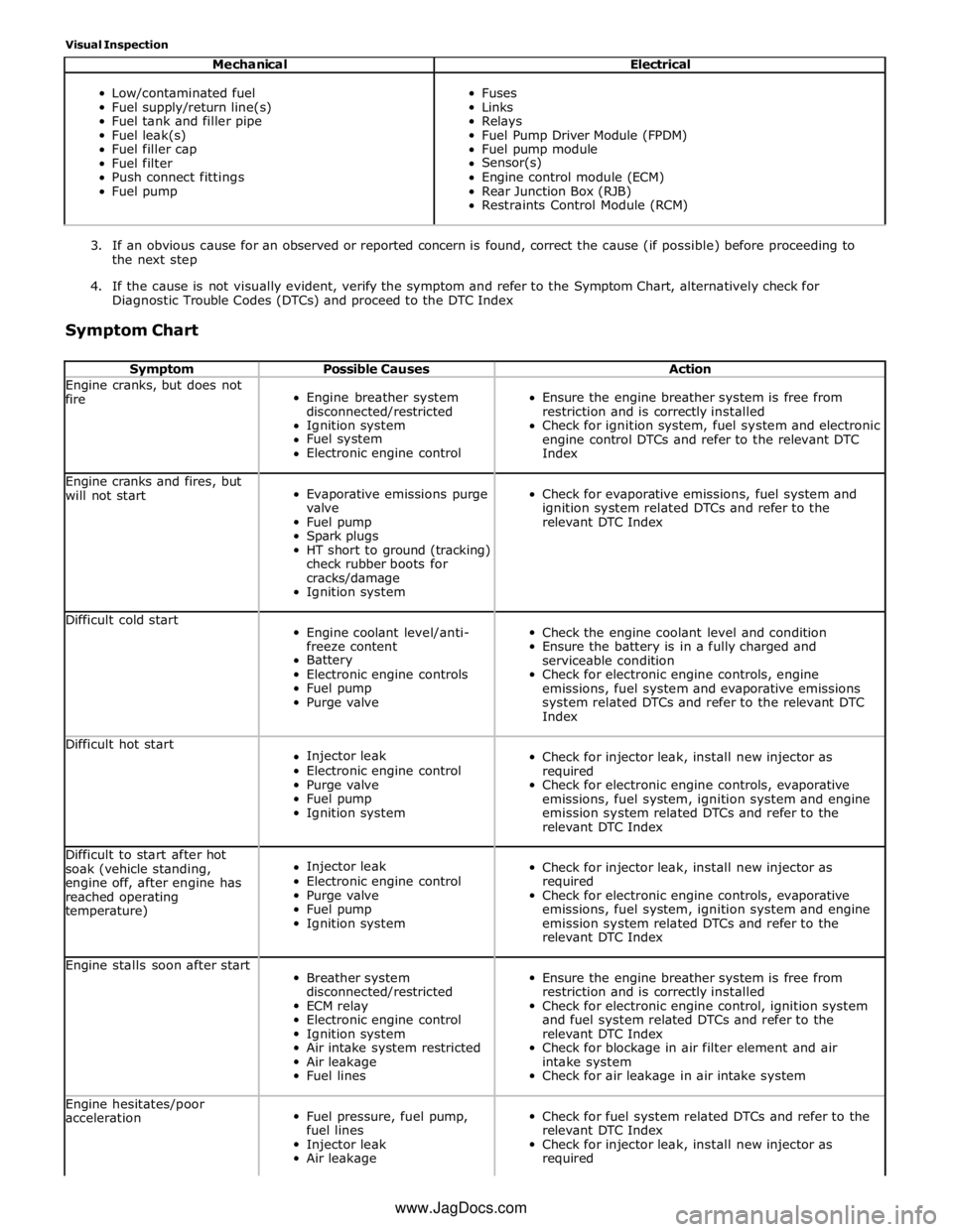
Visual Inspection
Mechanical Electrical
Low/contaminated fuel
Fuel supply/return line(s)
Fuel tank and filler pipe
Fuel leak(s)
Fuel filler cap
Fuel filter
Push connect fittings
Fuel pump
Fuses
Links
Relays
Fuel Pump Driver Module (FPDM)
Fuel pump module
Sensor(s)
Engine control module (ECM)
Rear Junction Box (RJB)
Restraints Control Module (RCM)
3. If an obvious cause for an observed or reported concern is found, correct the cause (if possible) before proceeding to
the next step
4. If the cause is not visually evident, verify the symptom and refer to the Symptom Chart, alternatively check for
Diagnostic Trouble Codes (DTCs) and proceed to the DTC Index
Symptom Chart
Symptom Possible Causes Action Engine cranks, but does not
fire
Engine breather system
disconnected/restricted
Ignition system
Fuel system
Electronic engine control
Ensure the engine breather system is free from
restriction and is correctly installed
Check for ignition system, fuel system and electronic
engine control DTCs and refer to the relevant DTC
Index Engine cranks and fires, but
will not start
Evaporative emissions purge
valve
Fuel pump
Spark plugs
HT short to ground (tracking)
check rubber boots for
cracks/damage
Ignition system
Check for evaporative emissions, fuel system and
ignition system related DTCs and refer to the
relevant DTC Index Difficult cold start
Engine coolant level/anti-
freeze content
Battery
Electronic engine controls
Fuel pump
Purge valve
Check the engine coolant level and condition
Ensure the battery is in a fully charged and
serviceable condition
Check for electronic engine controls, engine
emissions, fuel system and evaporative emissions
system related DTCs and refer to the relevant DTC
Index Difficult hot start
Injector leak
Electronic engine control
Purge valve
Fuel pump
Ignition system
Check for injector leak, install new injector as
required
Check for electronic engine controls, evaporative
emissions, fuel system, ignition system and engine
emission system related DTCs and refer to the
relevant DTC Index Difficult to start after hot
soak (vehicle standing,
engine off, after engine has
reached operating
temperature)
Injector leak
Electronic engine control
Purge valve
Fuel pump
Ignition system
Check for injector leak, install new injector as
required
Check for electronic engine controls, evaporative
emissions, fuel system, ignition system and engine
emission system related DTCs and refer to the
relevant DTC Index Engine stalls soon after start
Breather system
disconnected/restricted
ECM relay
Electronic engine control
Ignition system
Air intake system restricted
Air leakage
Fuel lines
Ensure the engine breather system is free from
restriction and is correctly installed
Check for electronic engine control, ignition system
and fuel system related DTCs and refer to the
relevant DTC Index
Check for blockage in air filter element and air
intake system
Check for air leakage in air intake system Engine hesitates/poor
acceleration
Fuel pressure, fuel pump,
fuel lines
Injector leak
Air leakage
Check for fuel system related DTCs and refer to the
relevant DTC Index
Check for injector leak, install new injector as
required www.JagDocs.com
Page 1686 of 3039
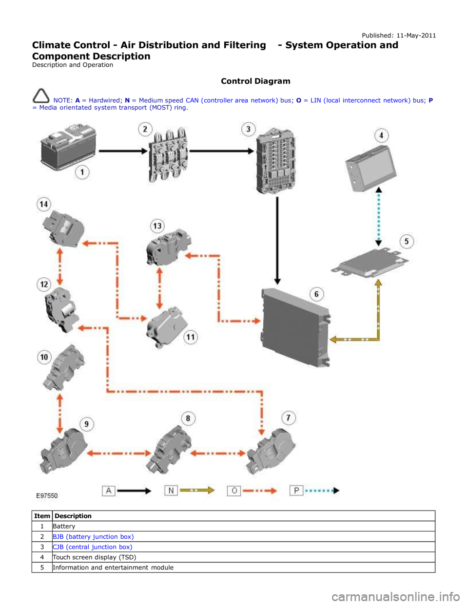
Published: 11-May-2011
Climate Control - Air Distribution and Filtering - System Operation and
Component Description
Description and Operation
Control Diagram
NOTE: A = Hardwired; N = Medium speed CAN (controller area network) bus; O = LIN (local interconnect network) bus; P
= Media orientated system transport (MOST) ring.
Item Description 1 Battery 2 BJB (battery junction box) 3 CJB (central junction box) 4 Touch screen display (TSD) 5 Information and entertainment module