box JAGUAR XFR 2010 1.G Workshop Manual
[x] Cancel search | Manufacturer: JAGUAR, Model Year: 2010, Model line: XFR, Model: JAGUAR XFR 2010 1.GPages: 3039, PDF Size: 58.49 MB
Page 1883 of 3039
first charges the battery to its full condition.
NOTE: If the vehicle is only driven for short periods the charging process could take a number of days to complete.
Once the battery is fully charged, the BMS control module will discharge the battery to approximately 75% of its full state of
charge, but never lower than 12.2 V. The time taken to complete this part of the routine is dependent on the electrical load on
the vehicle.
When the second part of the routine has been successfully completed, the BMS control module will return the battery to its
optimum level of charge. The optimum level of charge will be between 12.6 V and 15 V, depending on battery condition,
temperature and loading.
The BMS control module also monitors the primary battery condition with the engine switched off. If a low voltage condition is
detected the BMS control module can request the infotainment system is switched off to protect battery voltage.
DUAL BATTERY SYSTEM - DUAL BATTERY SYSTEM VEHICLES ONLY
The dual battery system prevents electrical loads on the vehicle being subjected to low voltage levels during an ECO
(stop/start system) engine start. Low voltage can occur due to the power demand of the TSS (Tandem Solenoid Starter) motor
and could result in degraded performance of components and/or system control modules. The GWM contains the software to
control the dual battery system and electrical load management system to ensure that ECO engine starts do not affect other
vehicle systems.
The dual battery system isolates all power supply sensitive electrical components which may be affected by low voltage from
the primary battery due TSS motor operation, and supplies them with power from the secondary battery when an engine start
is in progress.
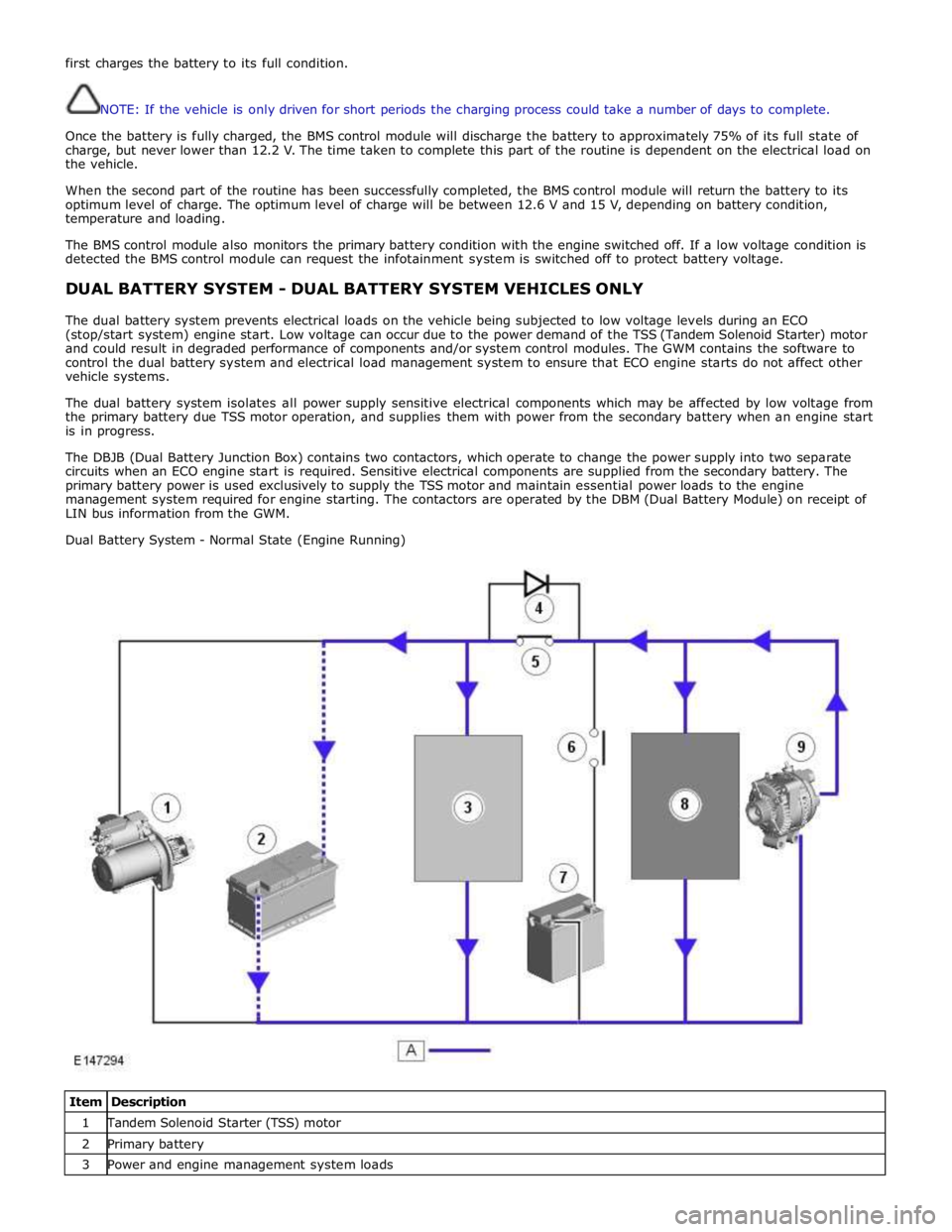
The DBJB (Dual Battery Junction Box) contains two contactors, which operate to change the power supply into two separate
circuits when an ECO engine start is required. Sensitive electrical components are supplied from the secondary battery. The
primary battery power is used exclusively to supply the TSS motor and maintain essential power loads to the engine
management system required for engine starting. The contactors are operated by the DBM (Dual Battery Module) on receipt of
LIN bus information from the GWM.
Dual Battery System - Normal State (Engine Running)
Item Description 1 Tandem Solenoid Starter (TSS) motor 2 Primary battery 3 Power and engine management system loads
Page 1885 of 3039

is operated to crank the engine. The GWM is connected to the ABS (Anti-lock Brake System) control module via the high speed
CAN bus. With the vehicle stationary and the engine off after an ECO engine stop, when the driver releases the brake pedal
the ABS control module senses the reduction in brake pressure. This change of brake pressure state is sent as a high speed
CAN message which is received by the GWM and the ECM. The GWM reacts within 105ms to instruct the DBM via the LIN bus
to operate the two contactors in the DBJB to supply the sensitive loads from the secondary battery and supply the TSS motor
direct from the primary battery.
When the engine is running and the generator is supplying power to the vehicle systems, the GWM again instructs the DBM to
operate the two contactors in the DBJB to supply all vehicle systems from the primary battery and the generator and to isolate
the secondary battery.
Secondary Battery Charging
The DBM also controls the charging of the secondary battery. The GWM contains electrical load management software and
monitors both batteries for their state of charge. The primary battery is monitored by the BMS control module which is
connected to the DBM via the LIN bus. The DBM communicates the primary battery condition to the GWM via a LIN bus
connection. The GWM sends a signal to the DBM via the LIN bus to instruct it to apply charging from the generator to the
secondary battery when required. The contactor 2 is closed by the DBJB to complete the secondary battery circuit, and the
generator output is applied to the secondary battery to charge it.
The generator output is controlled by the GWM which monitors and controls the electrical load management system. The
generator is connected to the GWM by a LIN bus allowing the GWM to control the output of the generator to maintain electrical
system load requirements and battery charging.
Electrical Load Management
The electrical load management is controlled by the GWM and the BMS control module.
The GWM will monitor the vehicle system power loads before and during an ECO engine stop.
Before an ECO engine stop, the GWM will transmit a signal to system control modules on the CAN bus to request a power save
on all electrical loads and set a minimum electrical value override. The GWM monitors the vehicle electrical loads and will
inhibit a ECO engine stop until the load current is at a value low enough to be supported by the secondary battery.
If the electrical loads cannot be reduced sufficiently, the GWM will inhibit the ECO engine stop.
When the engine is stopped after an ECO engine stop, the GWM will continue to monitor the primary battery state of charge.
If the primary or secondary battery voltage falls below 11.0V, a level which will result in degraded starting performance or
possible primary battery damage, the GWM will initiate an engine start.
System Inhibits
The ECO stop/start system is inhibited if the dual battery system is not be capable of preventing electrical loads on the
vehicle being subject to unacceptably low voltage levels during ECO stop/start operations due to a fault.
ECO stop/start inhibit monitoring of the primary battery is performed by the BMS control module. If the primary battery voltage
is too low to support an ECO stop/start, then the BMS control module will send a message to the GWM on the LIN bus to
suspend ECO stop/start.
The GWM monitors the secondary battery and the dual battery system components. Any fault found will cause the GWM to
inhibit ECO stop/start and the GWM will record a DTC (diagnostic trouble code).
Fault Diagnosis
The GWM performs passive and active diagnostics on the dual battery system to determine the status of the system
components.
Passive diagnostics can detect faults in the DBJB and can check for stuck open or closed contactors and failure of DBM
contactor command signals.
Active diagnostics is a routine to test the capability of the contactors to respond to open or close command signals sent from
the GWM to the DBM. This routine also checks the FET's (Field Effect Transistors) activate as required. (Refer to Dual Battery
Junction Box below for description of FET operation)
The GWM will also check the dual battery system components for faults in a controlled environment when the generator is
providing a charging output. This will ensure that the detection of a fault will not result in sensitive electrical loads being
subjected to low voltage which may occur during an ECO stop/start with a fault present.
The GWM will illuminate the charge warning indicator in the instrument cluster if fault is detected in the dual battery system
which will result in a degraded power supply.
If a fault is detected the GWM transmits a CAN message to inhibit ECO stop/start operation. In some cases it will record a
DTC, display a warning message in instrument cluster and also illuminate charge warning indicator.
PRIMARY BATTERY - ALL VEHICLES Component Description
The primary battery is located in a plastic tray under the luggage compartment floor in the right side of the luggage
compartment, adjacent to the spare wheel. The battery is vented via a tube which is connected with a T piece to the vent from
Page 1887 of 3039

DUAL BATTERY MODULE (DBM)
The DBM (dual battery module) is located at the rear of the right wheel arch in the luggage compartment, adjacent to the
GWM (gateway module) and the RJB (rear junction box). The DBM is attached to a bracket, which is attached to a second
bracket secured to the vehicle body.
The DBM is connected by two hardwired connections to the DBJB (dual battery junction box). The DBM uses these two
connections to apply battery voltage to the contactor coils in the DBJB. A LIN bus connection from the GWM passes contactor operation signals to the DBM which operates the contactors as applicable.
The GWM will also instruct the DBM to apply charging to the secondary battery via a LIN bus message. The GWM instructs the
DBM of the charging current required for the secondary battery and the DBM applies the requested stabilized current to the
secondary battery via a dedicated connection direct to the secondary battery.
The DBM diagnoses the coils of the contactors and will report a fault via the LIN bus to the GWM.
The DBM receives a fused power supply from the RJB. www.JagDocs.com
Page 1897 of 3039
NOTES:
BATTERY
CHARGE
If
the
state
of
charge
is
sufficient
this
step
will
not
show.
Go
to
next
step
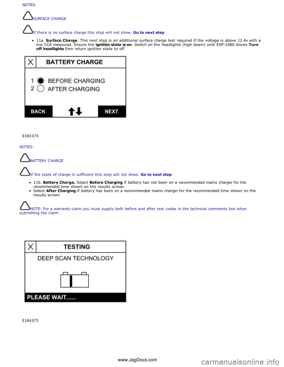
11b.
Battery
Charge.
Select
Before
Charging
if
battery
has
not
been
on
a
recommended
mains
charger
for
the
recommended
time
shown
on
the
results
screen
Select
After
Charging
if
battery
has
been
on
a
recommended
mains
charger
for
the
recommended
time
shown
on
the
results
screen
NOTE:
For
a
warranty
claim
you
must
supply
both
before
and
after
test
codes
in
the
technical
comments
box
when
submitting
the
claim
NOTES:
SURFACECHARGE
Ifthereisnosurfacechargethisstepwillnotshow.Gotonextstep
11a.SurfaceCharge.Thisnextstepisanadditionalsurfacechargetestrequiredifthevoltageisabove12.4vwith a
lowCCAmeasured.Ensuretheignitionstateis on.Switchontheheadlights(highbeam)untilEXP-1080showsTurn
offheadlightsthenreturnignitionstatetooffwww.JagDocs.com
Page 1911 of 3039
Published: 11-May-2011
Generator and Regulator - V8 5.0L Petrol/V8 S/C 5.0L Petrol - Generator - System Operation and Component Description
Description and Operation
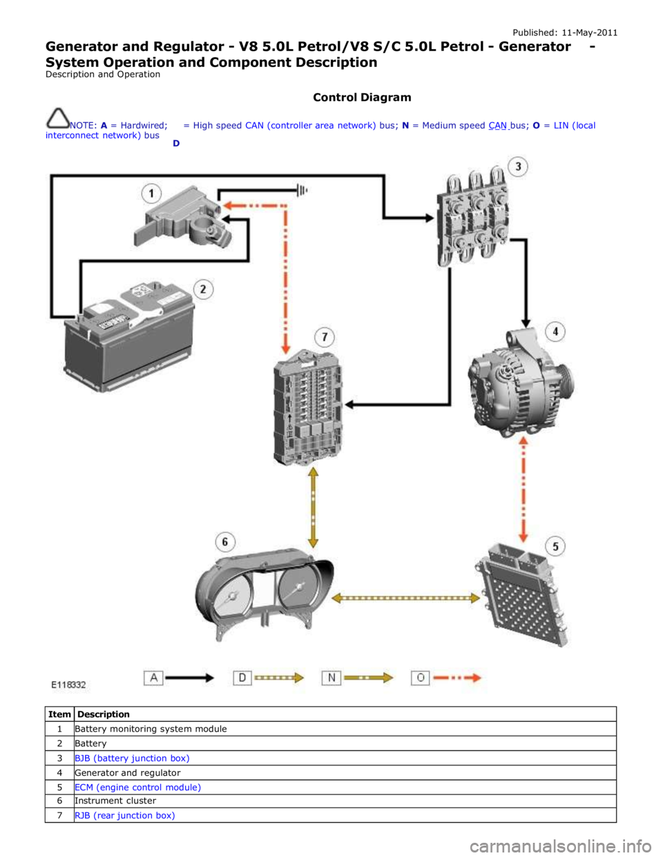
Control Diagram
NOTE: A = Hardwired;
interconnect network) bus
D = High speed CAN (controller area network) bus; N = Medium speed CAN bus; O = LIN (local
Item Description 1 Battery monitoring system module 2 Battery 3 BJB (battery junction box) 4 Generator and regulator 5 ECM (engine control module) 6 Instrument cluster 7 RJB (rear junction box)
Page 1946 of 3039

Published: 11-May-2011
Information and Entertainment System - Audio System - System Operation
and Component Description
Description and Operation
Control Diagram
NOTE: A = Hardwired; N = Medium Speed CAN (controller area network) bus; O = LIN bus; P = MOST ring; T = Coaxial
Item Description 1 Battery 2 BJB (battery junction box) 3 RJB (rear junction box) 4 CJB (central junction box) 5 ICM (information control module) 6 ICP (integrated control panel)
Page 1961 of 3039

1
2
3
4
5
6
7
8
9
10Publi s hed: 11-May-2011
Information and Entertainment System - Speakers - System Operation and
Component Description
Des cript ion and Operat ion
Control Diagram
• NOTE: A = Hardwi red
CONTROL DIAGRAM - JAGUAR SOUND SY STEMItemDescription
Bat tery
BJB (batt ery junct ion box)
RJB (rear junct ion box)
IAM (i nt egrat ed audi o module)
RH (right -hand) rear mid-bass speakerRH rear t weet er s peakerRH front mid-bas s s peakerRH front tweet er s peaker
LH (l eft -hand) front mid-bas s s peakerLH front t weeter s peaker
Page 2023 of 3039
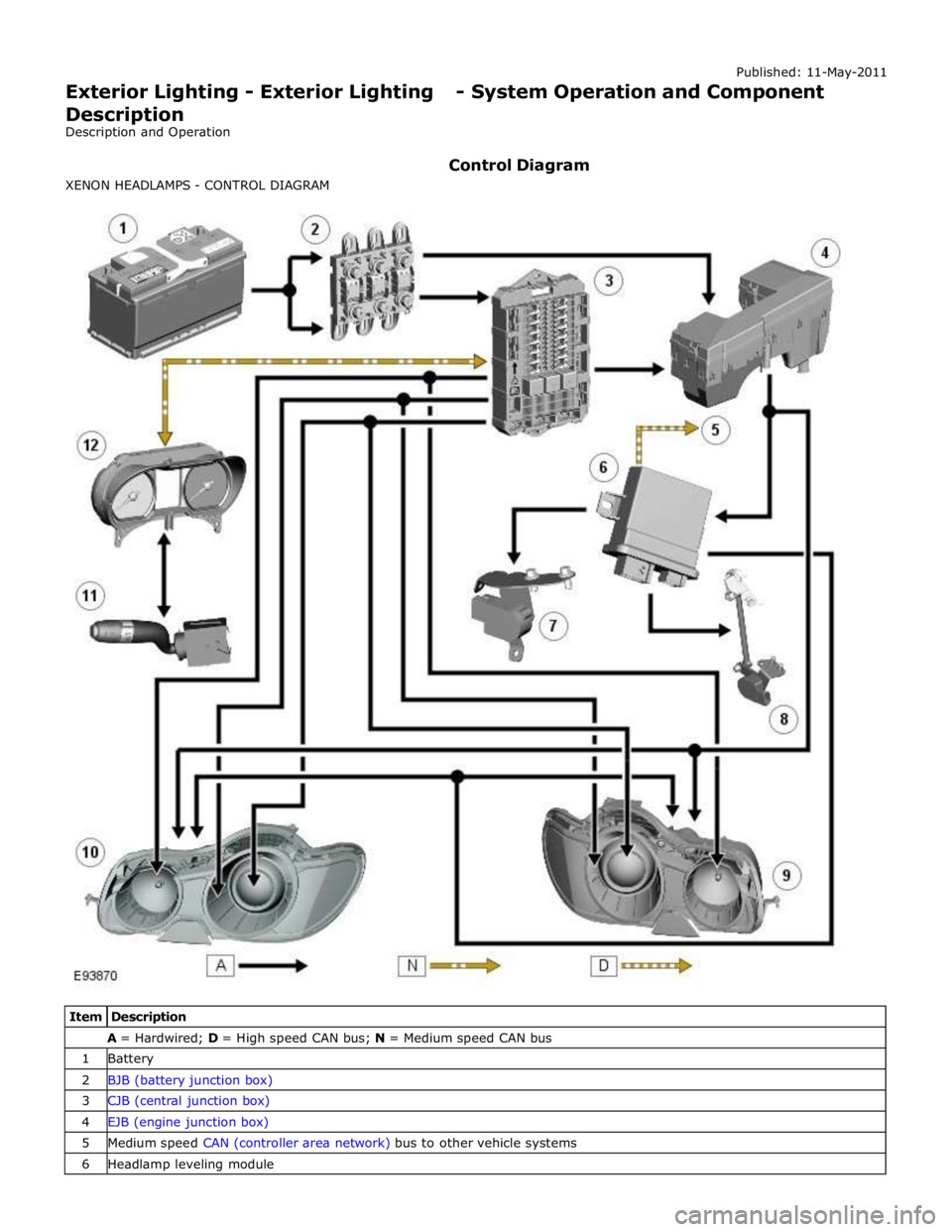
A = Hardwired; D = High speed CAN bus; N = Medium speed CAN bus 1 Battery 2 BJB (battery junction box) 3 CJB (central junction box) 4 EJB (engine junction box) 5 Medium speed CAN (controller area network) bus to other vehicle systems 6 Headlamp leveling module
Page 2025 of 3039
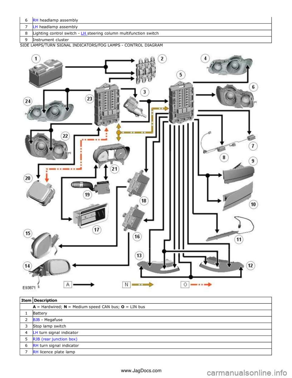
7 LH headlamp assembly 8 Lighting control switch - LH steering column multifunction switch 9 Instrument cluster SIDE LAMPS/TURN SIGNAL INDICATORS/FOG LAMPS - CONTROL DIAGRAM
Item Description A = Hardwired; N = Medium speed CAN bus; O = LIN bus 1 Battery 2 BJB - Megafuse 3 Stop lamp switch 4 LH turn signal indicator 5 RJB (rear junction box) 6 RH turn signal indicator 7 RH licence plate lamp www.JagDocs.com
Page 2026 of 3039

8 LH licence plate lamp 9 LH fog lamp 10 RH fog lamp 11 High mounted stop lamp 12 RH tail lamp assembly 13 LH tail lamp assembly 14 RH door mirror side repeater 15 LH door mirror side repeater 16 RH front door module 17 Auxiliary lighting switch 18 LH front door module 19 Lighting control switch - LH steering column multifunction switch 20 Rain/light sensor 21 Instrument cluster 22 RH headlamp assembly - side lamp and side marker lamp (if fitted) 23 CJB 24 LH headlamp assembly - side lamp and side marker lamp (if fitted)
System Operation CENTRAL JUNCTION BOX (CJB) AND REAR JUNCTION BOX (RJB)
The CJB is an integrated unit which controls body functions and power distribution. The CJB is located on the RH 'A' pillar. The RJB also controls body functions and power distribution and is located in the RH side of the luggage compartment. Central Junction Box
The CJB receives inputs from the following switches via the instrument cluster and the medium speed CAN bus: LH Steering column multifunction switch - Side lamp position
- Headlamp position
- Automatic (AUTO) position
- Timer delay positions
- Turn signal indicators
- Headlamp flash and main beam positions.
The CJB receives direct inputs from the following components: Stop lamp switch
Rain/light sensor.
The CJB provides power supplies to the following lamps:
LH and RH front side lamps LH and RH front side marker lamps (if fitted) LH and RH static bending lamp (if fitted) LH and RH low beam headlamp LH and RH high beam headlamp. Rear Junction Box
The RJB provides power supplies to the following lamps:
LH and RH tail lamps LH and RH stop lamps LH and RH front turn signal indicators LH and RH rear turn signal indicators LH and RH licence plate lamps LH and RH side marker lamps High mounted stop lamp
Rear fog lamps
Reverse lamps.
The RJB also provides a power supply to the LH and RH door modules. The door modules use the power supply to activate the turn signal indicator side repeater lamps located in the door mirrors, on receipt of a medium speed CAN bus message from the RJB. Circuit Protection
The CJB and the RJB provide circuit protection for their respective lighting circuits. The exterior lighting circuits are protected