box JAGUAR XFR 2010 1.G Workshop Manual
[x] Cancel search | Manufacturer: JAGUAR, Model Year: 2010, Model line: XFR, Model: JAGUAR XFR 2010 1.GPages: 3039, PDF Size: 58.49 MB
Page 2034 of 3039

dependant on a particular ignition mode status. The side lamps will also be illuminated when the lighting control switch is in
the AUTO position and a 'lights on' signal is received by the CJB from the rain/light sensor Side Marker Lamps (NAS only)
The side marker lamp is located in the outer part of the headlamp assembly. The side marker lamp uses a W5W wedge fitting
bulb. The bulb is fitted into a holder which connects with contacts in the headlamp housing. The holder is fitted into an
aperture which connects with contacts in the headlamp housing. The side marker lamp is active at all times when the side
lamps are active.
AUTOMATIC HEADLAMP OPERATION
The automatic headlamp function is a driver assistance system. The driver can override the system operation by selection of
side lamp or headlamp on if the ambient light conditions require front and rear lighting to be active. The automatic headlamp
system uses a light sensor and the CJB, which are connected via a LIN (local interconnect network) bus to control the headlamp functionality. The light sensor is incorporated in the rain/light sensor located on the inside of the windshield, below
the rear view mirror. The wiper system also uses the rain/light sensor for automatic wiper operation.
The light sensor measures the ambient light around the vehicle in a vertical direction and also the angular light level from the
front of the vehicle. The rain/light sensor uses vehicle speed signals, wiper switch position and the park position of the front
wipers to control the system. The automatic headlamp operation uses ambient light levels which are monitored by photodiode
incorporated in the rain/light sensor. The rain/light sensor sends a lights on/off request to the CJB on the LIN bus, which responds by switching on the low beam headlamps, front side lamps and rear tail lamps. The automatic headlamps are
activated under the following conditions:
Twilight
Darkness
Rain
Snow
Tunnels
Underground or multistoried car parks.
Operation of the automatic headlamps requires the ignition to be in ignition mode 6, the lighting control switch to be in the
'AUTO' position and a lights on request signal from the light sensor. If the rain sensor signal activates the fast speed wipers,
the low beam headlamps are activated, providing the lighting control switch is in the 'AUTO' position.
HEADLAMP LEVELING
Headlamp leveling provides for the adjustment of the vertical aim of the headlamps. The leveling system is primarily required
to minimise glare to other road users when a heavy load is in the rear of the vehicle. Two systems of headlamp leveling are
available; manual and static dynamic.
Manual Headlamp Leveling
The manual system uses a thumbwheel rheostat to adjust the vertical alignment of the headlamps to compensate for differing
vehicle loading. The rotary thumbwheel is located on the auxiliary lighting switch, adjacent to the illumination dimmer
thumbwheel. Three positions are available to adjust the headlamps to a position to prevent glare to other road users.
Static Dynamic Headlamp Leveling
The static dynamic headlamp leveling system uses the following components:
Front and rear vehicle height sensors
Two headlamp leveling, vertical adjustment motors
Headlamp leveling module
Ignition in mode 6
Vehicle speed information from ABS module.
The static dynamic system uses height sensors fitted to the front and rear suspension and a headlamp leveling module which
periodically monitors the vehicle attitude and adjusts the headlamp vertical alignment accordingly.
Static dynamic headlamp leveling is controlled by a headlamp leveling module located in the lower instrument panel, behind
the glovebox.
The height sensors are both located on the RH side of the vehicle. The front sensor is attached to the front suspension lower arm with a strap and to the front sub frame with a bracket and 2 bolts. The rear sensor is attached to the rear suspension
upper control arm with a cable tied clip and to the rear sub frame with a bracket and 2 bolts. Each sensor has 3 connections to
the headlamp leveling module; power, ground and signal.
DAYTIME RUNNING LAMPS (DRL)
Refer to DRL section for details. Refer to: Daytime Running Lamps (DRL) (417-04 Daytime Running Lamps (DRL), Description and Operation).
REAR LAMP ASSEMBLY
The rear lamp assembly is a 2 piece unit, with one part located in the rear quarter panel and the second part attached to the
luggage compartment lid. The outer rear lamp assembly is located in a recess in the vehicle body. The lamp is secured with 2
studs inboard studs on the lamp body which are secured to the vehicle body with 2 nuts. A third outboard stud and nut secures
Page 2054 of 3039
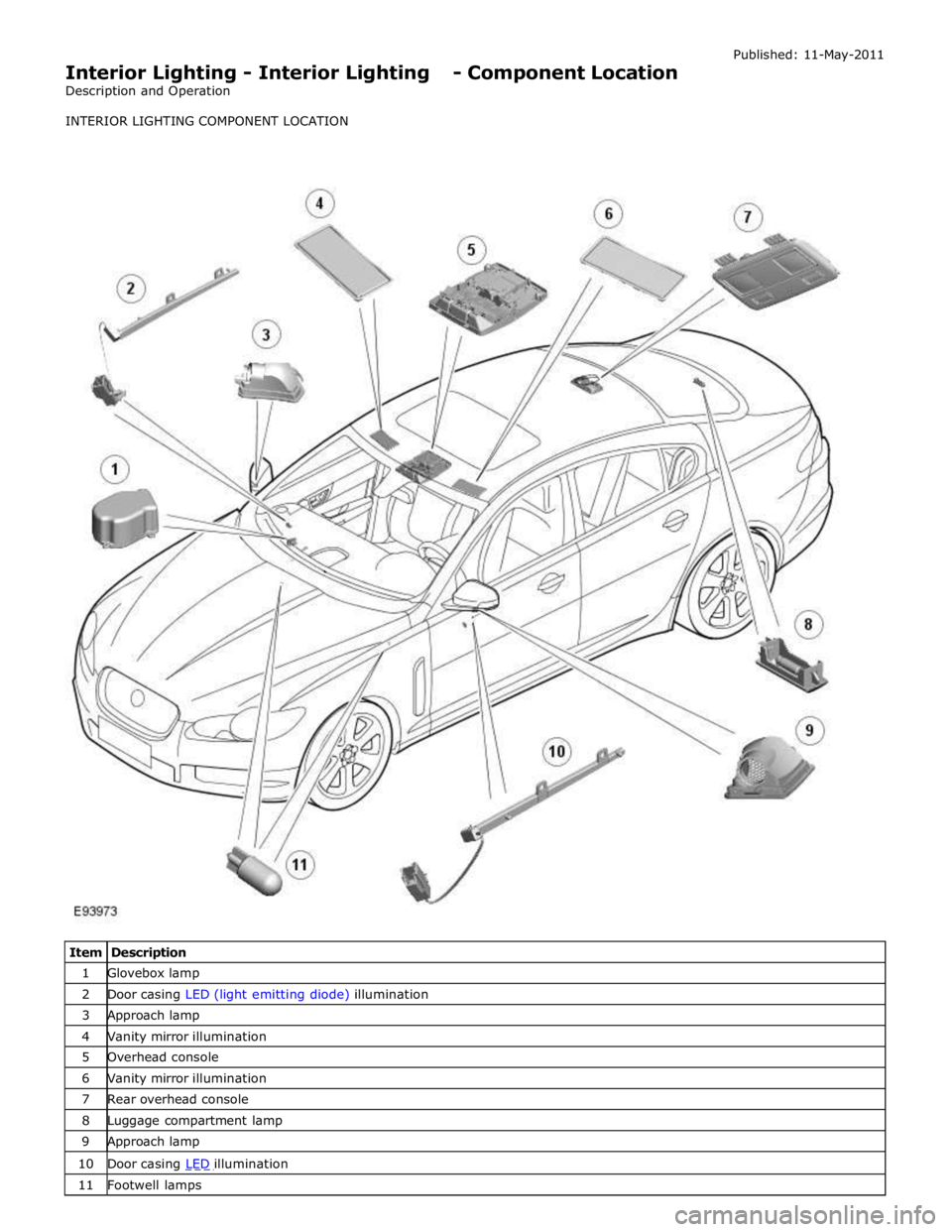
1 Glovebox lamp 2 Door casing LED (light emitting diode) illumination 3 Approach lamp 4 Vanity mirror illumination 5 Overhead console 6 Vanity mirror illumination 7 Rear overhead console 8 Luggage compartment lamp 9 Approach lamp 10 Door casing LED illumination 11 Footwell lamps
Page 2055 of 3039
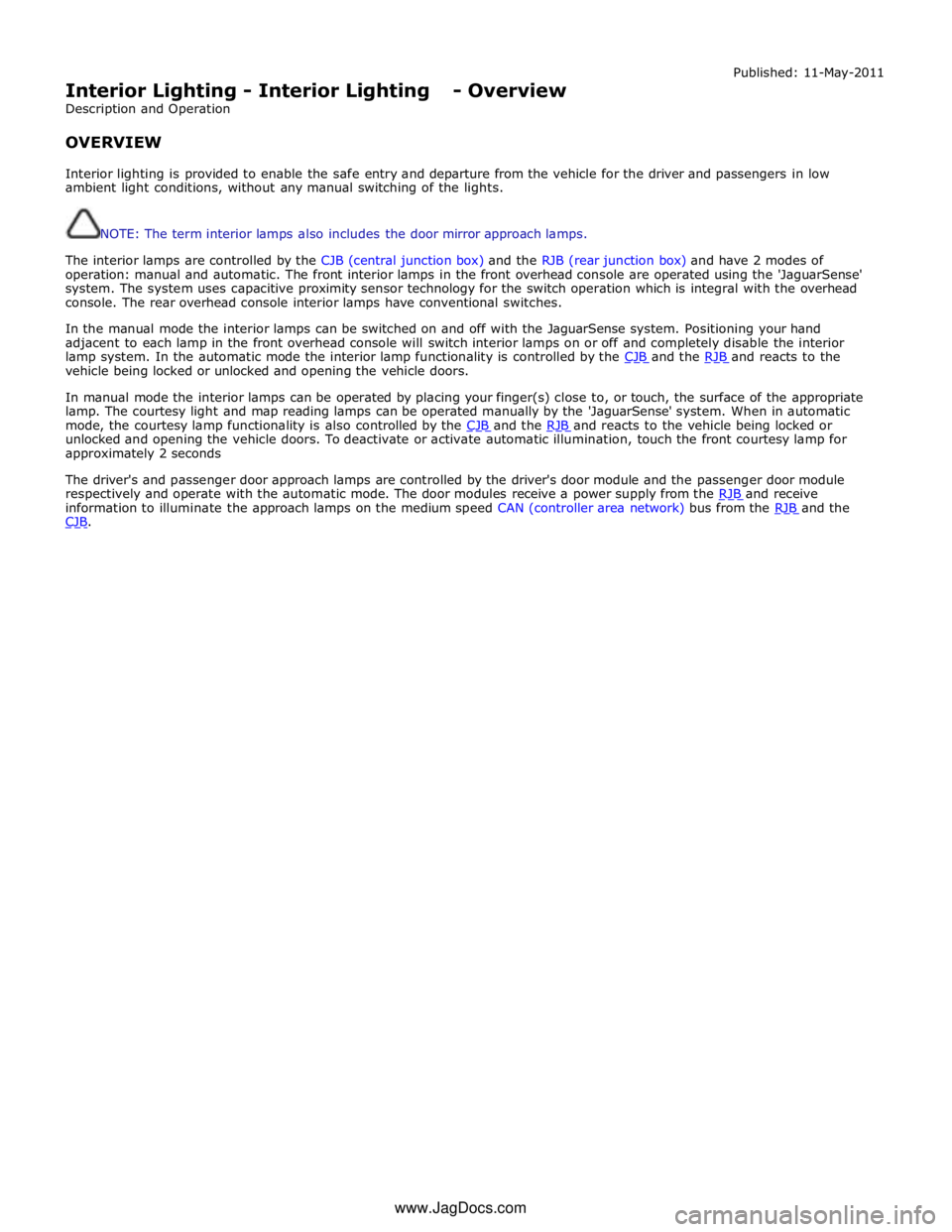
Interior Lighting - Interior Lighting - Overview
Description and Operation
OVERVIEW Published: 11-May-2011
Interior lighting is provided to enable the safe entry and departure from the vehicle for the driver and passengers in low
ambient light conditions, without any manual switching of the lights.
NOTE: The term interior lamps also includes the door mirror approach lamps.
The interior lamps are controlled by the CJB (central junction box) and the RJB (rear junction box) and have 2 modes of
operation: manual and automatic. The front interior lamps in the front overhead console are operated using the 'JaguarSense'
system. The system uses capacitive proximity sensor technology for the switch operation which is integral with the overhead
console. The rear overhead console interior lamps have conventional switches.
In the manual mode the interior lamps can be switched on and off with the JaguarSense system. Positioning your hand
adjacent to each lamp in the front overhead console will switch interior lamps on or off and completely disable the interior
lamp system. In the automatic mode the interior lamp functionality is controlled by the CJB and the RJB and reacts to the vehicle being locked or unlocked and opening the vehicle doors.
In manual mode the interior lamps can be operated by placing your finger(s) close to, or touch, the surface of the appropriate
lamp. The courtesy light and map reading lamps can be operated manually by the 'JaguarSense' system. When in automatic
mode, the courtesy lamp functionality is also controlled by the CJB and the RJB and reacts to the vehicle being locked or unlocked and opening the vehicle doors. To deactivate or activate automatic illumination, touch the front courtesy lamp for
approximately 2 seconds
The driver's and passenger door approach lamps are controlled by the driver's door module and the passenger door module
respectively and operate with the automatic mode. The door modules receive a power supply from the RJB and receive information to illuminate the approach lamps on the medium speed CAN (controller area network) bus from the RJB and the CJB. www.JagDocs.com
Page 2056 of 3039

A = Hardwired; N = Medium speed CAN Bus 1 Battery 2 BJB (battery junction box) - Megafuse 3 BJB - Megafuse 4 RJB (rear junction box) 5 Driver's door mirror approach lamp 6 Driver's door module
Page 2057 of 3039

8 Passenger door module 9 LH (left-hand) rear door latch 10 RH (right-hand) rear door latch 11 LH front door latch 12 RH front door latch 13 CJB (central junction box) 14 LH front door handle LED (light emitting diode) illumination 15 RH front door handle LED illumination CONTROL DIAGRAM (SHEET 2 OF 2)
Item Description A = Hardwired 1 Battery 2 BJB - Megafuse
Page 2058 of 3039
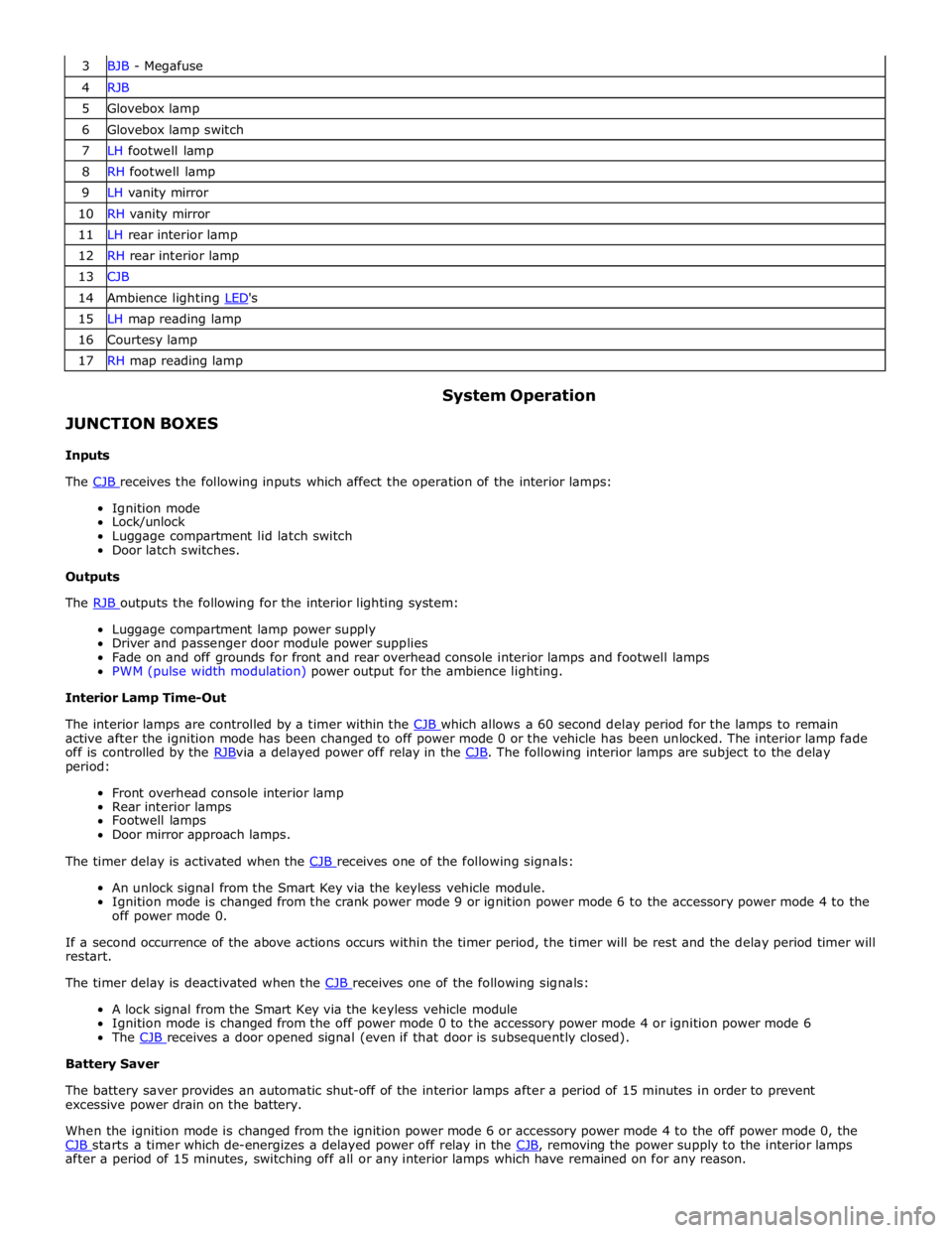
3 BJB - Megafuse 4 RJB 5 Glovebox lamp 6 Glovebox lamp switch 7 LH footwell lamp 8 RH footwell lamp 9 LH vanity mirror 10 RH vanity mirror 11 LH rear interior lamp 12 RH rear interior lamp 13 CJB 14 Ambience lighting LED's 15 LH map reading lamp 16 Courtesy lamp 17 RH map reading lamp
JUNCTION BOXES
Inputs System Operation
The CJB receives the following inputs which affect the operation of the interior lamps: Ignition mode
Lock/unlock
Luggage compartment lid latch switch
Door latch switches.
Outputs
The RJB outputs the following for the interior lighting system: Luggage compartment lamp power supply
Driver and passenger door module power supplies
Fade on and off grounds for front and rear overhead console interior lamps and footwell lamps
PWM (pulse width modulation) power output for the ambience lighting.
Interior Lamp Time-Out
The interior lamps are controlled by a timer within the CJB which allows a 60 second delay period for the lamps to remain active after the ignition mode has been changed to off power mode 0 or the vehicle has been unlocked. The interior lamp fade
off is controlled by the RJBvia a delayed power off relay in the CJB. The following interior lamps are subject to the delay period:
Front overhead console interior lamp
Rear interior lamps
Footwell lamps
Door mirror approach lamps.
The timer delay is activated when the CJB receives one of the following signals: An unlock signal from the Smart Key via the keyless vehicle module.
Ignition mode is changed from the crank power mode 9 or ignition power mode 6 to the accessory power mode 4 to the
off power mode 0.
If a second occurrence of the above actions occurs within the timer period, the timer will be rest and the delay period timer will
restart.
The timer delay is deactivated when the CJB receives one of the following signals: A lock signal from the Smart Key via the keyless vehicle module
Ignition mode is changed from the off power mode 0 to the accessory power mode 4 or ignition power mode 6
The CJB receives a door opened signal (even if that door is subsequently closed). Battery Saver
The battery saver provides an automatic shut-off of the interior lamps after a period of 15 minutes in order to prevent
excessive power drain on the battery.
When the ignition mode is changed from the ignition power mode 6 or accessory power mode 4 to the off power mode 0, the
CJB starts a timer which de-energizes a delayed power off relay in the CJB, removing the power supply to the interior lamps after a period of 15 minutes, switching off all or any interior lamps which have remained on for any reason.
Page 2059 of 3039
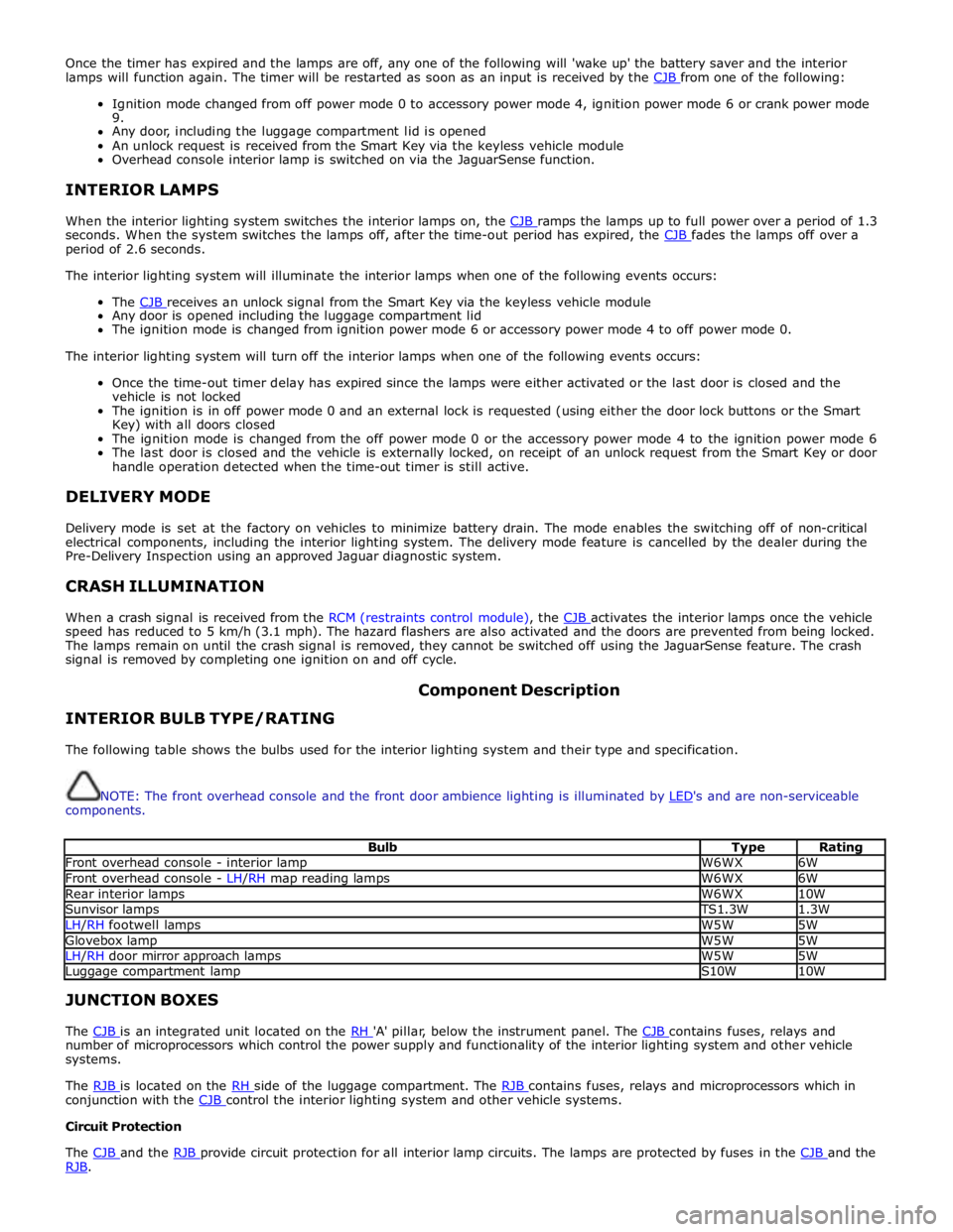
Once the timer has expired and the lamps are off, any one of the following will 'wake up' the battery saver and the interior
lamps will function again. The timer will be restarted as soon as an input is received by the CJB from one of the following:
Ignition mode changed from off power mode 0 to accessory power mode 4, ignition power mode 6 or crank power mode
9.
Any door, including the luggage compartment lid is opened
An unlock request is received from the Smart Key via the keyless vehicle module
Overhead console interior lamp is switched on via the JaguarSense function.
INTERIOR LAMPS
When the interior lighting system switches the interior lamps on, the CJB ramps the lamps up to full power over a period of 1.3 seconds. When the system switches the lamps off, after the time-out period has expired, the CJB fades the lamps off over a period of 2.6 seconds.
The interior lighting system will illuminate the interior lamps when one of the following events occurs:
The CJB receives an unlock signal from the Smart Key via the keyless vehicle module Any door is opened including the luggage compartment lid
The ignition mode is changed from ignition power mode 6 or accessory power mode 4 to off power mode 0.
The interior lighting system will turn off the interior lamps when one of the following events occurs:
Once the time-out timer delay has expired since the lamps were either activated or the last door is closed and the
vehicle is not locked
The ignition is in off power mode 0 and an external lock is requested (using either the door lock buttons or the Smart
Key) with all doors closed
The ignition mode is changed from the off power mode 0 or the accessory power mode 4 to the ignition power mode 6
The last door is closed and the vehicle is externally locked, on receipt of an unlock request from the Smart Key or door
handle operation detected when the time-out timer is still active.
DELIVERY MODE
Delivery mode is set at the factory on vehicles to minimize battery drain. The mode enables the switching off of non-critical
electrical components, including the interior lighting system. The delivery mode feature is cancelled by the dealer during the
Pre-Delivery Inspection using an approved Jaguar diagnostic system.
CRASH ILLUMINATION
When a crash signal is received from the RCM (restraints control module), the CJB activates the interior lamps once the vehicle speed has reduced to 5 km/h (3.1 mph). The hazard flashers are also activated and the doors are prevented from being locked.
The lamps remain on until the crash signal is removed, they cannot be switched off using the JaguarSense feature. The crash
signal is removed by completing one ignition on and off cycle.
INTERIOR BULB TYPE/RATING Component Description
The following table shows the bulbs used for the interior lighting system and their type and specification.
NOTE: The front overhead console and the front door ambience lighting is illuminated by LED's and are non-serviceable components.
Bulb Type Rating Front overhead console - interior lamp W6WX 6W Front overhead console - LH/RH map reading lamps W6WX 6W Rear interior lamps W6WX 10W Sunvisor lamps TS1.3W 1.3W LH/RH footwell lamps W5W 5W Glovebox lamp W5W 5W LH/RH door mirror approach lamps W5W 5W Luggage compartment lamp S10W 10W JUNCTION BOXES
The CJB is an integrated unit located on the RH 'A' pillar, below the instrument panel. The CJB contains fuses, relays and number of microprocessors which control the power supply and functionality of the interior lighting system and other vehicle
systems.
The RJB is located on the RH side of the luggage compartment. The RJB contains fuses, relays and microprocessors which in conjunction with the CJB control the interior lighting system and other vehicle systems. Circuit Protection
The CJB and the RJB provide circuit protection for all interior lamp circuits. The lamps are protected by fuses in the CJB and the RJB.
Page 2061 of 3039
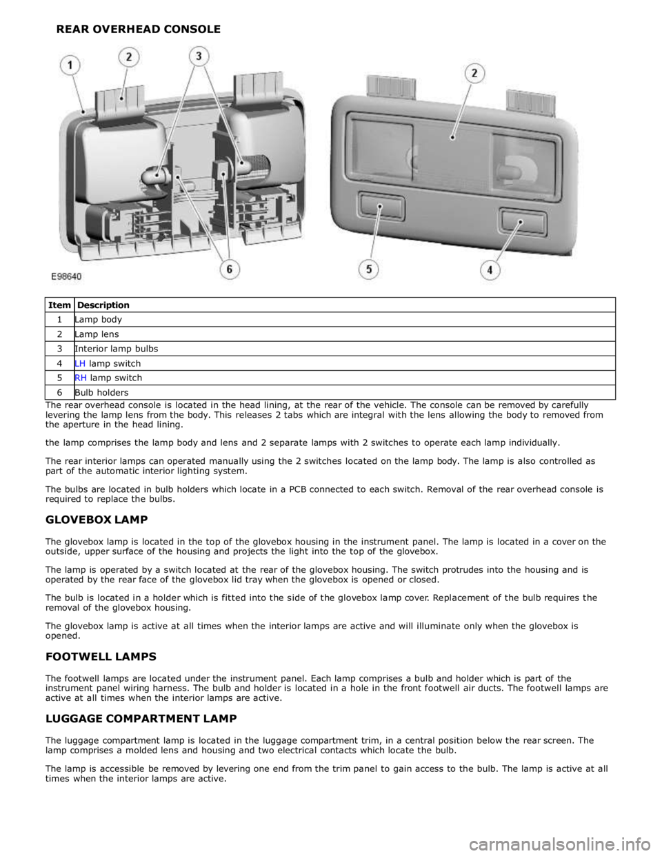
1 Lamp body 2 Lamp lens 3 Interior lamp bulbs 4 LH lamp switch 5 RH lamp switch 6 Bulb holders The rear overhead console is located in the head lining, at the rear of the vehicle. The console can be removed by carefully
levering the lamp lens from the body. This releases 2 tabs which are integral with the lens allowing the body to removed from
the aperture in the head lining.
the lamp comprises the lamp body and lens and 2 separate lamps with 2 switches to operate each lamp individually.
The rear interior lamps can operated manually using the 2 switches located on the lamp body. The lamp is also controlled as
part of the automatic interior lighting system.
The bulbs are located in bulb holders which locate in a PCB connected to each switch. Removal of the rear overhead console is
required to replace the bulbs.
GLOVEBOX LAMP
The glovebox lamp is located in the top of the glovebox housing in the instrument panel. The lamp is located in a cover on the
outside, upper surface of the housing and projects the light into the top of the glovebox.
The lamp is operated by a switch located at the rear of the glovebox housing. The switch protrudes into the housing and is
operated by the rear face of the glovebox lid tray when the glovebox is opened or closed.
The bulb is located in a holder which is fitted into the side of the glovebox lamp cover. Replacement of the bulb requires the
removal of the glovebox housing.
The glovebox lamp is active at all times when the interior lamps are active and will illuminate only when the glovebox is
opened.
FOOTWELL LAMPS
The footwell lamps are located under the instrument panel. Each lamp comprises a bulb and holder which is part of the
instrument panel wiring harness. The bulb and holder is located in a hole in the front footwell air ducts. The footwell lamps are
active at all times when the interior lamps are active.
LUGGAGE COMPARTMENT LAMP
The luggage compartment lamp is located in the luggage compartment trim, in a central position below the rear screen. The
lamp comprises a molded lens and housing and two electrical contacts which locate the bulb.
The lamp is accessible be removed by levering one end from the trim panel to gain access to the bulb. The lamp is active at all
times when the interior lamps are active.
Page 2066 of 3039
Published: 11-May-2011
Daytime Running Lamps (DRL) - Daytime Running Lamps (DRL) - System
Operation and Component Description
Description and Operation
CENTRAL JUNCTION BOX (CJB) System Operation
The CJB (central junction box) controls the operation of the DRL (daytime running lamps). The DRL are activated once the CJB detects an ignition on power mode 6 signal.
The CJB also monitors the lighting control switch and the auto lamps feature and overrides the DRL if required.
DAYTIME RUNNING LAMPS - CANADA Component Description
The DRL for this market use full intensity low beam headlamps. The side marker lamps, tail lamps and license plate lamps will be on, but instrument cluster illumination will be off. DRL are active when the following parameters are met:
PARK is not selected on the electronic transmission selector
Electronic Parking Brake (EPB) is off
Power mode 6 (ignition on) detected by the CJB The CJB receives an engine running signal The lighting control switch is in the off or side lamps position.
NOTES:
If the lighting control switch is moved to the headlamp position, DRL are deactivated and normal side lamp and headlamp functionality is operational.
When DRL are active, the headlamp flash function using the left hand steering column multifunction switch will operate normally.
The high beam headlamp function using the left hand steering column stalk switch will be deactivated. When the transmission
is in PARK, DRL are turned off. This is to reduce battery discharge during long periods of engine idling in cold climate conditions. When the electronic transmission selector is moved from the PARK position, normal DRL functionality is restored.
DAYTIME RUNNING LAMPS - DENMARK, HOLLAND, NORWAY, SWEDEN, FINLAND AND POLAND
NOTE: DRL for Poland is on vehicles from 2008MY.
DRL for these markets use full intensity low beam headlamps. Side lamps and license plate lamps will be on, but instrument cluster illumination will be off. DRL are active when the following parameters are met:
Power mode 6 (ignition on) detected by the CJB The CJB receives an engine running signal The lighting control switch is in the off position.
NOTE: When DRL are active, the headlamp flash function using the left hand steering column multifunction switch will operate normally. The high beam headlamp function using the left hand steering column stalk switch will be deactivated.
If the lighting control switch is moved to the side lamp or headlamp positions, DRL are deactivated and normal side lamp and headlamp functionality is operational.
AUTOMATIC HEADLAMPS
On vehicles fitted with the automatic headlamps feature, DRL are overridden if the lighting control switch is in the 'Auto' position and the CJB receives a signal from the rain/light sensor to activate the exterior lights.
When the CJB receives a signal to de-activate the automatic headlamps feature the DRL function is restored providing the parameters for DRL activation are met.
Page 2068 of 3039

Published: 11-May-2011
Module Communications Network - Communications Network - System
Operation and Component Description
Description and Operation
Control Diagram
NOTE:
CONTROL DIAGRAM - LIN BUS - SHEET 1 OF 2
Item Description O = LIN (local interconnect network) bus 1 CJB (central junction box) 2 Battery backed sounder 3 Intrusion detection module