Bolt JAGUAR XFR 2010 1.G Manual Online
[x] Cancel search | Manufacturer: JAGUAR, Model Year: 2010, Model line: XFR, Model: JAGUAR XFR 2010 1.GPages: 3039, PDF Size: 58.49 MB
Page 846 of 3039
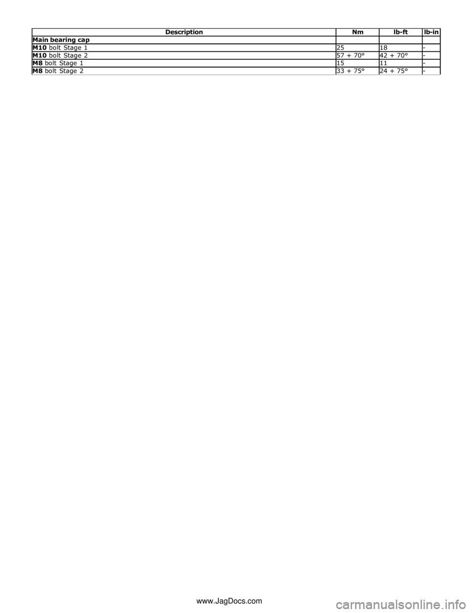
Main bearing cap M10 bolt Stage 1 25 18 - M10 bolt Stage 2 57 + 70° 42 + 70° - M8 bolt Stage 1 15 11 - M8 bolt Stage 2 33 + 75° 24 + 75° - www.JagDocs.com
Page 853 of 3039
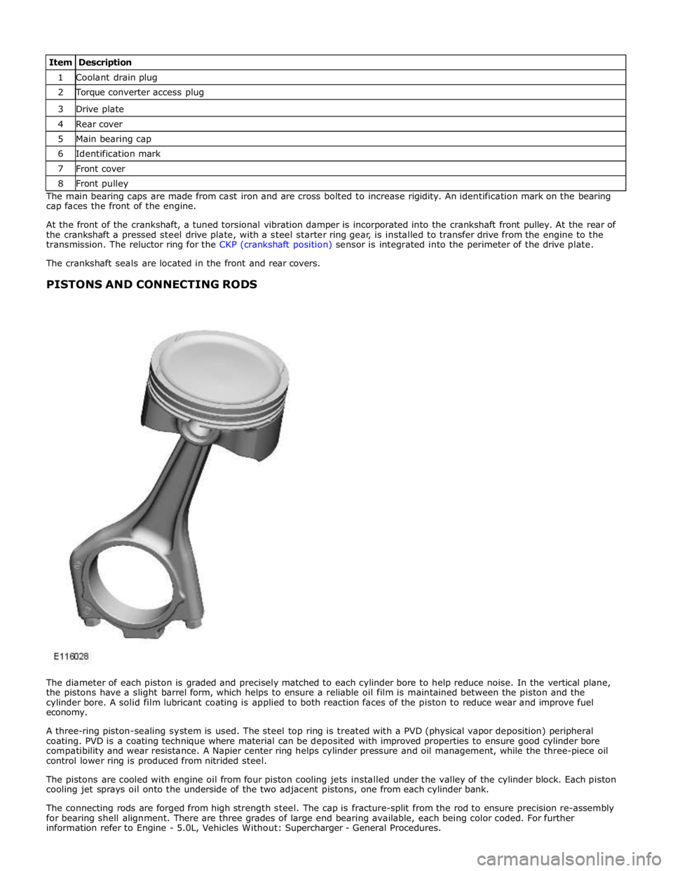
1 Coolant drain plug 2 Torque converter access plug 3 Drive plate 4 Rear cover 5 Main bearing cap 6 Identification mark 7 Front cover 8 Front pulley The main bearing caps are made from cast iron and are cross bolted to increase rigidity. An identification mark on the bearing
cap faces the front of the engine.
At the front of the crankshaft, a tuned torsional vibration damper is incorporated into the crankshaft front pulley. At the rear of
the crankshaft a pressed steel drive plate, with a steel starter ring gear, is installed to transfer drive from the engine to the
transmission. The reluctor ring for the CKP (crankshaft position) sensor is integrated into the perimeter of the drive plate.
The crankshaft seals are located in the front and rear covers.
PISTONS AND CONNECTING RODS
The diameter of each piston is graded and precisely matched to each cylinder bore to help reduce noise. In the vertical plane,
the pistons have a slight barrel form, which helps to ensure a reliable oil film is maintained between the piston and the
cylinder bore. A solid film lubricant coating is applied to both reaction faces of the piston to reduce wear and improve fuel
economy.
A three-ring piston-sealing system is used. The steel top ring is treated with a PVD (physical vapor deposition) peripheral
coating. PVD is a coating technique where material can be deposited with improved properties to ensure good cylinder bore
compatibility and wear resistance. A Napier center ring helps cylinder pressure and oil management, while the three-piece oil
control lower ring is produced from nitrided steel.
The pistons are cooled with engine oil from four piston cooling jets installed under the valley of the cylinder block. Each piston
cooling jet sprays oil onto the underside of the two adjacent pistons, one from each cylinder bank.
The connecting rods are forged from high strength steel. The cap is fracture-split from the rod to ensure precision re-assembly
for bearing shell alignment. There are three grades of large end bearing available, each being color coded. For further
information refer to Engine - 5.0L, Vehicles Without: Supercharger - General Procedures.
Page 857 of 3039
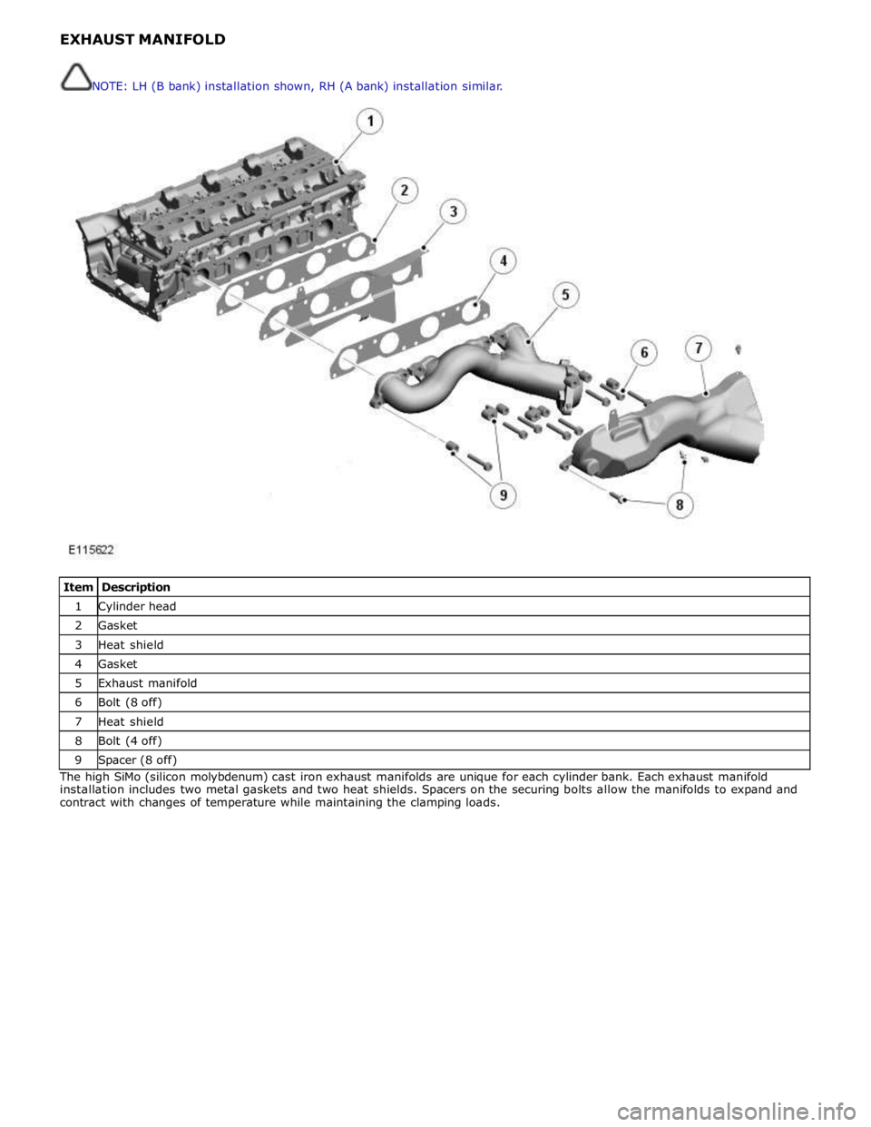
1 Cylinder head 2 Gasket 3 Heat shield 4 Gasket 5 Exhaust manifold 6 Bolt (8 off) 7 Heat shield 8 Bolt (4 off) 9 Spacer (8 off) The high SiMo (silicon molybdenum) cast iron exhaust manifolds are unique for each cylinder bank. Each exhaust manifold
installation includes two metal gaskets and two heat shields. Spacers on the securing bolts allow the manifolds to expand and
contract with changes of temperature while maintaining the clamping loads. NOTE: LH (B bank) installation shown, RH (A bank) installation similar.
Page 860 of 3039

1 Bolt (3 off) 2 VCT unit 3 Filter 4 Camshaft 5 Inner plate 6 Housing and sprocket 7 Rotor assembly 8 Reed plate 9 Spring and lock pin 10 Spring (3 off) 11 Tip seal (3 off) 12 Spring (2 off) 13 Tip seal (2 off) 14 Spring The VCT units change the position of the camshafts in relation to the timing chains.
Page 861 of 3039
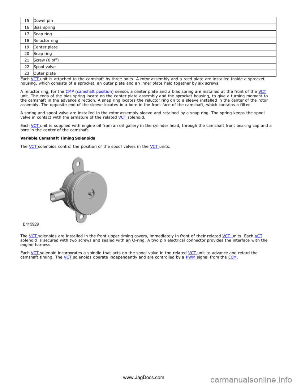
16 Bias spring 17 Snap ring 18 Reluctor ring 19 Center plate 20 Snap ring 21 Screw (6 off) 22 Spool valve 23 Outer plate Each VCT unit is attached to the camshaft by three bolts. A rotor assembly and a reed plate are installed inside a sprocket housing, which consists of a sprocket, an outer plate and an inner plate held together by six screws.
A reluctor ring, for the CMP (camshaft position) sensor, a center plate and a bias spring are installed at the front of the VCT unit. The ends of the bias spring locate on the center plate assembly and the sprocket housing, to give a turning moment to
the camshaft in the advance direction. A snap ring locates the reluctor ring on to a sleeve installed in the center of the rotor
assembly. The opposite end of the sleeve locates in a bore in the front face of the camshaft, which contains a filter.
A spring and spool valve are installed in the rotor assembly sleeve and retained by a snap ring. The spring keeps the spool
valve in contact with the armature of the related VCT solenoid.
Each VCT unit is supplied with engine oil from an oil gallery in the cylinder head, through the camshaft front bearing cap and a bore in the center of the camshaft.
Variable Camshaft Timing Solenoids
The VCT solenoids control the position of the spool valves in the VCT units.
The VCT solenoids are installed in the front upper timing covers, immediately in front of their related VCT units. Each VCT solenoid is secured with two screws and sealed with an O-ring. A two pin electrical connector provides the interface with the
engine harness.
Each VCT solenoid incorporates a spindle that acts on the spool valve in the related VCT unit to advance and retard the camshaft timing. The VCT solenoids operate independently and are controlled by a PWM signal from the ECM. www.JagDocs.com
Page 903 of 3039
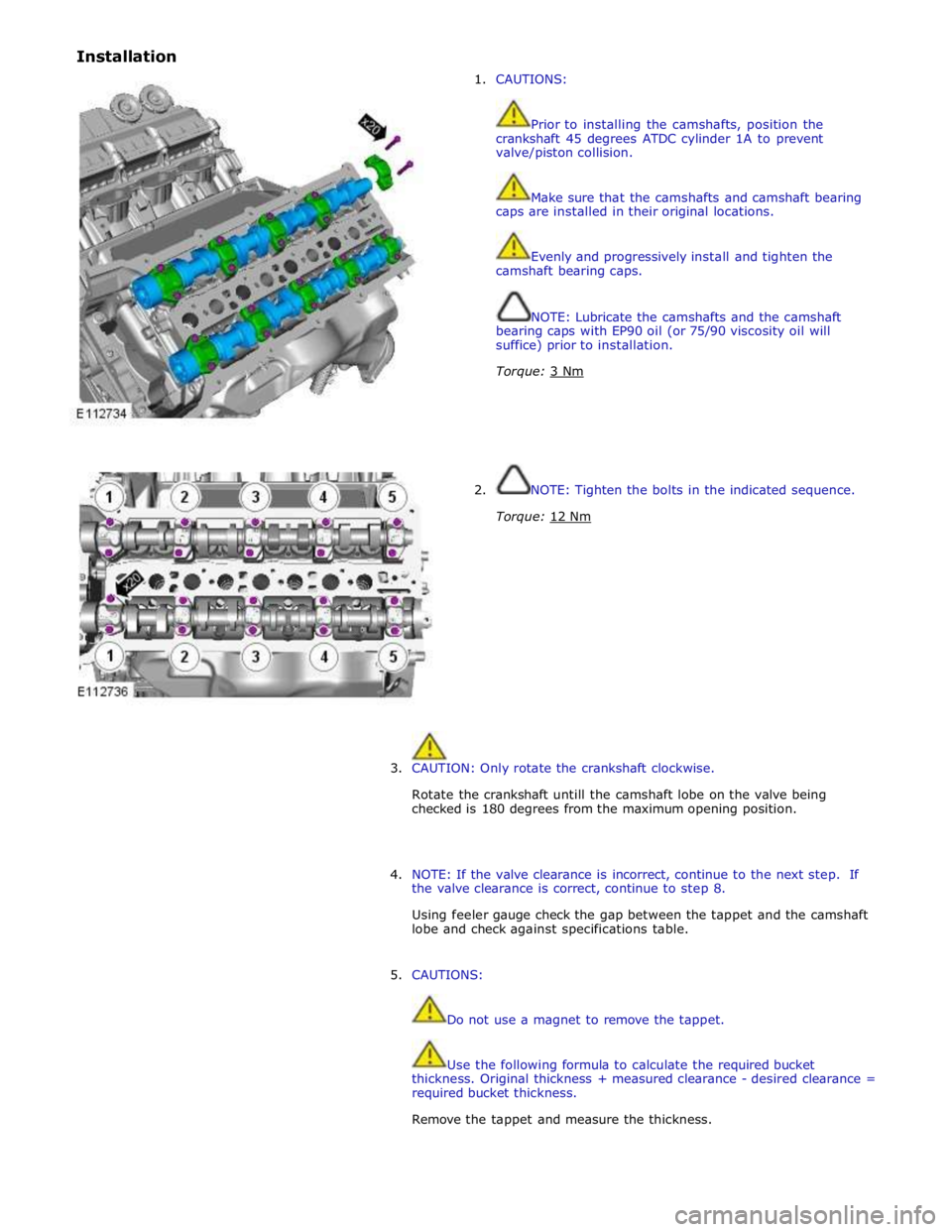
Installation
1. CAUTIONS:
Prior to installing the camshafts, position the
crankshaft 45 degrees ATDC cylinder 1A to prevent
valve/piston collision.
Make sure that the camshafts and camshaft bearing
caps are installed in their original locations.
Evenly and progressively install and tighten the
camshaft bearing caps.
NOTE: Lubricate the camshafts and the camshaft
bearing caps with EP90 oil (or 75/90 viscosity oil will
suffice) prior to installation.
Torque: 3 Nm
2. NOTE: Tighten the bolts in the indicated sequence.
Torque: 12 Nm
3. CAUTION: Only rotate the crankshaft clockwise.
Rotate the crankshaft untill the camshaft lobe on the valve being
checked is 180 degrees from the maximum opening position.
4. NOTE: If the valve clearance is incorrect, continue to the next step. If
the valve clearance is correct, continue to step 8.
Using feeler gauge check the gap between the tappet and the camshaft
lobe and check against specifications table.
5. CAUTIONS:
Do not use a magnet to remove the tappet.
Use the following formula to calculate the required bucket
thickness. Original thickness + measured clearance - desired clearance =
required bucket thickness.
Remove the tappet and measure the thickness.
Page 906 of 3039
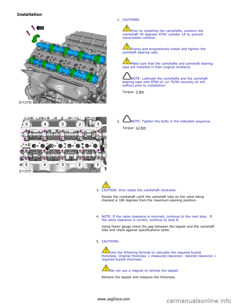
Installation
1. CAUTIONS:
Prior to installing the camshafts, position the
crankshaft 45 degrees ATDC cylinder 1A to prevent
valve/piston collision.
Evenly and progressively install and tighten the
camshaft bearing caps.
Make sure that the camshafts and camshaft bearing
caps are installed in their original locations.
NOTE: Lubricate the camshafts and the camshaft
bearing caps with EP90 oil (or 75/90 viscosity oil will
suffice) prior to installation.
Torque: 3 Nm
2. NOTE: Tighten the bolts in the indicated sequence.
Torque: 12 Nm
3. CAUTION: Only rotate the crankshaft clockwise.
Rotate the crankshaft untill the camshaft lobe on the valve being
checked is 180 degrees from the maximum opening position.
4. NOTE: If the valve clearance is incorrect, continue to the next step. If
the valve clearance is correct, continue to step 8.
Using feeler gauge check the gap between the tappet and the camshaft
lobe and check against specifications table.
5. CAUTIONS:
Use the following formula to calculate the required bucket
thickness. Original thickness + measured clearance - desired clearance =
required bucket thickness.
Do not use a magnet to remove the tappet.
Remove the tappet and measure the thickness. www.JagDocs.com
Page 910 of 3039
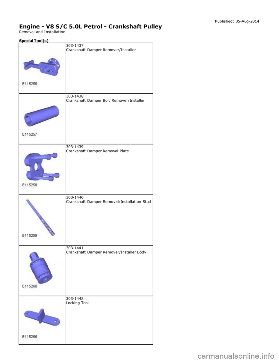
303-1438
Crankshaft Damper Bolt Remover/Installer
303-1439
Crankshaft Damper Removal Plate
303-1440
Crankshaft Damper Removal/Installation Stud
303-1441
Crankshaft Damper Remover/Installer Body
303-1448
Locking Tool
Page 915 of 3039
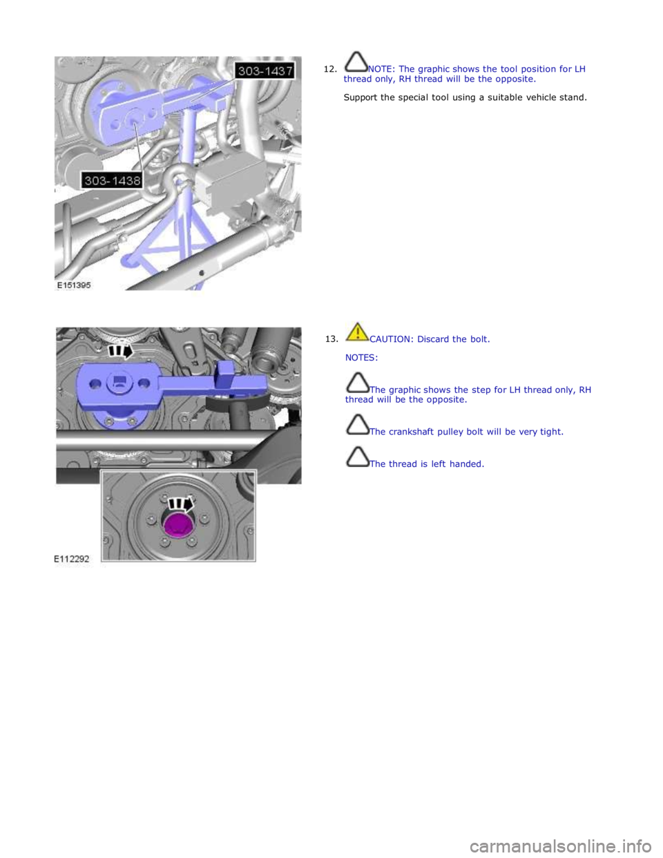
12.
13. NOTE: The graphic shows the tool position for LH
thread only, RH thread will be the opposite.
Support the special tool using a suitable vehicle stand.
CAUTION: Discard the bolt.
NOTES:
The graphic shows the step for LH thread only, RH
thread will be the opposite.
The crankshaft pulley bolt will be very tight.
The thread is left handed.
Page 916 of 3039
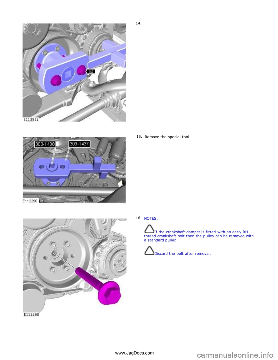
14.
15.
16.
Remove the special tool.
NOTES:
If the crankshaft damper is fitted with an early RH
thread crankshaft bolt then the pulley can be removed with
a standard puller.
Discard the bolt after removal. www.JagDocs.com