Bolt JAGUAR XFR 2010 1.G Manual PDF
[x] Cancel search | Manufacturer: JAGUAR, Model Year: 2010, Model line: XFR, Model: JAGUAR XFR 2010 1.GPages: 3039, PDF Size: 58.49 MB
Page 775 of 3039

Steering wheel retaining bolt 60 44 - Steering column pinch bolt 35 26 - Steering column retaining nuts 30* 22 - Tilt solenoid retaining bolts 1 - 9 Telescopic solenoid retaining bolts 1 - 9 Telescopic housing retaining bolts 8 - 71 If you are re-using this fixing on a vehicle built prior to VIN N83337, then tighten to 25 Nm. If you are replacing a fixing, then
you must tighten to 30 Nm.
Page 780 of 3039
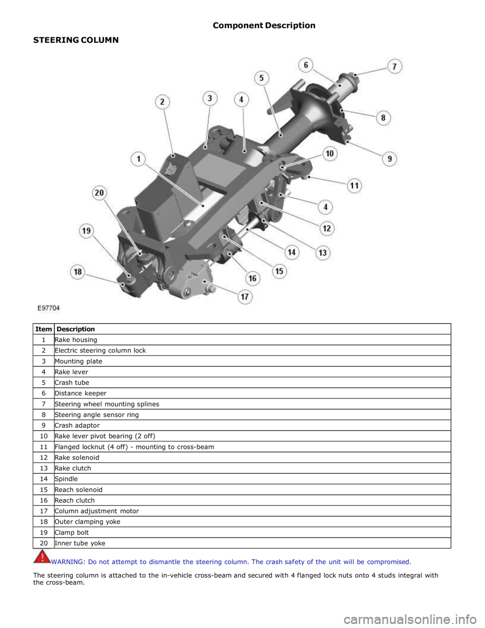
STEERING COLUMN Component Description
Item Description 1 Rake housing 2 Electric steering column lock 3 Mounting plate 4 Rake lever 5 Crash tube 6 Distance keeper 7 Steering wheel mounting splines 8 Steering angle sensor ring 9 Crash adaptor 10 Rake lever pivot bearing (2 off) 11 Flanged locknut (4 off) - mounting to cross-beam 12 Rake solenoid 13 Rake clutch 14 Spindle 15 Reach solenoid 16 Reach clutch 17 Column adjustment motor 18 Outer clamping yoke 19 Clamp bolt 20 Inner tube yoke
WARNING: Do not attempt to dismantle the steering column. The crash safety of the unit will be compromised.
The steering column is attached to the in-vehicle cross-beam and secured with 4 flanged lock nuts onto 4 studs integral with
the cross-beam.
Page 782 of 3039
16 Ball (12 off) 17 Distance keeper 18 Crash tube The column comprises a cast magnesium mounting bracket which provides the attachment to the cross-beam. Attached to the
mounting bracket is a rake lever which is attached to the mounting bracket at the lower end with two pivot bearings. The
bearings allow the rake lever to rotate upwards or downward to adjust the column rake.
The rake lever also provides for the attachment of the rake housing which can slide within the lever to provide the reach
adjustment. Within the rake housing is the axial housing which is supported on each side with 6 ball bearings which allow the
rake housing to move forward or backwards. The bearings on each side are arranged in groups of 3 bearings and are separated
by a distance keeper which allows the housing to supported on bearings along its length. Within the axial housing is a tube
which is supported at the upper end of the column on the upper bearing. The tube has a central splined hole which provides for
the fitment of the splined shaft. The splined shaft can slide within the tube on the splines when the column reach is adjusted
or the column collapses in a crash condition. The splined shaft also passes rotary motion from the steering wheel through the
length of the column to the outer clamping yoke which is supported on the lower bearing.
The electric steering column lock is attached to the top of the rake lever. A lock bolt within the steering column lock engages in
one of 8 slots in the locking sleeve located at the lower end of the column preventing rotation of the steering wheel. The
locking sleeve is retained by a tolerance ring which in turn is located on the outer diameter of the tube yoke. The tolerance
ring allows a specified amount of torque to be applied to the splined shaft before it slips, preventing damage to the column
lock due to excessive force being applied to the steering wheel when the lock is engaged. The tolerance ring is designed to
slip on the splined shaft when the applied torque exceeds the fitted slip load of 200 Nm minimum. Repeated rotation of the
lock collar will reduce its slipping torque to 100 Nm minimum. The lock is controlled by the CJB.
A steering angle sensor is located at the upper end of the steering column and is attached to the crash adaptor. The sensor
measures steering rotation via a toothed wheel located on the splined tube at the upper end of the column. The sensor
receives a power supply from the CJB and supplies 2 signals (A and B) relating to the steering rotation to the ABS (anti-lock brake system) module. The module transmits this data on the high speed CAN bus for use by other vehicle systems. Refer to: Anti-Lock Control - Stability Assist (206-09 Anti-Lock Control - Stability Assist, Description and Operation).
The steering column is adjustable electrically, for reach and rake. The adjustment mechanism comprises an electric adjustment
motor, a lead screw, a rake solenoid, a reach solenoid, a reach clutch and a rake clutch. The column adjustment is controlled
manually using a joystick switch located on the LH (left-hand) side of the column lower cowl. The joystick can be moved
forward and backward to adjust the column reach in and out and moved up and down to adjust the rake. The switch selection
energizes the adjustment motor in the applicable direction and also engages the applicable solenoid and clutch.
When the joystick switch is rotated to the 'auto' position, the steering column will adjust to the uppermost rake position when
the ignition is switched off. It will re-adjust to the position corresponding to the memory position for the remote handset when
the ignition is switched on.
The memory function of the electric column is linked to and controlled by the driver's seat module. The module provides for the
storage of three separate memory positions which are stored against 3 individual remote handsets.
Refer to: Seats (501-10 Seating, Description and Operation).
The steering wheel locates on a splined shaft in the upper column assembly and is secured with a bolt. The steering wheel
houses the driver's airbag and switches for the audio system, gear change and speed control. A clockspring is used to connect
the steering wheel electrical components to the vehicle harness.
Two plastic shrouds are fitted to the upper column assembly. The lower shroud is fitted with an energy absorbing foam pad to
minimize leg injury in the event of an accident.
www.JagDocs.com
Page 783 of 3039
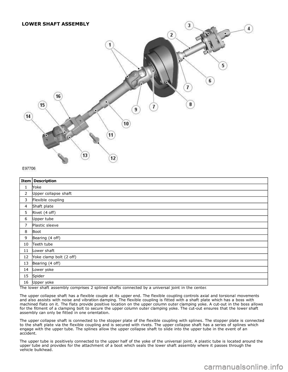
1 Yoke 2 Upper collapse shaft 3 Flexible coupling 4 Shaft plate 5 Rivet (4 off) 6 Upper tube 7 Plastic sleeve 8 Boot 9 Bearing (4 off) 10 Teeth tube 11 Lower shaft 12 Yoke clamp bolt (2 off) 13 Bearing (4 off) 14 Lower yoke 15 Spider 16 Upper yoke The lower shaft assembly comprises 2 splined shafts connected by a universal joint in the center.
The upper collapse shaft has a flexible couple at its upper end. The flexible coupling controls axial and torsional movements
and also assists with noise and vibration damping. The flexible coupling is fitted with a shaft plate which has a boss with
machined flats on it. The flats provide positive location on the upper column outer clamping yoke. A cut-out in the boss allows
for the fitment of a clamping bolt to secure the upper column outer clamping yoke. The cut-out ensures that the lower shaft
assembly can only be fitted in one orientation.
The upper collapse shaft is connected to the stopper plate of the flexible coupling with splines. The stopper plate is connected
to the shaft plate via the flexible coupling and is secured with rivets. The upper collapse shaft has a series of splines which
engage with the upper tube. The splines allow the upper collapse shaft to slide into the upper tube in the event of an
accident.
The upper tube is positively connected to the upper half of the yoke of the universal joint. A plastic tube is located around the
upper tube and provides for the attachment of a boot which seals the lower shaft assembly where it passes through the
vehicle bulkhead. LOWER SHAFT ASSEMBLY
Page 787 of 3039
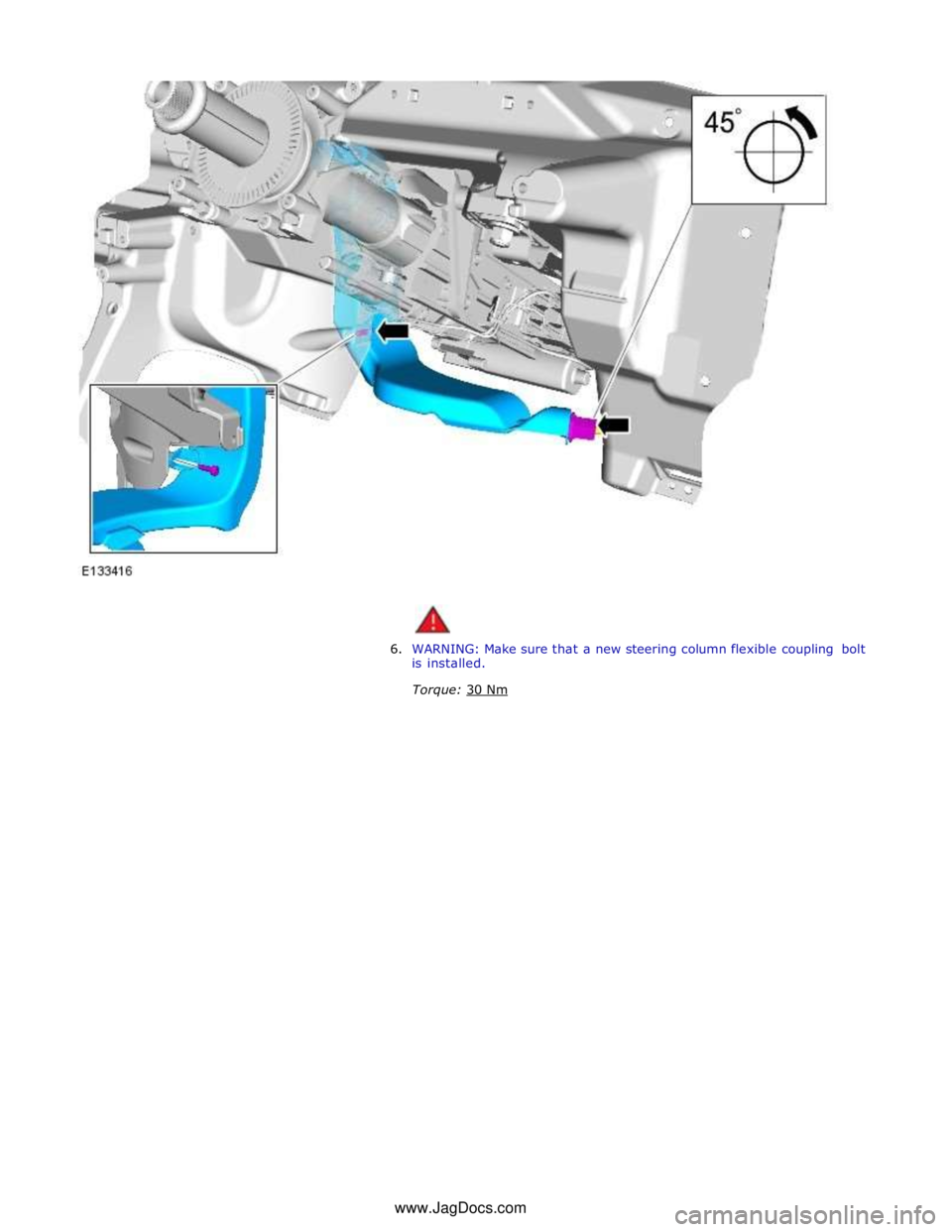
6. WARNING: Make sure that a new steering column flexible coupling bolt
is installed.
Torque: 30 Nm www.JagDocs.com
Page 790 of 3039
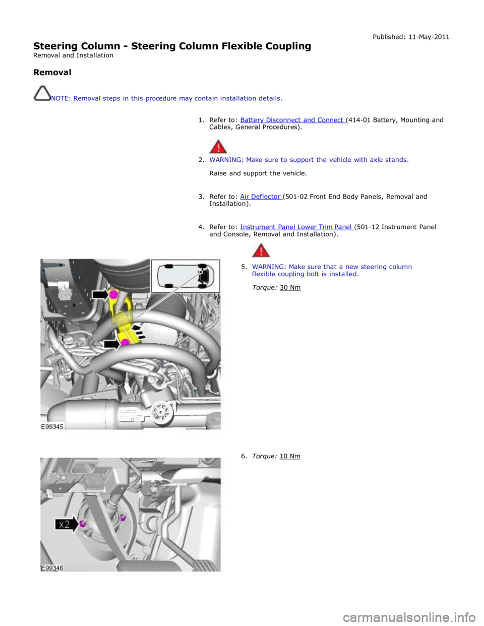
Steering Column - Steering Column Flexible Coupling
Removal and Installation
Removal
NOTE: Removal steps in this procedure may contain installation details. Published: 11-May-2011
1. Refer to: Battery Disconnect and Connect (414-01 Battery, Mounting and Cables, General Procedures).
2. WARNING: Make sure to support the vehicle with axle stands.
Raise and support the vehicle.
3. Refer to: Air Deflector (501-02 Front End Body Panels, Removal and Installation).
4. Refer to: Instrument Panel Lower Trim Panel (501-12 Instrument Panel and Console, Removal and Installation).
5. WARNING: Make sure that a new steering column
flexible coupling bolt is installed.
Torque: 30 Nm
6. Torque: 10 Nm
Page 792 of 3039
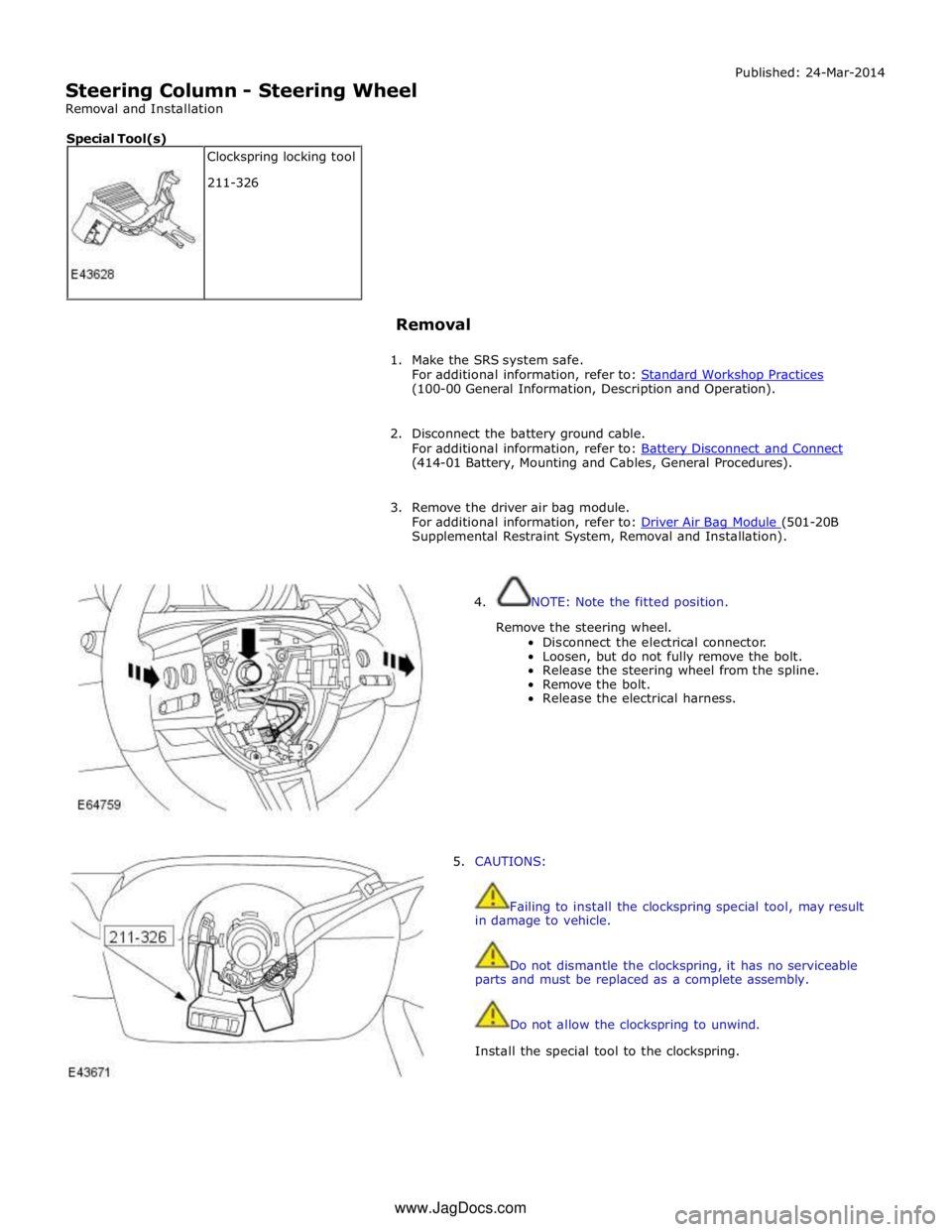
Steering Column - Steering Wheel
Removal and Installation Published: 24-Mar-2014
Removal
1. Make the SRS system safe.
For additional information, refer to: Standard Workshop Practices (100-00 General Information, Description and Operation).
2. Disconnect the battery ground cable.
For additional information, refer to: Battery Disconnect and Connect (414-01 Battery, Mounting and Cables, General Procedures).
3. Remove the driver air bag module.
For additional information, refer to: Driver Air Bag Module (501-20B Supplemental Restraint System, Removal and Installation).
4. NOTE: Note the fitted position.
Remove the steering wheel.
Disconnect the electrical connector.
Loosen, but do not fully remove the bolt.
Release the steering wheel from the spline.
Remove the bolt.
Release the electrical harness.
5. CAUTIONS:
Failing to install the clockspring special tool, may result
in damage to vehicle.
Do not dismantle the clockspring, it has no serviceable
parts and must be replaced as a complete assembly.
Do not allow the clockspring to unwind.
Install the special tool to the clockspring. Clockspring locking tool
211-326 Special Tool(s) www.JagDocs.com
Page 793 of 3039
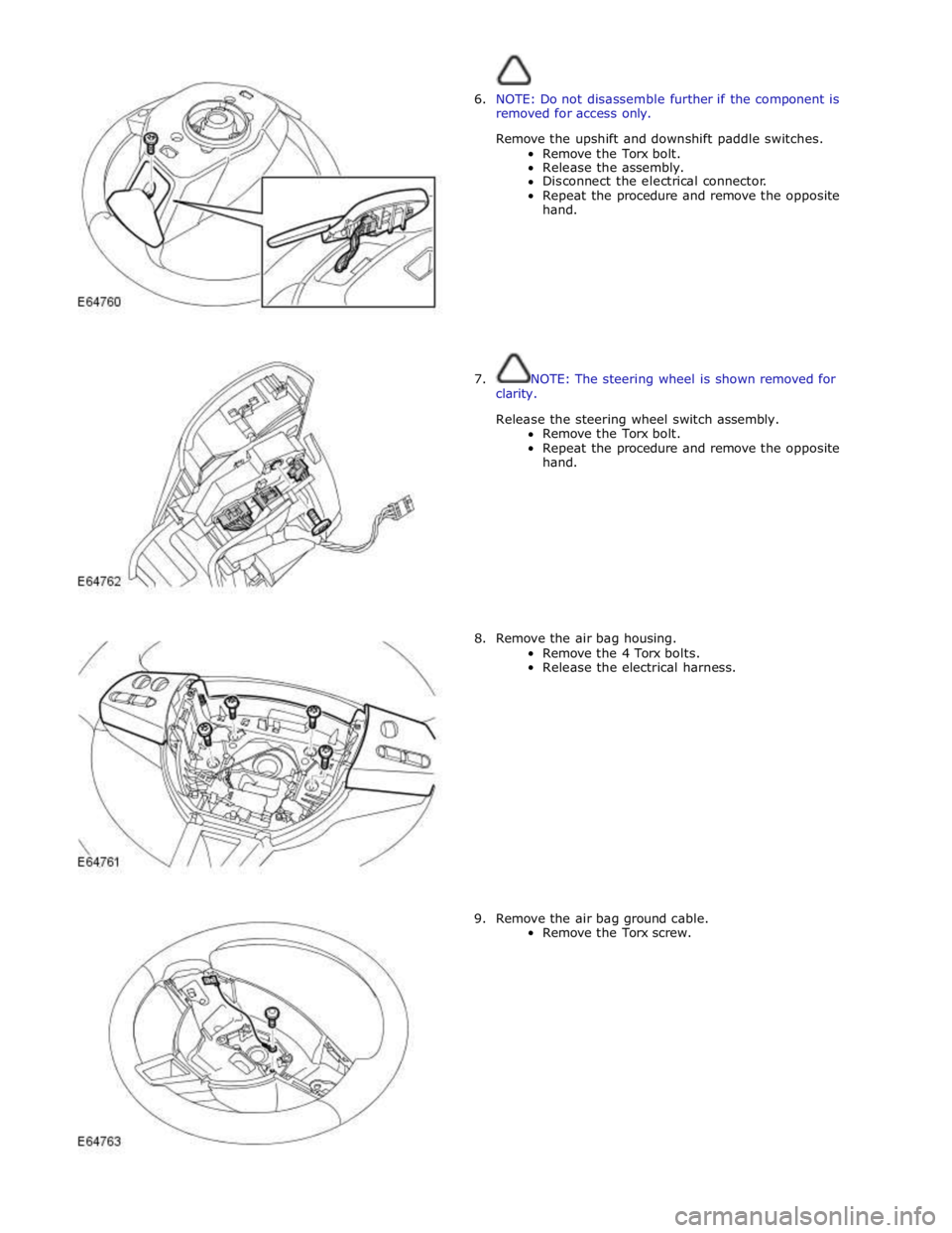
6. NOTE: Do not disassemble further if the component is
removed for access only.
Remove the upshift and downshift paddle switches.
Remove the Torx bolt.
Release the assembly.
Disconnect the electrical connector.
Repeat the procedure and remove the opposite
hand.
7. NOTE: The steering wheel is shown removed for
clarity.
Release the steering wheel switch assembly.
Remove the Torx bolt.
Repeat the procedure and remove the opposite
hand.
8. Remove the air bag housing.
Remove the 4 Torx bolts.
Release the electrical harness.
9. Remove the air bag ground cable.
Remove the Torx screw.
Page 813 of 3039
Component Tests
Engine Oil Leaks
NOTE: Before installing new gaskets or oil seals, make sure that the fault is clearly established.
If the oil leak cannot be identified clearly by a visual inspection, carry out an Ultraviolet test:
Fluorescent Oil Additive Method
1. Clean the engine with a suitable cleaning fluid (brake cleaner).
2. Drain the engine oil and refill with recommended oil, premixed with Diesel Engine Oil Dye or equivalent. Use a minimum
14.8 ml (0.5 ounce) to a maximum 29.6 ml (1 ounce) of fluorescent additive to all engines. If oil is not premixed,
fluorescent additive must first be added to the crankcase.
3. Run engine for 15 minutes. Stop the engine and inspect all seal and gasket areas for leaks using a 12 Volt Master UV
Diagnostic Inspection Kit or equivalent. A clear bright yellow or orange area will identify leak. For extremely small
leaks, several hours may be required for the leak to appear.
4. As necessary, pressurize the main oil gallery system to locate leaks due to incorrectly sealed, loose or cocked plugs. If
the flywheel bolts leak oil, look for sealer on the threads.
5. Repair all leaks as necessary.
Compression Test General Remarks
NOTES:
Removing fuses and disconnecting electrical components may cause the Engine Control Module (ECM) to log Diagnostic
Trouble Codes (DTCs). After the measurements have been carried out, DTCs should be cleared from memory by connecting to
the Manufacturer Approved Diagnostic System.
Only check the compression pressure with the valves set to the prescribed clearance (if this can be adjusted).
The compression pressure should be checked with the engine at normal operating temperature.
Check the Compression Pressure
WARNING: Move gear selector lever to 'P' position. Failure to follow this instruction may result in personal injury.
1. Remove the fuel pump relay.
2. Start the engine - the engine will start, run for a few seconds then stall.
3. Remove the spark plugs.
4. Install the compression tester.
5. Install an auxiliary starter switch in the starting circuit. With the ignition switch OFF, using the auxiliary starter switch,
crank the engine a minimum of five compression strokes and record the highest reading. Note the approximate number
of compression strokes required to obtain the highest reading.
6. Repeat the test on each cylinder, cranking the engine approximately the same number of compression strokes.
7. Install the removed components in reverse order, observing the specified tightening torques.
8. Clear all DTCs from the ECM.
Interpretation of the Results
NOTE: Due to the possibility of loose carbon that has become trapped between the valve face and seat effecting the
pressure readings, when carrying out a compression test and cylinders are found to have low pressures, install the spark plugs,
road test the vehicle and re-test the suspect cylinders. If the correct pressures are restored, no further action is required.
The indicated compression pressures are considered within specification if the lowest reading cylinder is within 75% of the
highest reading.
If the cylinder pressures are found to be low, carry out a leakdown test to determine the location of the fault (if any leakback
can be heard through the engine breather system suspect the piston rings, if any leakback can be heard through the inlet
system suspect the inlet valve or seat, if any leakback can be heard through the exhaust manifold suspect the exhaust valve
or seat. If the measurements for two cylinders next to each other are both too low then it is very likely that the cylinder head
gasket between them is burnt through. This can also be recognized by traces of engine oil in the coolant and/or coolant in the
Page 845 of 3039
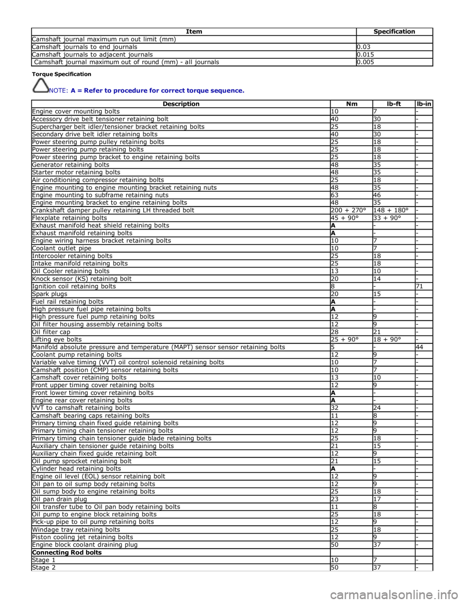
Item Specification Camshaft journal maximum run out limit (mm) Camshaft journals to end journals 0.03 Camshaft journals to adjacent journals 0.015 Camshaft journal maximum out of round (mm) - all journals 0.005 Torque Specification
NOTE: A = Refer to procedure for correct torque sequence.
Description Nm lb-ft lb-in Engine cover mounting bolts 10 7 - Accessory drive belt tensioner retaining bolt 40 30 - Supercharger belt idler/tensioner bracket retaining bolts 25 18 - Secondary drive belt idler retaining bolts 40 30 - Power steering pump pulley retaining bolts 25 18 - Power steering pump retaining bolts 25 18 - Power steering pump bracket to engine retaining bolts 25 18 - Generator retaining bolts 48 35 - Starter motor retaining bolts 48 35 - Air conditioning compressor retaining bolts 25 18 - Engine mounting to engine mounting bracket retaining nuts 48 35 - Engine mounting to subframe retaining nuts 63 46 - Engine mounting bracket to engine retaining bolts 48 35 - Crankshaft damper pulley retaining LH threaded bolt 200 + 270° 148 + 180° - Flexplate retaining bolts 45 + 90° 33 + 90° - Exhaust manifold heat shield retaining bolts A - - Exhaust manifold retaining bolts A - - Engine wiring harness bracket retaining bolts 10 7 - Coolant outlet pipe 10 7 - Intercooler retaining bolts 25 18 - Intake manifold retaining bolts 25 18 - Oil Cooler retaining bolts 13 10 - Knock sensor (KS) retaining bolt 20 14 - Ignition coil retaining bolts 8 - 71 Spark plugs 20 15 - Fuel rail retaining bolts A - - High pressure fuel pipe retaining bolts A - - High pressure fuel pump retaining bolts 12 9 - Oil filter housing assembly retaining bolts 12 9 - Oil filter cap 28 21 - Lifting eye bolts 25 + 90° 18 + 90° - Manifold absolute pressure and temperature (MAPT) sensor sensor retaining bolts 5 - 44 Coolant pump retaining bolts 12 9 - Variable valve timing (VVT) oil control solenoid retaining bolts 10 7 - Camshaft position (CMP) sensor retaining bolts 10 7 - Camshaft cover retaining bolts 13 10 - Front upper timing cover retaining bolts 12 9 - Front lower timing cover retaining bolts A - - Engine rear cover retaining bolts A - - VVT to camshaft retaining bolts 32 24 - Camshaft bearing caps retaining bolts 11 8 - Primary timing chain fixed guide retaining bolts 12 9 - Primary timing chain tensioner retaining bolts 12 9 - Primary timing chain tensioner guide blade retaining bolts 25 18 - Auxiliary chain tensioner guide retaining bolts 21 15 - Auxiliary chain fixed guide retaining bolt 12 9 - Oil pump sprocket retaining bolt 21 15 - Cylinder head retaining bolts A - - Engine oil level (EOL) sensor retaining bolt 12 9 - Oil pan to oil sump body retaining bolts 12 9 - Oil sump body to engine retaining bolts 25 18 - Oil pan drain plug 23 17 - Oil transfer tube to Oil pan body retaining bolts 11 8 - Oil pump to engine block retaining bolts 25 18 - Pick-up pipe to oil pump retaining bolts 12 9 - Windage tray retaining bolts 25 18 - Piston cooling jet retaining bolts 12 9 - Engine block coolant draining plug 50 37 - Connecting Rod bolts Stage 1 10 7 - Stage 2 50 37 -