JAGUAR XJ6 1994 2.G Workshop Manual
Manufacturer: JAGUAR, Model Year: 1994, Model line: XJ6, Model: JAGUAR XJ6 1994 2.GPages: 521, PDF Size: 17.35 MB
Page 281 of 521
Body Components & Trim
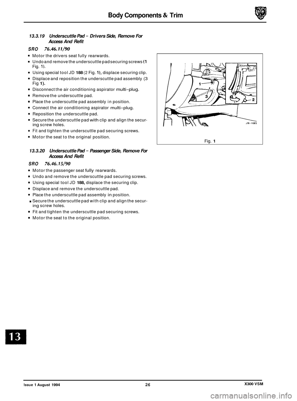
13.3.19 Underscuttle Pad - Drivers Side, Remove For
Access And Refit
SRO 76.46.11/90
Motor the drivers seat fully rearwards.
Undo and remove the underscuttle pad securing screws (1
Using special tool JD 188 (2 Fig. I), displace securing clip.
Displace and reposition the underscuttle pad assembly (3
Disconnect the air conditioning aspirator multi-plug.
Remove the underscuttle pad.
Place the underscuttle pad assembly in position.
Connect the air conditioning aspirator multi-plug.
Reposition the underscuttle pad.
Secure the underscuttle pad with clip and align the secur-
Fit and tighten the underscuttle pad securing screws.
Motor the seat to the original position.
Fig.
1).
Fig 1).
ing screw
holes.
13.3.20 Underscuttle Pad - Passenger Side, Remove For
Access And Refit
SRO 76.46.15/90
Motor the passenger seat fully rearwards.
Undo and remove the underscuttle pad securing screws.
Using special tool JD 188, displace the securing clip.
Displace and remove the underscuttle pad.
Place the underscuttle pad assembly in position.
. Secure the underscuttle pad with clip and align the secur-
Fit and tighten the underscuttle pad securing screws.
Motor the seat to the original position.
ing screw holes. Fig.
1
X300 VSM Issue 1 August 1994 26
Page 282 of 521
Body Components & Trim -
13.3.21 Fascia Closing Panel - Passenger Side, Renew
SRO 76.46.27
Remove for access the passenger side underscuttle pad,
see sub-section 13.3.20.
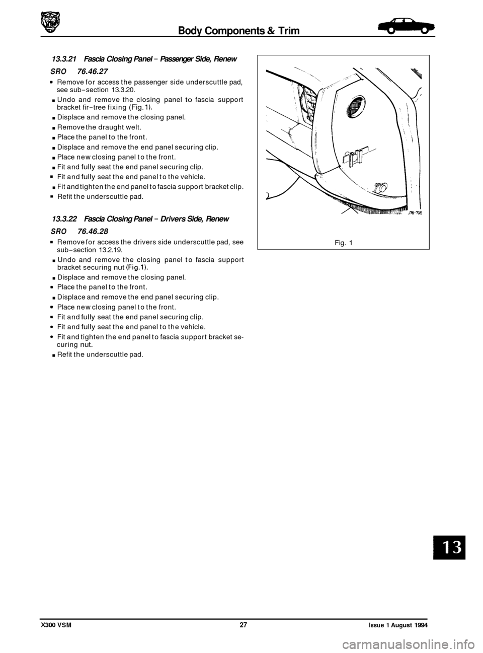
. Undo and remove the closing panel to fascia support
bracket fir-tree fixing (Fig. 1).
. Displace and remove the closing panel.
. Remove the draught welt.
. Place the panel to the front.
. Displace and remove the end panel securing clip.
. Place new closing panel to the front.
. Fit and fully seat the end panel securing clip.
Fit and fully seat the end panel to the vehicle.
. Fit and tighten the end panel to fascia support bracket clip.
Refit the underscuttle pad.
13.3.22 Fascia Closing Panel - Drivers Side, Renew
SRO 76.46.28
Remove for access the drivers side underscuttle pad, see
. Undo and remove the closing panel to fascia support
. Displace and remove the closing panel.
. Displace and remove the end panel securing clip.
= Fit and fully seat the end panel securing clip.
Fit and fully seat the end panel to the vehicle.
Fit and tighten the end panel to fascia support bracket se-
. Refit the underscuttle pad.
sub-section 13.2.19.
bracket securing
nut (Fig.1).
Place the panel to the front.
Place new closing panel to the front.
curing
nut.
Fig. 1
X300 VSM 27 Issue 1 August 1994
-
Page 283 of 521
Body Components & Trim -
13.3.23 fascia Cenfer Veneer Panel, Renew
SRO 76.47.06
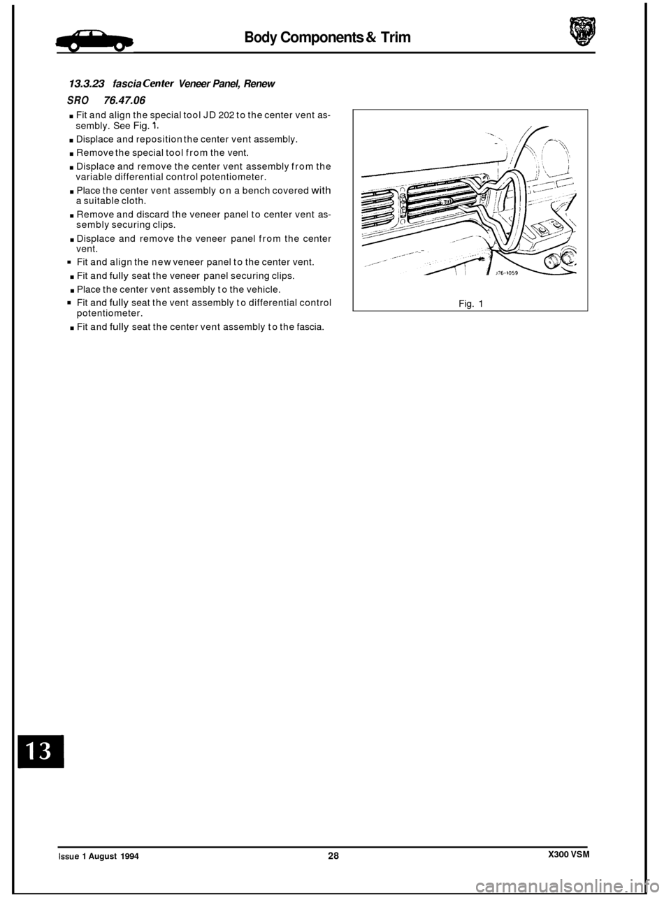
. Fit and align the special tool JD 202 to the center vent as-
. Displace and reposition the center vent assembly.
. Remove the special tool from the vent.
. Displace and remove the center vent assembly from the
. Place the center vent assembly on a bench covered with
. Remove and discard the veneer panel to center vent as-
. Displace and remove the veneer panel from the center
Fit and align the new veneer panel to the center vent.
. Fit and fully seat the veneer panel securing clips.
. Place the center vent assembly to the vehicle.
Fit and fully seat the vent assembly to differential control
. Fit and fully seat the center vent assembly to the fascia.
sembly.
See
Fig. 1.
variable differential control potentiometer.
a suitable cloth.
sembly securing clips.
vent.
potentiometer.
._-
Fig. 1
X300 VSM Issue 1 August 1994 28
Page 284 of 521

Body Components & Trim -
13.3.24 Console Finisher Veneer Panel, Renew
SRO 76.47.26
Apply the handbrake.
. Turn the ignition ON.
. Press the brake pedal and position the gear selector in 'N'.
Turn the ignition OFF.
. Remove the console ashtray, see sub-section 13.3.28.
9 Carefully displace the mode switch from the gear sur-
. Disconnect the mode switch from the harness multi-plug.
. Displace and remove the switch surround finisher.
. Displace and remove the gear lever surround finisher.
. Displace and remove the veneer panel rear finisher.
. Undo and remove the veneer panel wing nuts. See Fig. 2.
. Displace and remove the console finisher veneer panel.
. Remove the stud plates.
. Place the veneer panel aside.
. Place the new panel to the front.
Fit and align the stud plates.
. Fit and fully seat the veneer panel to the console.
. Fully seat the rear of the veneer panel.
. Fit and tighten the wing nuts.
. Fit and align the veneer panel rear finisher.
. Fit and fully seat the gear lever surround.
. Fit and fully seat the mode switch surround.
. Connect the mode switch to harness multi-plug.
. Fully seat the mode switch.
. Refit the ashtray.
. Place the gear selector in 'I".
round finisher. See Fig. 1.
See Fig. 1.
See Fig. 3.
Fig. 1
J76.801
Fig. 2
Fig. 3
X300 VSM 29 Issue 1 August 1994
Page 285 of 521
Body Components & Trim
13.3.25 Console Ashtray Lid Veneer Panel, Renew
SRO 76.47.27
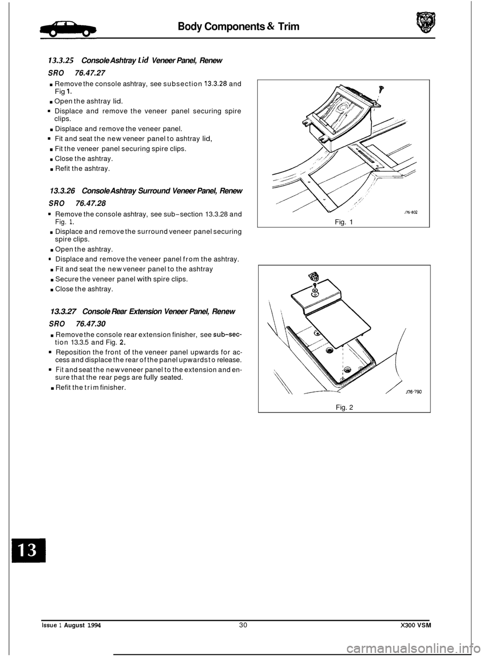
. Remove the console ashtray, see subsection 13.3.28 and
. Open the ashtray lid.
Fig 1.
Displace and remove the veneer panel securing spire
clips.
. Displace and remove the veneer panel.
Fit and seat the new veneer panel to ashtray lid,
. Fit the veneer panel securing spire clips.
. Close the ashtray.
. Refit the ashtray.
13.3.26 Console Ashtray Surround Veneer Panel, Renew
SRO 76.47.28
Remove the console ashtray, see sub-section 13.3.28 and Fig. 1.
. Displace and remove the surround veneer panel securing
spire clips.
. Open the ashtray.
9 Displace and remove the veneer panel from the ashtray.
. Fit and seat the new veneer panel to the ashtray
. Secure the veneer panel with spire clips.
. Close the ashtray.
13.3.27 Console Rear Extension Veneer Panel, Renew
SRO 76.47.30
. Remove the console rear extension finisher, see sub-sec- tion 13.3.5 and Fig. 2.
Reposition the front of the veneer panel upwards for ac- cess and displace the rear of the panel upwards to release.
Fit and seat the new veneer panel to the extension and en- sure that the rear pegs are fully seated.
. Refit the trim finisher. Fig.
1
Fig. 2
issue 1 August 1994 30 X300 VSM
0
0
0
0
Page 286 of 521
Body Components & Trim .B+La.
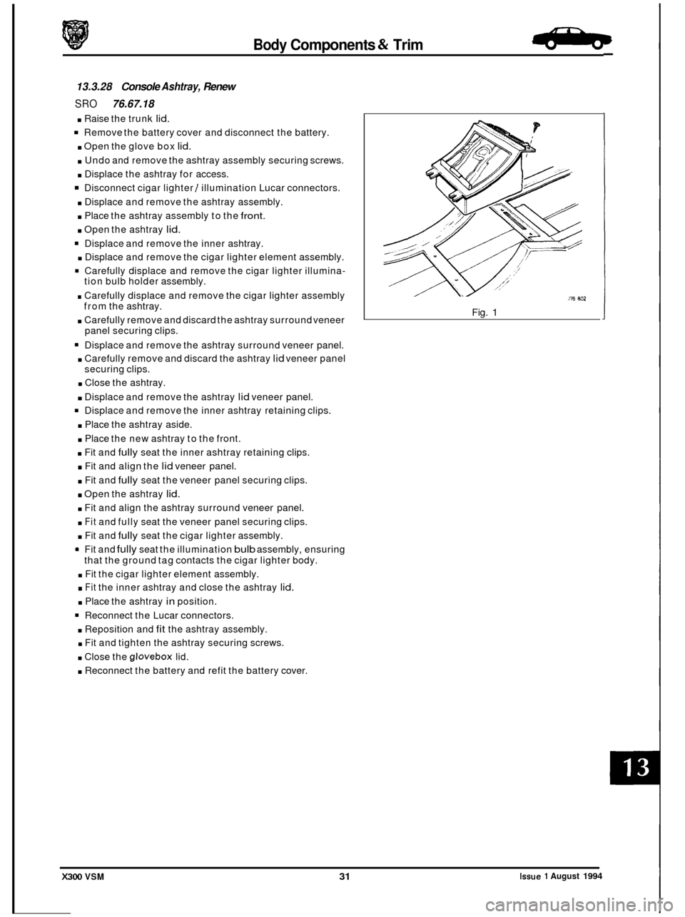
13.3.28 Console Ashtray, Renew
SRO 76.67.18
. Raise the trunk lid.
Remove the battery cover and disconnect the battery.
. Open the glove box lid.
. Undo and remove the ashtray assembly securing screws.
. Displace the ashtray for access.
Disconnect cigar lighter / illumination Lucar connectors.
. Displace and remove the ashtray assembly.
. Place the ashtray assembly to the front.
. Open the ashtray lid.
Displace and remove the inner ashtray.
. Displace and remove the cigar lighter element assembly.
Carefully displace and remove the cigar lighter illumina-
. Carefully displace and remove the cigar lighter assembly
. Carefully remove and discard the ashtray surround veneer
Displace and remove the ashtray surround veneer panel.
. Carefully remove and discard the ashtray lid veneer panel
securing clips.
. Close the ashtray.
. Displace and remove the ashtray lid veneer panel.
Displace and remove the inner ashtray retaining clips.
. Place the ashtray aside.
. Place the new ashtray to the front.
. Fit and fully seat the inner ashtray retaining clips.
. Fit and align the lid veneer panel.
. Fit and fully seat the veneer panel securing clips.
. Open the ashtray lid.
. Fit and align the ashtray surround veneer panel.
. Fit and fully seat the veneer panel securing clips.
. Fit and fully seat the cigar lighter assembly.
9 Fit and fully seat the illumination bulb assembly, ensuring
. Fit the cigar lighter element assembly.
. Fit the inner ashtray and close the ashtray lid.
. Place the ashtray in position.
Reconnect the Lucar connectors.
. Reposition and fit the ashtray assembly.
. Fit and tighten the ashtray securing screws.
. Close the glovebox lid.
. Reconnect the battery and refit the battery cover.
tion
bulb holder assembly.
from the ashtray.
panel securing clips.
that the ground tag contacts the cigar lighter body.
116 802
Fig. 1
Issue 1 August 1994 X300 VSM 31
Page 287 of 521

Body Components & Trim -
13.3.29 Steering Column Upper Cowl, Renew
SRO 76.46.02
Motor the drivers seat fully rearward.
Undo and remove the lower cowl fixing screws (1 Fig. 1).
. Displace and reposition the lower cowl (2 Fig. 1); discard
the ignition lock rubber gaiter
(3 Fig. 1).
. Motor the steering column fully upwards.
Undo and remove the upper column securing screws.
Motor the column fully downwards.
Displace and remove the upper cowl (4 Fig. 1).
Fit and align the new cowl into position.
. Motor the column fully upwards.
. Fit and tighten the cowl securing screws.
9 Fit a new ignition lock rubber gaiter and position the lower
. Fit and tighten the cowl securing screws.
. Motor the column to the original position.
cowl to
the steering column.
13.3.30 Steering Column Lower Cowl, Renew
SRO 76.46.03
= Motor the drivers seat fully rearwards.
. Undo and remove the lower column cowl securing screws
. Displace and reposition the lower cowl (2 Fig. 1).
. Disconnect the rheostat multi-plug (5 Fig. 1).
. Disconnect the tilt column harness multi-plug from the tilt
= Remove the cowl and place to the front; remove the igni-
Displace and remove the rheostat adjusting knob (7 Fig. 1).
. Undo and remove the rheostat securing screws (8 Fig. 1).
. Displace the tilt column switch retaining tangs and re-
move the switch.
. Place the cowl aside.
. Place the new lower cowl to the front.
. Fit and fully seat the column switch.
. Fit and align the rheostat. Fit and tighten the rheostat se-
. Fit and fully seat the rheostat knob.
Fit new ignition switch rubber gaiter and reposition the
. Connect the rheostat harness multi-plug.
. Connect the column switch harness multi-plug.
. Position the cowl to the steering column.
. Fit and tighten the cowl securing screws.
. Motor the seat to the original position.
(1 Fig. 1).
column switch (6 Fig. 1).
tion lock rubber gaiter and discard (3 Fig. 1).
curing screws.
lower cowl.
0
0
0
0
Issue 1 August 1994 32 X300 VSM
Page 288 of 521
Body Components & Trim -
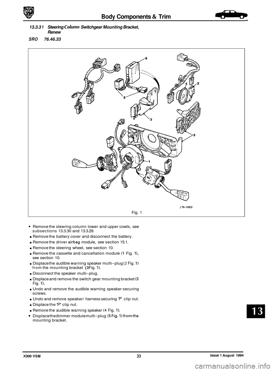
13.3.3 1 Steering Column Switchgear Mounting Bracket,
Renew
SRO 76.46.33
J 76-1 082
Fig. 1
Remove the steering column lower and upper cowls, see
. Remove the battery cover and disconnect the battery.
. Remove the driver airbag module, see section 15.1.
. Remove the steering wheel, see section 10.
. Remove the cassette and cancellation module (1 Fig. I),
. Displace the audible warning speaker multi-plug (2 Fig. 1)
. Disconnect the speaker multi-plug.
. Displace and remove the switch gear mounting bracket (3
. Undo and remove the audible warning speaker securing
. Undo and remove speaker/ harness securing 'P' clip nut.
. Displace the 'P' clip nut.
. Remove the audible warning speaker (4 Fig. 1).
Displacethedimmer modulemulti-plug (5Fig. 1)fromthe
subsections 13.3.30 and 13.3.29.
see section 10.
from the mounting bracket
(3 Fig. 1).
Fig. 1).
screws.
mounting bracket.
issue 1 August 1994 X300 VSM 33
Page 289 of 521
Body Components & Trim
J76-1082
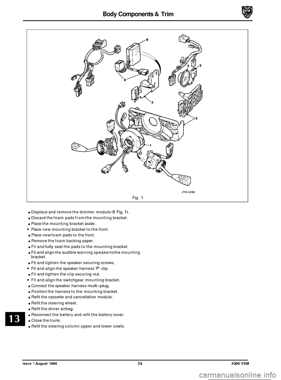
Fig. 1
. Displace and remove the dimmer module (6 Fig. 1).
. Discard the foam pads from the mounting bracket.
. Place the mounting bracket aside.
Place new mounting bracket to the front.
. Place new foam pads to the front.
. Remove the foam backing paper.
. Fit and fully seat the pads to the mounting bracket.
. Fit and align the audible warning speakertothe mounting
bracket.
. Fit and tighten the speaker securing screws.
Fit and align the speaker harness
'F" clip.
. Fit and tighten the clip securing nut.
Fit and align the switchgear mounting bracket.
. Connect the speaker harness multi-plug.
. Position the harness to the mounting bracket.
. Refit the cassette and cancellation module.
. Refit the steering wheel.
. Refit the driver airbag.
. Reconnect the battery and refit the battery cover.
. Close the trunk.
. Refit the steering column upper and lower cowls.
0
0
0
0
Issue 1 August 1994 34 X300 VSM
Page 290 of 521

Body Components & Trim -
13.3.32 'A' Post lower Trim Pad, Renew
SRO 76.13.30
. Locally displace the draught welting from the front door
= Undo and remove the 'A' post lower trim pad quarter turn
. Displace and remove the 'A' post lower trim pad by pulling
. Fit and seat the new 'A' post lower trim pad, engaging the
. Fit and secure the 'A' post lower trim pad quarter turn fas-
Reposition and fully seat the draught welting to the front
aperture
flange.
fastener. rearwards to disengage clips and place aside.
clips on the front door flange.
tener. door aperture flange.
13.3.33 Rear Quarter Upper Trim Pad, Renew
. Remove the rear seat belt upper anchorage RH or LH.
. Remove the trim pad securing screw.
. Slacken but do not remove thecombined grab handle and
. Unclip the rear quarter trim pad and remove.
. To refit, carry out reversal of the above procedure, noting
that seat belt fixings must be tightened to the specified
torque.
coat hook securing screws.
13.3.34 'B' Post Upper Trim Pad, Renew
. Position front seat and squab fully forward.
. Remove seat belt lower anchorage and feed the belt
through the lower trim aperture.
. Remove seat belt upper anchorage.
. Remove trim finisher upper seat belt aperture and door
. Release upper trim pad from its fixings by exerting down-
. To refit, carry out reversal of the above procedure.
aperture edge
trim.
ward pressure.
WARNING: ENSURE THAT THE SEAT BELT IS CORRECTLY
ASSEMBLED AND FlXlNGS TORQUE TIGH-
0 TENED.
13.3.35 'B' Post lower Trim Pad, Renew
. Position front seat and squab fully forward.
Remove seat belt lower anchorage and feed the belt
. Release trim pad quarter turn fasteners and remove trim
Remove fasteners from trim pad as required.
= To refit, carry out reversal of the above procedure.
through the lower
trim aperture.
pad.
WARNING: ENSURE THAT THE SEAT BELT IS CORRECTLY
ASSEMBLED AND FlXlNGS TORQUE TIGH- TENED.
X300 VSM 35 Issue 1 August 1994