JEEP CJ 1953 Service Manual
Manufacturer: JEEP, Model Year: 1953, Model line: CJ, Model: JEEP CJ 1953Pages: 376, PDF Size: 19.96 MB
Page 231 of 376
'Jeep1
UNIVERSAL
SERIES SERVICE
MANUAL
I
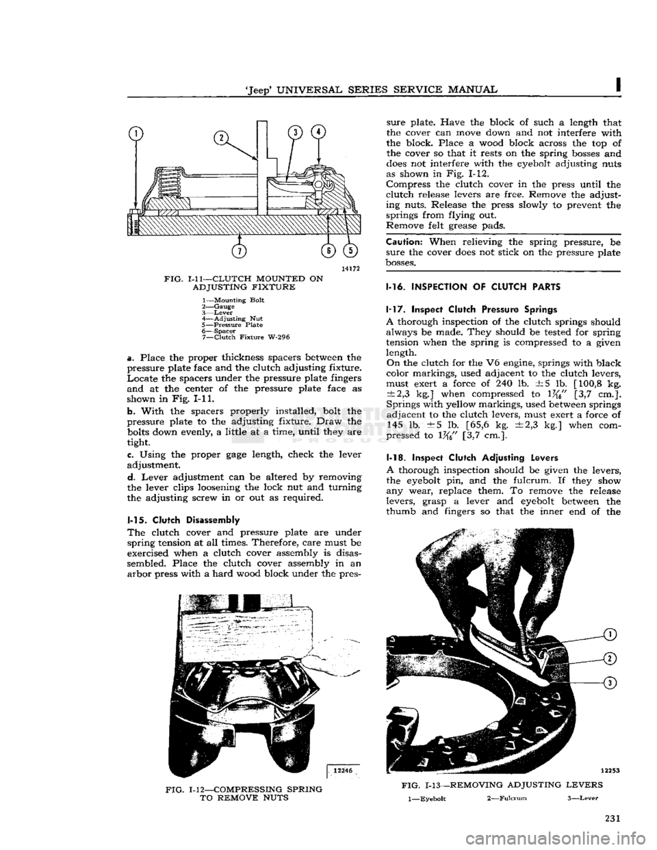
14172
FIG.
1-11—CLUTCH
MOUNTED
ON
ADJUSTING
FIXTURE
1— Mounting Bolt
2—
Gauge
3—
Lever
4—
Adjusting
Nut
5—
Pressure
Plate 6—
Spacer
7—
Clutch
Fixture
W-296
a.
Place the proper thickness
spacers
between the
pressure
plate face and the
clutch
adjusting
fixture.
Locate the
spacers
under the
pressure
plate fingers
and at the center of the
pressure
plate face as
shown
in Fig. I-11.
b.
With
the
spacers
properly installed,
bolt
the
pressure
plate to the adjusting
fixture.
Draw the
bolts
down evenly, a
little
at a
time,
until
they are
tight.
e. Using the proper
gage
length, check the lever
adjustment.
d.
Lever adjustment can be altered by removing
the lever clips loosening the
lock
nut and
turning
the adjusting screw in or out as required.
1-15.
Clutch
Disassembly
The
clutch
cover and
pressure
plate are under
spring
tension at all times. Therefore,
care
must be
exercised when a
clutch
cover assembly is disas
sembled. Place the
clutch
cover assembly in an arbor
press
with
a hard
wood
block under the pres-
FIG.
1-12—COMPRESSING
SPRING
TO
REMOVE
NUTS
sure
plate. Have the block of such a length that
the cover can move down and not interfere
with
the block. Place a
wood
block
across
the top of the cover so that it
rests
on the spring
bosses
and
does
not interfere
with
the eyebolt adjusting nuts
as shown in Fig. 1-12.
Compress the
clutch
cover in the
press
until
the
clutch
release
levers are free. Remove the adjust
ing
nuts.
Release
the
press
slowly
to prevent the
springs
from
flying
out.
Remove
felt
grease
pads.
Caution:
When
relieving
the spring
pressure,
be
sure
the cover
does
not stick on the
pressure
plate
bosses.
1-16.
INSPECTION
OF
CLUTCH
PARTS 1-17. Inspect
Clutch
Pressure
Springs
A
thorough inspection of the
clutch
springs should always be made. They should be tested for spring
tension when the spring is compressed to a given
length.
On
the
clutch
for the V6 engine, springs
with
black
color
markings, used adjacent to the
clutch
levers,
must exert a force of 240 lb. ±5 lb. [100,8 kg.
±2,3
kg.] when compressed to 1%" [3,7 cm.].
Springs
with
yellow
markings, used between springs adjacent to the
clutch
levers, must exert a force of 145 lb. ±5 lb. [65,6 kg. ±2,3 kg.] when com
pressed
to 1%" [3,7 cm.].
1-18. Inspect
Clutch
Adjusting
Levers
A
thorough inspection should be given the levers,
the eyebolt pin, and the
fulcrum.
If they show
any wear, replace them. To remove the
release
levers,
grasp
a lever and eyebolt between the
thumb
and fingers so that the inner end of the
FIG.
1-13—REMOVING
ADJUSTING
LEVERS
l—Eyebolt
2—Fulcrum
3—Lever
231
Page 232 of 376
CLUTCH
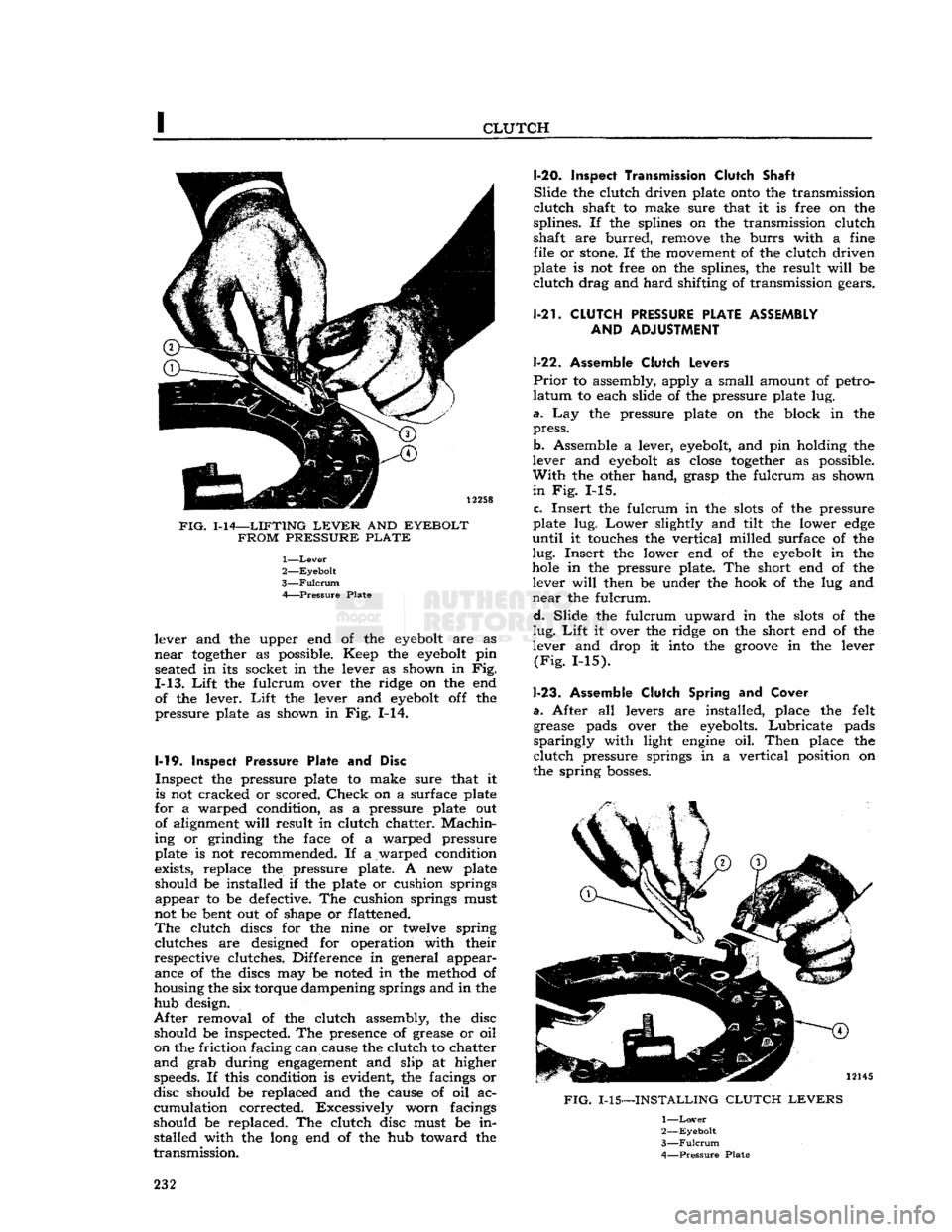
FIG.
1-14—LIFTING
LEVER
AND
EYEBOLT FROM PRESSURE PLATE
1—
Lever
2—
Eyebolt
3—
Fulcrum
A Pressure Plate
lever and the upper end of the
eyebolt
are as
near
together
as possible. Keep the
eyebolt
pin seated in its socket in the lever as shown in Fig.
1-13.
Lift
the fulcrum over the ridge on the end of the lever.
Lift
the lever and
eyebolt
off the
pressure plate as shown in Fig. 1-14.
1-19.
Inspect
Pressure Plate and Disc
Inspect the pressure plate to make sure that it is not cracked or scored.
Check
on a surface plate
for a warped condition, as a pressure plate out of alignment
will
result in clutch chatter.
Machin
ing or grinding the face of a warped pressure
plate is not recommended. If a warped condition
exists, replace the pressure plate. A new plate
should be installed if the plate or cushion springs appear to be defective. The cushion springs must
not be bent out of shape or flattened.
The
clutch discs for the nine or twelve spring clutches are designed for operation with their
respective clutches. Difference in general appear ance of the discs may be noted in the method of
housing the six torque dampening springs and in the
hub design.
After
removal of the clutch assembly, the disc should be inspected. The presence of grease or oil
on the friction facing can cause the clutch to chatter
and
grab during
engagement
and slip at higher speeds. If this condition is evident, the facings or
disc should be replaced and the cause of oil ac
cumulation corrected. Excessively worn facings
should be replaced. The clutch disc must be in stalled with the long end of the hub toward the
transmission.
1-20.
Inspect Transmission Clutch
Shaft
Slide
the clutch driven plate
onto
the transmission
clutch
shaft to make sure that it is free on the
splines. If the splines on the transmission clutch
shaft are
burred,
remove the
burrs
with a fine file or
stone.
If the movement of the clutch driven
plate is not free on the splines, the result
will
be
clutch
drag and
hard
shifting of transmission gears.
1-21.
CLUTCH
PRESSURE
PLATE ASSEMBLY AND
ADJUSTMENT
1-22. Assemble
Clutch
Levers
Prior
to assembly, apply a small amount of petro
latum
to each slide of the pressure plate lug.
a.
Lay the pressure plate on the block in the
press.
b. Assemble a lever,
eyebolt,
and pin holding the
lever and
eyebolt
as
close
together
as possible.
With
the other hand, grasp the fulcrum as shown
in
Fig. 1-15.
c.
Insert the fulcrum in the
slots
of the pressure
plate lug.
Lower
slightly and tilt the lower
edge
until
it touches the vertical milled surface of the
lug.
Insert the lower end of the
eyebolt
in the
hole
in the pressure plate. The short end of the lever
will
then be under the hook of the lug and
near
the fulcrum.
d.
Slide the fulcrum upward in the
slots
of the
lug.
Lift
it over the ridge on the short end of the
lever and drop it into the
groove
in the lever
(Fig.
1-15).
1-23.
Assemble
Clutch
Spring and
Cover
a.
After all levers are installed, place the felt grease pads over the eyebolts.
Lubricate
pads
sparingly
with light
engine
oil.
Then
place the
clutch
pressure springs in a vertical position on
the spring
bosses.
FIG.
1-15—INSTALLING
CLUTCH LEVERS
1—
Lover
2—
Eyebolt
3—
Fulcrum
4—
Pressure
Plate
232
Page 233 of 376
'Jeep*
UNIVERSAL SERIES
SERVICE
MANUAL
b.
Check
the anti-rattle springs in the clutch cover
and
place the cover on top of the pressure plate
assembly. The top of each pressure spring must enter its spring seat in the cover.
Line
up punch
marks
on cover and pressure plate for balance.
c.
Slowly compress the cover making sure that
the
eyebolts
and pressure plate lugs are guided through the proper
holes
in the cover.
d.
Hold the clutch under compression and screw
down the adjusting nuts until they are flush with
the
tops
of the eyebolts. Release the spindle of
the press.
1-24.
Clutch
Lever Adjustment
Important:
Always inspect release lever height
adjustment when installing a new clutch drive
plate.
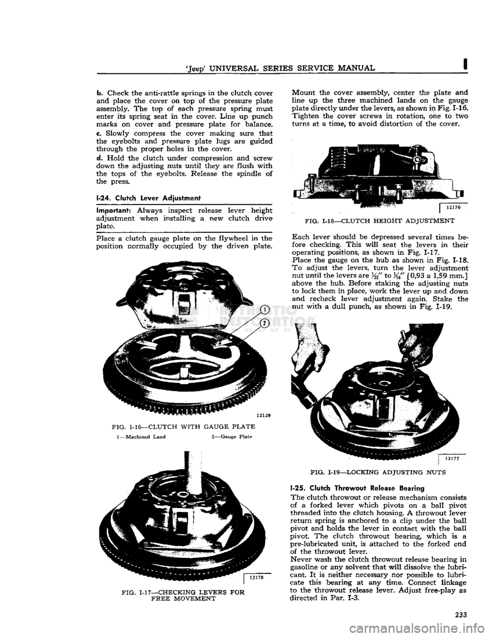
Place
a clutch
gauge
plate on the flywheel in the
position normally occupied by the driven plate.
FIG.
1-16—CLUTCH WITH GAUGE
PLATE
1—Machined
Land
2—Gauge Plate
FIG.
1-17—CHECKING
LEVERS
FOR
FREE
MOVEMENT
Mount
the cover assembly, center the plate and
line up the three machined lands on the
gauge
plate directly under the levers, as shown in
Fig.
1-16.
Tighten
the cover screws in rotation, one to two
turns
at a time, to avoid distortion of the cover.
FIG.
1-18—CLUTCH HEIGHT ADJUSTMENT
Each
lever should be depressed several times be
fore checking.
This
will
seat the levers in their operating positions, as shown in Fig. 1-17.
Place
the
gauge
on the hub as shown in Fig. 1-18.
To
adjust the levers,
turn
the lever adjustment nut until the levers are
%{'
to %6" [0,93 a 1,59 mm.]
above the hub. Before staking the adjusting nuts
to lock them in place, work the lever up and down
and
recheck lever adjustment again. Stake the nut with a
dull
punch, as shown in Fig. 1-19.
FIG.
1-19—LOCKING ADJUSTING NUTS
1-25.
Clutch Throwout
Release Bearing
The
clutch throwout or release mechanism consists
of a forked lever which pivots on a
ball
pivot threaded into the clutch housing. A throwout lever
return
spring is anchored to a clip under the
ball
pivot and holds the lever in contact with the
ball
pivot. The clutch throwout bearing, which is a
pre-lubricated
unit, is attached to the forked end of the throwout lever.
Never wash the clutch throwout release bearing in
gasoline or any solvent that
will
dissolve the
lubri
cant.
It is neither necessary nor possible to
lubri
cate this bearing at any time. Connect linkage
to the throwout release lever. Adjust free-play as
directed
in Par. 1-3. 233
Page 234 of 376
CLUTCH
FIG.
1-20—CLUTCH
REBUILDING
AND
ADJUSTING
FIXTURE
W-296
PIECES
1—Mounting
Fixture
2—Spacers
3—Gauge
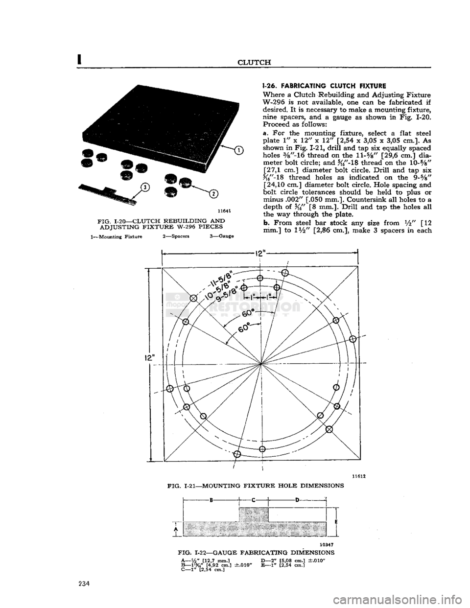
1-26.
FABRICATING CLUTCH FIXTURE
Where
a
Clutch
Rebuilding and Adjusting
Fixture
W-296 is not available, one can be fabricated if
desired.
It is necessary to make a mounting fixture,
nine spacers, and a
gauge
as shown in Fig. 1-20.
Proceed
as follows:
a.
For the mounting fixture, select a flat steel
plate 1" x 12" x 12" [2,54 x 3,05 x 3,05 cm.]. As shown in
Fig.
1-21,
drill
and tap six equally spaced
holes
3/8"-16
thread on the
ll-s/8"
[29,6 cm.]
dia
meter bolt circle; and %"-18 thread on the 10-%" [27,1 cm.] diameter bolt circle.
Drill
and tap six
Jf6"-18
thread
holes
as indicated on the 9-%"
[24,10
cm.] diameter bolt circle. Hole spacing and
bolt circle tolerances should be held to plus or minus .002" [.050 mm.]. Countersink all
holes
to a depth of %" [8 mm.].
Drill
and tap the
holes
all
the way through the plate.
b.
From
steel bar stock any size from V2" [12
mm.] to 1V2" [2,86 cm.], make 3 spacers in each
11612
FIG.
1-21—MOUNTING
FIXTURE HOLE
DIMENSIONS
-B
^ C A D-
10347
FIG.
1-22—GAUGE
FABRICATING
DIMENSIONS
A—1/2"
[12,7 mm.]
B—1%"
[4,92 cm.] "
"' [2,54 cm.]
t.010"
D—2"
[5,08 cm.]
±.010"
£—1"
[2,54 cm.] 234
Page 235 of 376
![JEEP CJ 1953 Service Manual
Jeep
UNIVERSAL
SERIES
SERVICE
MANUAL
I thickness: .285"
[0,724
cm.], .305"
[0,775
cm.].
Each
spacer should be hardened and ground to size, and then have the dimensional thickness
sta JEEP CJ 1953 Service Manual
Jeep
UNIVERSAL
SERIES
SERVICE
MANUAL
I thickness: .285"
[0,724
cm.], .305"
[0,775
cm.].
Each
spacer should be hardened and ground to size, and then have the dimensional thickness
sta](/img/16/57040/w960_57040-234.png)
'Jeep'
UNIVERSAL
SERIES
SERVICE
MANUAL
I thickness: .285"
[0,724
cm.], .305"
[0,775
cm.].
Each
spacer should be hardened and ground to size, and then have the dimensional thickness
stamped thereon.
c.
From
flat bar stock at least Vfe" [3 mm.] thick,
make a
gauge
as shown in Fig. 1-22. Harden, grind
to size, and stamp sizes on the
gauge.
1-27.
Clutch Installation
a.
Very
sparingly, apply wheel bearing lubricant
to inner surface of pilot bushing in crankshaft.
Caution:
If
excessive
lubricant is applied to pilot bushing, it
will
run out on face of flywheel when
hot and
ruin
the driven plate facings.
b. Make sure that splines in the driven plate hub
are
clean; apply a light coat of lubricant to splines
of hub and transmission drive gear shaft. Slide plate over gear shaft several times; remove plate
from shaft and wipe off
excess
lubricant.
Caution:
Driven plate facings must be kept clean
and
dry.
c.
Fill
groove
in throwout bearing collar with wheel bearing lubricant. See Fig. 1-23. Make sure
that front bearing retainer of transmission is clean;
apply a light coat of wheel bearing lubricant. Slide
throwout bearing over bearing retainer several times. Remove bearing from retainer and wipe off
excess
lubricant.
12736
FIG.
1-23—LUBRICATION
POINTS
—
CLUTCH
THROWOUT
BEARING
COLLAR
1—Coat
This
Groove 2—Pack
This
Recess
d.
Clean
and apply wheel bearing lubricant to ball
stud in flywheel housing and to the
seat
in clutch
fork.
e.
If disassembled, install pressure plate in the cover assembly, lining up the
groove
on its
edge
with the
groove
on the
edge
of the cover.
Install
pressure plate retracting springs, and the three
drive
strap-to-pressure plate
bolts
and lock washers.
Torque
bolts
11 lb-ft. [1,51 kg-m.].
Note:
The diaphragm
type
clutch assembly is fac
tory calibrated and requires no adjustment
before
installation. Refer to Par. 1-14 to adjust Borg and
Beck
coil spring
type
clutch assembly.
f.
Install
the pressure plate and driven plate on
flywheel. Support both assemblies with a spare
main
drive gear.
Note:
Be certain that
mark
on clutch cover is
aligned with the
mark
made on the flywheel during
clutch removal.
g.
Install
clutch attaching
bolts
and tighten alter nately so that clutch is drawn squarely
into
position
on flywheel.
Each
bolt
must be
tightened
one turn at a time to avoid bending the clutch cover flange.
Torque
bolts
30 to 40 lb-ft. [4,1 a 5,5 kg-m.].
h.
Lubricate
the ball stud and clutch fork with
wheel bearing lubricant and install clutch fork.
Note:
Be certain that fork retaining spring is
tight
on pivot ball stud.
i.
Install
flywheel housing on
engine
cylinder
block.
Caution:
Be certain that dowel pins are installed
in
cylinder block.
j.
Lubricate
the recess on the inside of the throw-
out bearing collar. Be careful not to use too much
lubricant.
See Fig. 1-23.
Caution:
Make certain that the lips of the spring
retainer (attached to the clutch fork) are in
groove
of the bearing. See Fig. 1-24.
k.
Install
throwout bearing assembly and connect
clutch linkage.
I.
Install
transmission as described in Section J. m. Adjust clutch for %"
[19,05
mm.] free travel,
see
Par.
1-3. 235
Page 236 of 376
CLUTCH
Note:
Should clutch chatter in reverse
develop
on
a
vehicle equipped with the V-6
engine,
installation
of
Anti-Clutch
Chatter Kit,
Part
No.
992824,
will
correct the difficulty. Make certain that the clutch
linkage is
tight
and in proper adjustment.
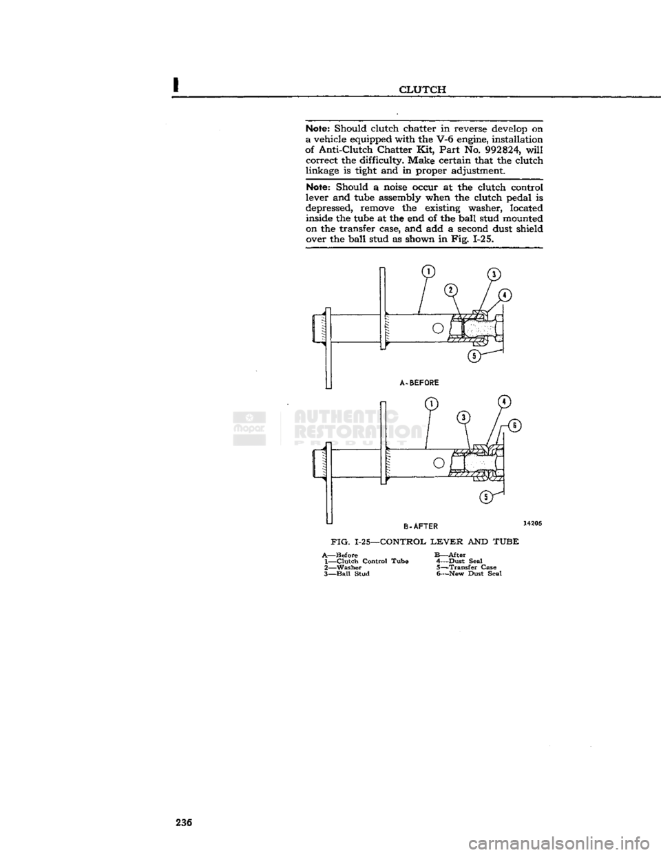
Note:
Should a
noise
occur at the clutch control
lever and
tube
assembly when the clutch pedal is
depressed, remove the existing washer, located inside the
tube
at the end of the
ball
stud mounted
on the transfer case, and add a second dust shield over the
ball
stud as shown in Fig. 1-25. 236
Page 237 of 376
'Jeep'
UNIVERSAL
SERIES
SERVICE
MANUAL
I
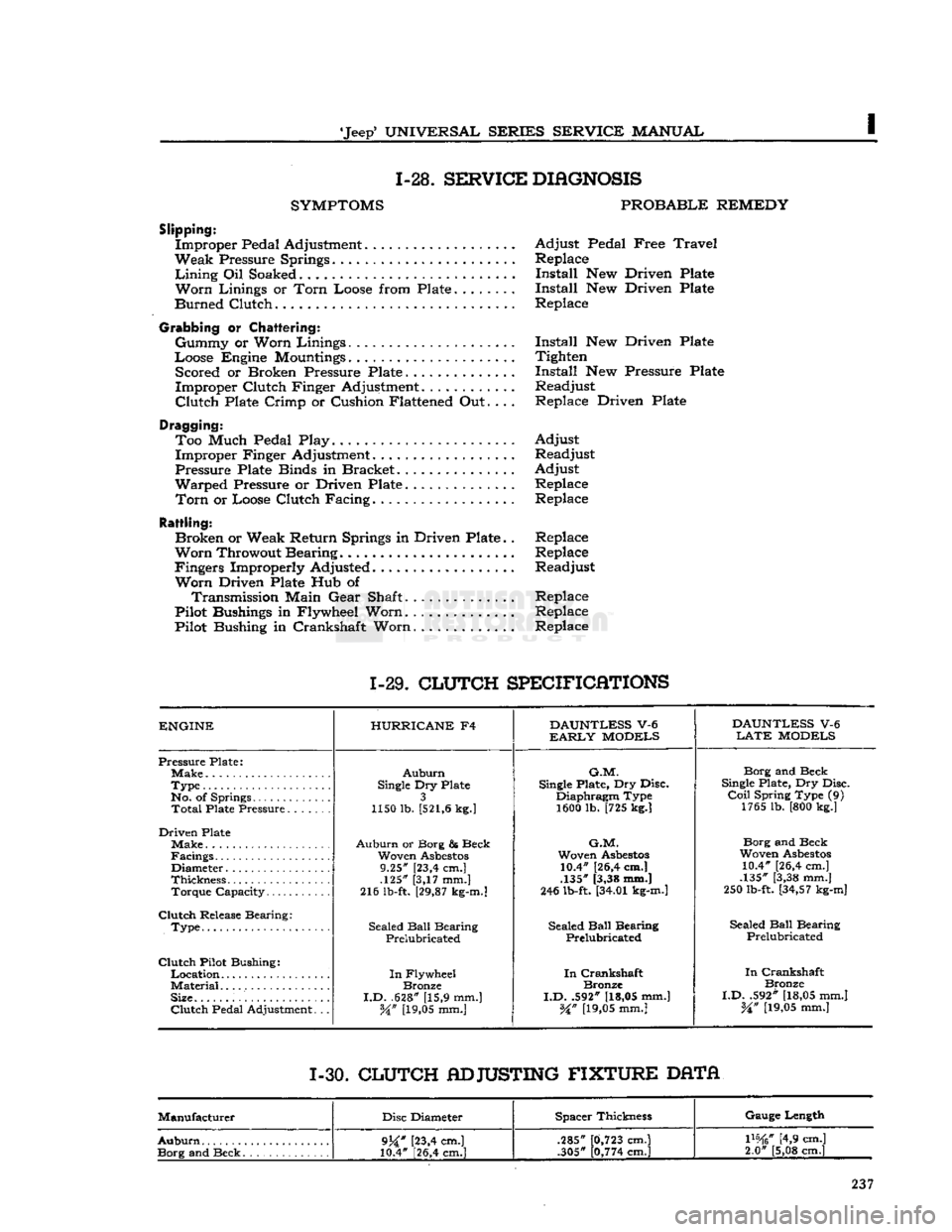
1-28.
SERVICE
DIAGNOSIS
SYMPTOMS
PROBABLE
REMEDY
Slipping:
Improper Pedal Adjustment Adjust Pedal Free
Travel
Weak Pressure Springs Replace
Lining
Oil Soaked Install New Driven Plate
Worn
Linings or
Torn
Loose from Plate Install New Driven Plate
Burned Clutch Replace
Grabbing
or
Chattering:
Gummy or Worn Linings Install New Driven Plate
Loose Engine
Mountings
Tighten Scored or Broken Pressure Plate Install New Pressure Plate
Improper Clutch Finger Adjustment............ Readjust
Clutch
Plate Crimp or Cushion Flattened Out.... Replace Driven Plate
Dragging: Too Much Pedal Play. Adjust Improper Finger Adjustment. Readjust
Pressure Plate Binds in Bracket Adjust
Warped Pressure or Driven Plate Replace
Torn
or Loose Clutch Facing. Replace
Rattling:
Broken or Weak Return Springs in Driven Plate.. Replace
Worn
Throwout Bearing Replace
Fingers Improperly Adjusted Readjust
Worn
Driven Plate Hub of Transmission Main Gear Shaft.............. Replace
Pilot Bushings in Flywheel Worn.
.............
Replace
Pilot Bushing in Crankshaft Worn Replace
1-29.
CLUTCH
SPECIFICATIONS
ENGINE
HURRICANE
F4
DAUNTLESS
V-6
DAUNTLESS
V-6
EARLY
MODELS
LATE
MODELS
Pressure Plate;
Auburn
G.M.
Borg and Beck
Type
Single
Dry Plate
Single
Plate, Dry Disc.
Single
Plate, Dry Disc.
No. of Springs 3 Diaphragm Type
Coil
Spring Type (9)
Total
Plate Pressure 1150 lb.
[521,6
kg.]
1600 lb. [725 kg.] 1765 lb. [800 kg.]
Driven Plate Make
Auburn
or Borg & Beck
G.M.
Borg and Beck
Facings Woven
Asbestos
Woven
Asbestos
Woven
Asbestos
Diameter 9.25" [23,4 cm.] 10.4" [26,4 cm.]
10.4" [26,4 cm.]
Thickness .125" [3,17 mm.] .135" [3,38 mm.]
.135" [3,38 mm.]
Torque Capacity 216 lb-ft.
[29,87
kg-m.]
246 lb-ft.
[34.01
kg-m.]
250 lb-ft.
[34,57
kg-m]
Clutch
Release Bearing: Sealed
Ball
Bearing
.
Type Sealed
Ball
Bearing Sealed
Ball
Bearing Sealed
Ball
Bearing
.
Type
Prelubricated Prelubricated
Prelubricated
Clutch
Pilot Bushing:
In
Crankshaft
In
Flywheel
In
Crankshaft
In
Crankshaft
Material
Bronze Bronze
Bronze
Size.
I.D.
.628" [15,9 mm.]
I.D.
.592"
[18,05
mm.]
I.D.
.592"
[18,05
mm.]
Clutch
Pedal Adjustment. .. W
[19,05
mm.]
%n
[19,05
mm.]
%n
[19,05
mm.]
1-30.
CLUTCH
ADJUSTING
FIXTURE
DATA
Manufacturer Disc Diameter Spacer Thickness Gauge Length
Auburn
9j£"
[23,4 cm.]
10.4" [26,4 cm.] .285"
.305"
0,723
cm.]
0,774
cm.]
mtf
[4,9 cm.]
2.0" [5,08 cm.]
9j£"
[23,4 cm.]
10.4" [26,4 cm.] .285"
.305"
0,723
cm.]
0,774
cm.]
mtf
[4,9 cm.]
2.0" [5,08 cm.]
Page 238 of 376

Page 239 of 376
'Jeep'
UNIVERSAL
SERIES
SERVICE
MANUAL
J
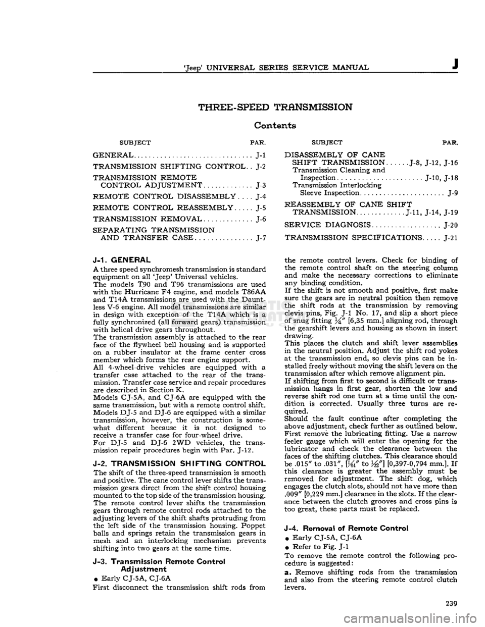
THREE-SPEED
TRANSMISSION
Contents
SUBJECT
PAR.
GENERAL
J-l
TRANSMISSION
SHIFTING
CONTROL.
. J-2
TRANSMISSION
REMOTE
CONTROL
ADJUSTMENT
J-3
REMOTE
CONTROL
DISASSEMBLY
J-4
REMOTE
CONTROL
REASSEMBLY.
. . . . J-5
TRANSMISSION
REMOVAL
J-6
SEPARATING
TRANSMISSION
AND
TRANSFER
CASE
J-7
SUBJECT
PAR.
DISASSEMBLY
OF
CANE
SHIFT
TRANSMISSION
J-8, J-12, J-16
Transmission
Cleaning and
Inspection J-10, J-18
Transmission
Interlocking Sleeve Inspection J-9
REASSEMBLY
OF
CANE
SHIFT
TRANSMISSION
J-ll,
J-14, J-19
SERVICE
DIAGNOSIS
J-20
TRANSMISSION
SPECIFICATIONS
J-21
J-1.
GENERAL
A
three speed synchromesh transmission is standard
equipment on all 'Jeep' Universal vehicles.
The
models T90 and T96 transmissions are used
with
the
Hurricane
F4 engine, and models
T86AA
and
T14A transmissions are used with the Daunt
less
V-6 engine. All model transmissions are similar
in
design with exception of the T14A which is a
fully
synchronized (all forward gears) transmission
with
helical drive gears throughout.
The
transmission assembly is attached to the
rear
face of the flywheel bell housing and is supported on a rubber insulator at the frame center cross member which forms the
rear
engine
support.
All
4-wheel-drive vehicles are equipped with a
transfer
case attached to the
rear
of the transmission.
Transfer
case service and repair procedures
are
described in Section
K.
Models
CJ-5A,
and
CJ-6A
are equipped with the
same transmission, but with a remote control shift.
Models DJ-5 and DJ-6 are equipped with a similar
transmission,
however, the construction is
some
what different because it is not designed to receive a transfer case for four-wheel drive.
For
DJ-5 and DJ-6 2WD vehicles, the trans mission repair procedures begin with Par. J-12.
J-2.
TRANSMISSION SHIFTING CONTROL
The
shift of the three-speed transmission is smooth
and
positive. The cane control lever shifts the trans
mission gears direct from the shift control housing
mounted to the top side of the transmission housing.
The
remote control lever shifts the transmission
gears through remote control rods attached to the
adjusting
levers of the shift shafts protruding from the left side of the transmission housing. Poppet
balls and springs retain the transmission gears in mesh and an interlocking mechanism prevents
shifting into two gears at the same time.
J-3.
Transmission Remote Control Adjustment
•
Early
CJ-5A,
CJ-6A
First
disconnect the transmission shift rods from the remote control levers.
Check
for binding of
the remote control shaft on the steering column
and
make the necessary corrections to eliminate any binding condition.
If
the shift is not smooth and positive, first make
sure
the gears are in neutral position then remove
the shift rods at the transmission by removing
clevis pins, Fig. J-l No. 17, and slip a short piece
of snug fitting 34" [6,35 mm.] aligning rod, through
the gearshift levers and housing as shown in insert
drawing.
This
places the clutch and shift lever assemblies
in
the neutral position. Adjust the shift rod yokes
at the transmission end, so clevis pins can be in stalled freely without moving the shift levers on the
transmission after which remove alignment pin.
If
shifting from first to second is difficult or trans
mission hangs in first gear, shorten the low and
reverse shift rod one
turn
at a time until the con
dition is corrected. Usually three turns are re
quired.
Should
the fault continue after completing the above adjustment, check further as outlined below.
First
remove the lubricating fitting. Use a narrow
feeler
gauge
which
will
enter the opening for the
lubricator
and check the clearance
between
the
faces of the shifting clutches.
This
clearance should
be .015" to .031", [W to W]
[0,397-0,794
mm.]. If
this clearance is greater the assembly must be removed for adjustment. The shift dog, which
engages
the clutch slots, should not have more than .009" [0,229 mm.] clearance in the slots. If the clear
ance
between
the clutch
grooves
and cross pins is
too great,
these
parts must be replaced.
J-4.
Removal
of
Remote Control
m
Early
CJ-5A,
CJ-6A
•
Refer to Fig. J-l
To
remove the remote control the following pro cedure is
suggested:
a.
Remove shifting rods from the transmission
and
also from the steering remote control clutch levers. 239
Page 240 of 376
THREE-SPEED
TRANSMISSION
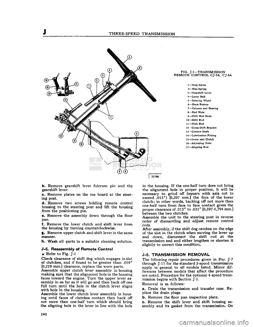
FIG.
J-l—TRANSMISSION
REMOTE
CONTROL
CJ-5
A,
CJ-6A
1— Stop Screw
2—
Bias
Spring
3—
Gearshift
Lever
4—
Lever
Ball
5—
Steering
Wheel 6—
Horn
Button 7—
Column
and Bearing
8—
End
Huts
9—
Shift
Rod
Ends
10—
Shift
Rod
11—
Shift
Rod
12—
Cross-Shift
Bracket
13—
Control
Shaft
14—
Lubrication
Fitting
15—
Lever
and
Clutch
16—
Adjusting
Yoke
17—
Aligning
Rod 11706
b.
Remove gearshift lever fulcrum pin and the
gearshift lever.
c.
Remove plates on the toe board at the steer
ing
post.
d.
Remove two screws holding remote control
housing to the steering
post
and lift the housing
from
the positioning pin.
e.
Remove the assembly down through the floor
pan.
f. Remove the lower clutch and shift lever from the housing by turning counterclockwise.
g. Remove upper clutch and shift lever in the same
manner.
h. Wash all parts in a suitable cleaning solution.
J-5.
Reassembly of
Remote
Control
•
Refer to
Fig.
J-l
Check
clearance of shift dog which
engages
in slot
of clutches, and if found to be greater than .009" [0,229 mm.] clearance, replace the worn parts.
Assemble upper clutch lever assembly in housing
making
sure that the alignment
hole
in the housing
faces toward the engine.
Turn
the upper lever as
sembly in as far as it
will
go and then back off one
full
turn
until the
hole
in the clutch lever aligns
with
hole
in the housing.
Assemble the lower clutch lever assembly in hous ing until faces of clutches contact then back off
not more than one-half
turn
which should bring
the aligning
hole
in the lever in line with the
hole
in
the housing. If the one-half
turn
does
not bring
the alignment
hole
in proper position, it
will
be
necessary to grind off (square with axis not to exceed .015") [0,397 mm.] the face of the lower
clutch;
in other words, backing off not more than
one-half
turn
from face to face contact
gives
the
proper
clearance of .015" to .031"
[0,397-0,794
mm.]
between
the two clutches.
Assemble the unit to the steering
post
in reverse
order
of dismantling and adjust remote control
rods.
After
assembly, if the shift dog catches on the
edge
of the slot in the clutch when moving the lever up
and
down, disconnect the shift rod at the
transmission
end and either lengthen or shorten it
slightly to correct this condition.
J-6.
TRANSMISSION
REMOVAL
The
following repair procedures given in Par. J-7
through J-ll for the standard
3-speed
transmission
apply
in general to all models listed. Minor dif
ferences
between
models that affect the procedure
are
noted. Procedure for the optional
4-speed
transmission
begins
with Section
J-l.
Removal
is as follows:
a.
Drain
the transmission and transfer case. Re place the
drain
plugs.
b.
Remove the floor pan inspection plate.
c.
Remove the shift lever and shift housing as sembly and its gasket from the transmission. On 240