JEEP CJ 1953 Service Manual
Manufacturer: JEEP, Model Year: 1953, Model line: CJ, Model: JEEP CJ 1953Pages: 376, PDF Size: 19.96 MB
Page 271 of 376
'Jeep'
UNIVERSAL SERIES SERVICE
MANUAL
K
the
bottom.
Remove
rear
bearing
cone
and roller
assembly from the shaft by striking the end of the
shaft lightly against a
wooden
block,
j.
Remove the set screw in sliding gear shift fork.
Remove shift rod.
See the following paragraphs for disassembly of
the front and
rear
bearing caps.
K-4.
Front
Bearing Cap Disassembly
•
Refer to Fig. K-1, K-2.
The
front bearing cap is a separate assembly which
may
be removed for service. Should difficulty be
experienced in this section of the transfer case,
follow
the
sequence
below
for removal and dis assembly.
a.
Remove the output shaft yoke as outlined in
Par. K-3.
Remove the
poppet
balls and
move
the
front wheel drive shift rod forward as outlined in
Par.
K-3f.
b.
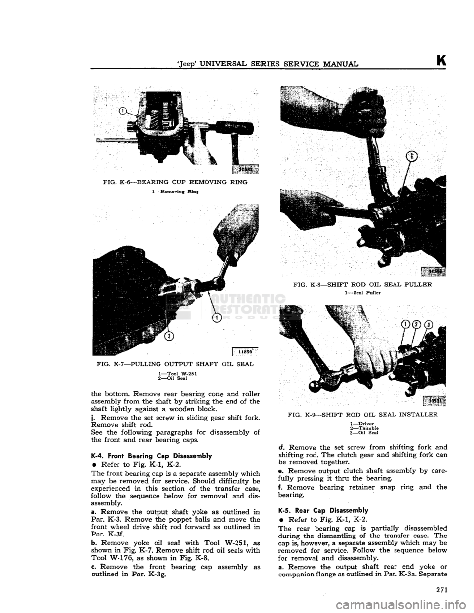
Remove yoke oil seal with Tool W-251, as shown in Fig.
K-7.
Remove shift rod oil seals with
Tool
W-176, as shown in Fig. K-8.
c.
Remove the front bearing cap assembly as outlined in Par. K-3g.
FIG.
K-9—SHIFT
ROD OIL
SEAL INSTALLER
1—
Driver
2—
Thimble
3— Oil
Seal
d.
Remove the set screw from shifting fork and
shifting rod. The clutch gear and shifting fork can
be removed
together.
e. Remove output clutch shaft assembly by care
fully
pressing it
thru
the bearing.
f. Remove bearing retainer snap ring and the
bearing.
K-5.
Rear
Cap Disassembly
•
Refer to Fig. K-1, K-2.
The
rear
bearing cap is partially disassembled
during
the dismantling of the transfer case. The
cap is, however, a separate assembly which may be
removed for service. Follow the
sequence
below
for removal and disassembly,
a.
Remove the output shaft
rear
end yoke or
companion
flange
as outlined in
Par. K-3 a.
Separate 271
Page 272 of 376
K
TRANSFER
CASE
the brake drum and companion
flange
by remov
ing bolts, lockwashers, and nuts.
b.
Remove the oil seal with Tool W-251, as shown
in
Fig. K-7.
c.
Remove
speedometer
driven gear assembly.
d.
Remove the cap screws attaching the cap and
brake
backing plate to the case.
Take
precautions
not to
lose
or damage bearing adjusting shims placed
between
the cap and the transfer case
housing.
e. Separate the
rear
cap and brake backing plate
assembly. See Section P for brake service pro
cedures.
f. Remove
speedometer
driving gear.
K-6.
Transfer
Case
Reassembly
•
Refer to Fig. K-1, K-2.
Reassembly
of the transfer case is reversal of the
foregoing
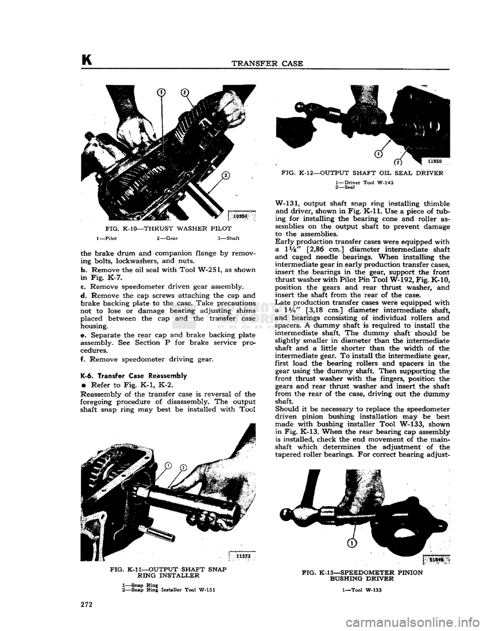
procedure of disassembly. The output shaft snap ring may
best
be installed with Tool
FIG.
K-11—OUTPUT
SHAFT
SNAP
RING
INSTALLER
1—
Snap
Ring
2—
Snap
Ring
Installer Tool W-131
FIG.
K-12—OUTPUT
SHAFT
OIL
SEAL
DRIVER
1—
Driver
Tool W-143
2—
Seal
W-131,
output shaft snap ring installing thimble
and
driver,
shown in
Fig.
K-ll.
Use a
piece
of tub
ing for installing the bearing
cone
and roller as semblies on the output shaft to prevent damage
to the assemblies.
Early
production transfer cases were equipped with
a
lVs" [2,86 cm.] diameter intermediate shaft
and
caged
needle
bearings. When installing the intermediate gear in early production transfer cases,
insert
the bearings in the gear, support the front
thrust
washer with Pilot Pin Tool W-192,
Fig.
K-10,
position the gears and
rear
thrust washer, and
insert
the shaft from the
rear
of the case.
Late
production transfer cases were equipped with
a
1
Vi"
[3,18 cm.] diameter intermediate shaft,
and
bearings consisting of individual rollers and
spacers.
A dummy shaft is required to install the
intermediate shaft. The dummy shaft should be slightly smaller in diameter than the intermediate
shaft and a little shorter than the width of the
intermediate gear. To install the intermediate gear,
first
load the bearing rollers and spacers in the gear using the dummy shaft.
Then
supporting the
front thrust washer with the fingers, position the gears and
rear
thrust washer and insert the shaft
from
the
rear
of the case, driving out the dummy
shaft.
Should
it be necessary to replace the
speedometer
driven
pinion bushing installation may be
best
made with bushing installer Tool W-133, shown
in
Fig. K-13. When the
rear
bearing cap assembly
is installed, check the end
movement
of the main-
shaft which determines the adjustment of the
tapered roller bearings. For correct bearing adjust-
|
11S4S
FIG.
K-13—SPEEDOMETER
PINION
BUSHING
DRIVER
1—Tool W-133
272
Page 273 of 376
![JEEP CJ 1953 Service Manual
Jeep*
UNIVERSAL
SERIES
SERVICE
MANUAL
K
ment, the shaft should have .004" to .008"
[0,102
a
0,203
mm.] end play. Adjustment is made by
selective
shim installation
between
the cap an JEEP CJ 1953 Service Manual
Jeep*
UNIVERSAL
SERIES
SERVICE
MANUAL
K
ment, the shaft should have .004" to .008"
[0,102
a
0,203
mm.] end play. Adjustment is made by
selective
shim installation
between
the cap an](/img/16/57040/w960_57040-272.png)
'Jeep*
UNIVERSAL
SERIES
SERVICE
MANUAL
K
ment, the shaft should have .004" to .008"
[0,102
a
0,203
mm.] end play. Adjustment is made by
selective
shim installation
between
the cap and the
case. Shims .003", .010" and .031" [0,076,
0,254,
0,787
mm.] in thickness are available for this ad
justment. Do not install the rear cap oil seal until
the bearings are correctly adjusted. Both the front
and
rear oil seals may be installed with oil seal
driver
Tool W-143, shown in Fig. K-12.
When
installing the end yokes on the output shafts,
inspect for the presence of
felt
seals in each oil
seal guard. (The oil seal guard is a part of each
yoke assembly.) Felt seals should be installed in the oil seal guards if
they
are not present. When
installing the shift
rail
oil seals in the front bear
ing cap, it is necessary to protect the seals against
damage when passing over the shift
rail
notches.
Protect them with the thimble, and install them with the driver, Tool W-130, shown in Fig. K-9.
K-7.
Transfer Case Installation
The
installation of the assembly in the vehicle is
the reverse of the removal operation covered in
Par.
K-2.
If
the transmission was removed from the vehicle,
lubricate the pilot bearing and also lubricate the
transmission and transfer case as outlined in the
"Lubrication
Section". Be sure that the clutch pedal has %"
[19,05
mm.] free travel as outlined
in
the
"Clutch
Section".
K-8.
Transfer Case Linkage Adjustment
Adjust
the link to provide
xh"
[12,7 mm.] clear
ance
between
the floor pan and the shift lever
bend when operating in four wheel drive low
position. Refer to Fig. K-4.
K-3.
TRENSFER
CESE
SERVICE
DIAGNOSIS
SYMPTOMS PROBABLE REMEDY
Slips
Out of
Gear (High-Low)
Shifting
Lock
Spring Weak Replace Spring
Bearing
Broken or Worn Replace
Shifting
Fork
Bent Replace
Slips
Out of
Front Wheel Drive
Shifting
Lock
Spring Weak. Replace
Bearing
Worn or Broken Replace
End
Play in Shaft. . . ..... Adjust Shifting
Fork
Bent.. Replace
Hard Shifting
Lack
of
Lubricant
Drain
and
Refill
Shift
Lever
Stuck on Shaft Remove, Clean and Lubricate
Shifting
Lock
Ball
Scored Replace
Ball
Shifting
Fork
Bent Replace
Fork
Low
Tire
Pressure Inflate
Grease Leak
at
Front
or
Rear Drive
Grease
Leak
at Covers. Install New Gaskets
Grease
Leak
between
Transmission and Transfer Cases Install New Gaskets
Grease
Leak
at Output Shaft Install New Oil Seal
K-10.
TRANSFER
CESE
SPECIFICATIONS
Transfer
Case:
All
Models
Spicer
18
On
Floor
Gear
Ratio: 1.00 to 1
2.46 to 1 273
Page 274 of 376

Page 275 of 376
'Jeep*
UNIVERSAL
SERIES
SERVICE
MANUAL
L
PROPELLER
SHAFTS
AND
UNIVERSAL JOINTS
Contents
SUBJECT
PAR.
GENERAL
L-l
Needle
Bearing and Trunnion. . . L-2
Snap Ring Type Assembly L-4
Snap Ring Type Disassembly. . L-3
U-Bolt
Type Assembly L-6
U-Bolt
Type Disassembly .L-5
PROPELLER
SHAFTS
AND
UNIVERSAL JOINTS SPECIFICATIONS
L-7
L-1. GENERAL
The
drive of 'Jeep* 4-wheel-drive Universal
models
from the transfer case to the front and rear axles is through two tubular propeller shafts, each shaft having two cardan cross universal joints. The drive
of 'Jeep' 2-wheel-drive
models
from the transmission to the rear axle is through a tubular pro
peller shaft having two cardan cross universal
joints.
Propeller shafts and universal joints should be
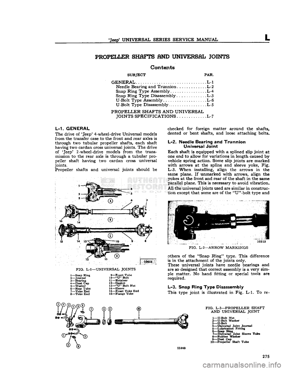
10603
FIG.
L-l—UNIVERSAL JOINTS
1— Snap Ring
2—
Journal
3—
Bearing
4— Dust Cap
5—
Washer
6—
Rear
Tube 7—
Yoke
End
8—
Yoke
End
9—Front
Tube
10—
"U"
Bolt
11—
Retainer
12—
Gasket
13—
"U"
Bolt Nut
14—
Sleeve
15—
Front
Yoke End
16— Flange Yoke checked for foreign matter around the shafts,
dented
or
bent
shafts, and
loose
attaching
bolts.
L-2.
Needle Bearing
and
Trunnion Universal Joint
Each
shaft is equipped with a splined slip joint at one end to allow for variations in
length
caused by vehicle spring action.
Some
slip joints are marked
with arrows at the spline and
sleeve
yoke, Fig.
L-3.
When installing, align the arrows in the
same plane. If unmarked with arrows, align the
yokes
at the front and rear of the shaft in the same
parallel
plane. This is necessary to avoid vibration.
All
the universal joints used are similar in construc
tion
except
that
some
are of the "U"-bolt
type
and 10315
FIG.
L-2—ARROW MARKINGS
others of the "Snap Ring'* type. This difference
is in the attachment of the joints only. These universal joints have
needle
bearings and
are
so
designed
that correct assembly is a very sim
ple matter. No hand fitting or special
tools
are
required.
L-3.
Snap Ring Type Disassembly
This
type
joint is illustrated in Fig.
L-l.
To re-
FIG.
L-3—PROPELLER
SHAFT AND UNIVERSAL JOINT
1—
U-Bolt
Nut
2—
U-Bolt
Washer
3—U-Bolt
4—
Universal
Joint Journal 5—
Lubrication
Fitting 6— Snap Ring 7—
Universal
Joint
Sleeve
Yoke
8—
Rubber
Washer
9— Dust Cap
10—Propeller Shaft Tube 11440
275
Page 276 of 376
L
PROPELLER
SHAFTS
AND
UNIVERSAL JOINTS
move
the snap rings, pinch the ends
together
with
a
pair
of pliers. If the rings do not readily snap
out of the groove, tap the end of the bearing lightly
which
will
relieve pressure against the rings.
After
removing the snap rings, press on the end of
one bearing until the
opposite
bearing is pushed
from
the yoke arm.
Turn
the joint over and press
the first bearing back out of that arm by pressing
on the
exposed
end of the
journal
shaft. Use a
soft
ground drift with a flat face about [0,8 mm.]
smaller
in diameter than the
hole
in the yoke arm
and
drive it out, otherwise there is danger of damaging the bearing.
Repeat
this operation for the other two bearings,
then lift out
journal
assembly by sliding it to one
side.
L-4.
Snap
Ring
Type Assembly
Wash
all parts in cleaning solvent and inspect the
parte
after cleaning. Replace any parts that indicate
extensive
wear.
It is advisable to install new gaskets
on the
journal
assembly regardless of the condition of the old gaskets. Make certain that the grease
channel
in each
journal
trunnion is open.
Pack
the bearing
cones
one-third
full
of lubricant
and
install the rollers.
Draw
the bearings into the end yoke arm and seat
them firmly against the bearing shoulders. Hold
the bearings in a vertical position to prevent the
needles
from dropping out until the joint is as sembled. If the joint binds when assembled, tap
the arms lightly to relieve any pressure on the bear
ings at the end of the
journal.
L-5.
U-Bolt
Type Disassembly
Removal
of the attaching "U"-bolt releases one set
of bearing races. Slide the propeller shaft into the
yoke flange to remove them using care not to
lose
the rollers.
After
the removal of the one set of bearing races,
release the other set by removing the snap rings
in
the
sleeve
yoke by pinching the ends
together
with
a
pair
of pliers. Should the rings
fail
to snap
readily
from the groove, tap the end of the bearing
lightly,
which
will
relieve the pressure against them.
Press
on the end of one bearing, until the
opposite
bearing
is pushed out of the yoke arm.
Turn
the
universal
joint over and press the first bearing out
by pressing on the
exposed
end of the
journal
as
sembly. Use a
soft
ground drift with a flat face about
\{i
[0,8 mm.] smaller in diameter than the
hole
in the yoke
arm
and drive out the bearing.
Lift
the
journal
out by sliding to one side.
Clean
all
parts
and check for wear.
L-6.
U-Bolt Type Assembly
Wash
all parts in cleaning solvent and inspect the
parts
after cleaning. Replace any parts that indicate
extensive
wear.
It is advisable to install new gaskets
on the
journal
assembly regardless of the condition
of the old gaskets. Make certain that the grease
channel
in each
journal
trunnion is open.
Pack
the bearing
cones
one-third
full
of lubricant
and
install the rollers.
Draw
the bearings into the end yoke arm and seat
them firmly against the bearing shoulders. Hold the
bearings in a vertical position to prevent the
needles
from dropping out until the joint is as
sembled. If the joint binds when assembled, tap the arms lightly to relieve any pressure on the
bearings at the end of the
journal.
Tighten the
U-bolts equally. U-bolt torque wrench reading is 15 to 20 lb-ft. [2,07 a 2,76 kg-m.].
When
installing the assembly in the vehicle be sure
that the arrows on the propeller shaft and yoke
sleeve
are in alignment as shown in Fig. L-2, or
that the unmarked joints are aligned with the yokes in the same parallel plane.
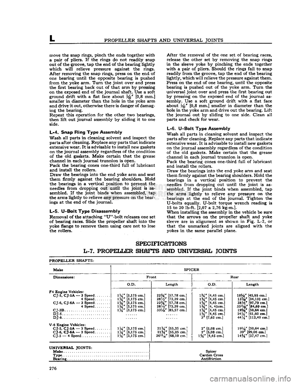
SPECIFICATIONS
L-7.
PROPELLER
SHAFTS
AND
UNIVERSAL JOINTS
PROPELLER
SHAFTS:
Make
SPICER
Dimensions:
F4
Engine Vehicles:
CJ-5,
CJ-5
A
— 3 Speed.
......
4 Speed
CJ-6,
CJ-6A
— 3 Speed 4 Speed
CJ-3B
DJ-5
DJ-6.
V-6
Engine Vehicles:
CJ-5,
CJ-5A
— 3 Speed.
CJ-6,
CJ-6A
— 3 Speed.
CJ-5
— 4 Speed
Front
Rear
Dimensions:
F4
Engine Vehicles:
CJ-5,
CJ-5
A
— 3 Speed.
......
4 Speed
CJ-6,
CJ-6A
— 3 Speed 4 Speed
CJ-3B
DJ-5
DJ-6.
V-6
Engine Vehicles:
CJ-5,
CJ-5A
— 3 Speed.
CJ-6,
CJ-6A
— 3 Speed.
CJ-5
— 4 Speed
O.D.
Length
O.D.
Length
Dimensions:
F4
Engine Vehicles:
CJ-5,
CJ-5
A
— 3 Speed.
......
4 Speed
CJ-6,
CJ-6A
— 3 Speed 4 Speed
CJ-3B
DJ-5
DJ-6.
V-6
Engine Vehicles:
CJ-5,
CJ-5A
— 3 Speed.
CJ-6,
CJ-6A
— 3 Speed.
CJ-5
— 4 Speed
1M"
[3,175 cm.]
1M*
[3,175 cm.]
\W
[3,175 cm.]
1M*
[3,175 cm.] [3,175 cm.]
\W
[3,175 cm.]
\W
[3,175 cm.] [3,175 cm.] 22^" [57,78 cm.]
28H"
[72,39 cm.]
22M*
[57,78 cm.]
mW
[72,39 cm.]
33He"
[85,57 cm.]
21W
[55,25 cm.]
21%"
[55,25 cm.]
2&*
cm.]
IK"
[4,45 cm.]
1M#
[4,45 cm.]
\%"
[4,45 cm.]
\%"
[4, 45cm.]
IW
[4,45 cm.]
1M*
[4,45 cm.]
3*
[7,62 cm.]
2" [5,08 cm.]
2" [5,08 cm.]
l%" [4,45 cm.]
182£"
[45,95 cm.]
WW
[34,131
cm.]
3SJ4*
[97,79 cm.]
33%"
[84,69 cm.] 19546*
[50,64
cm.]
24^"
[61,60
cm.]
44M*
[112,40
cm.]
19%?
[50,64
cm.] 39* [99,06 cm.]
U%"
[37,47 cm.l
UNIVERSAL
JOINTS:
Make
Spicer
Cardan
Cross
Antifriction
Type
Spicer
Cardan
Cross
Antifriction
Bearing
Spicer
Cardan
Cross
Antifriction
276
Page 277 of 376
'Jeep*
UNIVERSAL SERIES SERVICE
MANUAL
m
FRONT fiXLE
Contents
SUBJECT
PAR.
GENERAL.
M-l
4-WHEEL DRIVE FRONT
AXLE.
M-2
Maintenance
Requirements M-3
FRONT AXLE REMOVAL
.M-4
AXLE
SHAFT REMOVAL
M-5
REMOVING
AND
OVERHAULING
DIFFERENTIAL
.M-6
AXLE
SHAFT UNIVERSAL JOINT SERVICE
M-7
STEERING
KNUCKLE SERVICE
M-8
Replacing
Steering
Knuckle
Oil Seal M-10
M-1. GENERAL
The
front axle for all 'Jeep* Universal models,
which
have 4-wheel drive, is described in
Par.
M-2.
The
front axle for all DJ-5, DJ-6 models, which
have 2-wheel drive, is described in
Par.
M-l5.
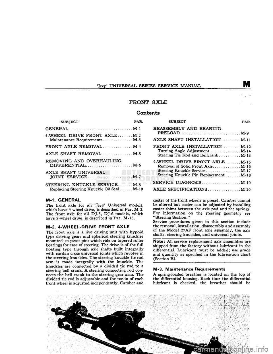
M-2. 4-WHEEL-DRIVE FRONT AXLE
The
front axle is a live driving unit with hypoid
type
driving gears and spherical steering knuckles mounted m pivot pins which ride on tapered roller bearings for
ease
of steering. The drive is of the
full
floating
type
through axle shafts built integrally
with
cardan cross universal joints which revolve in the steering knuckles. The steering knuckle tie rod
arm
is made integrally with the knuckle. The
knuckles
are connected by a divided tie rod to a steering bell
crank.
A steering connecting rod con
nects
the bell
crank
to the steering gear arm. The
divided
tie rod is adjustable and the
toe-in
of each
front wheel is adjusted independently.
Camber
and
SUBJECT
PAR.
REASSEMBLY
AND
BEARING PRELOAD
M-9
AXLE
SHAFT INSTALLATION
M-ll
FRONT AXLE INSTALLATION........
.M-l2
Turning
Angle Adjustment . .M-14
Steering
Tie Rod and
Beilcrank
M-l3
2-WHEEL DRIVE FRONT AXLE
M-15
Removal
of Solid
Front
Axle M-l6
Steering
Knuckle
Service M-l7
Steering
Knuckle
Pin Replacement. ......M-l8
SERVICE
DIAGNOSIS
M-19
AXLE
SPECIFICATIONS.
M-20
caster
of the front
wheels
is preset.
Camber
cannot
be altered but caster can be adjusted by installing
caster
shims
between
the axle pad and the springs.
For
information on the steering
geometry
see
"Steering
Section."
Service
procedures given in this section include
the removal, installation, disassembly and assembly
of the Model
27AF
front axle assembly, the axle
shafts, steering knuckles, and
universal
joints.
Note:
All service replacement axle assemblies are
shipped from the factory without lubricant in the
differential.
Lubricant
must be added; use grade
and
quantity as specified in the lubrication chart (Section B).
M-3.
Maintenance Requirements
A
spring-loaded breather is located on the top of
the differential housing.
Each
time the differential
lubricant
is checked, the breather should be
Page 278 of 376
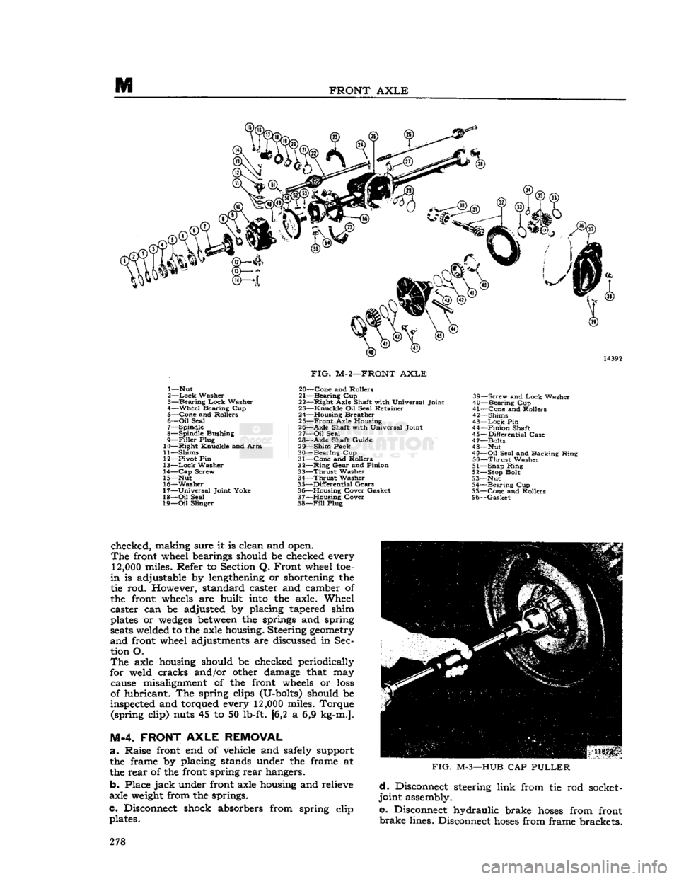
M
FRONT
AXLE
1— Nut
2—
Lock
Washer
3—
Bearing
Lock
Washer
4—
Wheel
Bearing Cup 5—
Cone
and Rollers
6—
Oil
Seal 7— Spindle
8— Spindle Bushing
9—
Filler
Plug
10—
Right
Knuckle and Arm
11— Shims
12— Pivot Pin
13—
Lock
Washer
14—
Cap
Screw
15— Nut
16—
Washer
17—
Universal
Joint Yoke
18—
Oil
Seal
19—
Oil
Slinger
FIG.
M-2—FRONT
AXLE
20—
Cone
and Rollers
21—
Bearing
Cup
22—
Right
Axle Shaft with Universal Joint
23—
Knuckle
Oil Seal Retainer
24— Housing Breather 25—
Front
Axle Housing
26—
Axle
Shaft with Universal Joint
27—
Oil
Seal
28—
Axle
Shaft Guide
29—
Shim
Pack
30—
Bearing
Cup
31—
Cone
and Rollers
32—
Ring
Gear
and Pinion
33—
Thrust
Washer
34—
Thrust
Washer
35—
Differential
Gears
36— Housing Cover Gasket
37— Housing Cover
38—
Fill
Plug 39—
Screw
and
Lock
Washer
40—
Bearing
Cup
41—
Cone
and Rollers
42— Shims
43—
Lock
Pin
44—
Pinion
Shaft
45—
Differential
Case
47— Bolts
48— Nut
49—
Oil
Seal and Backing Ring
50—
Thrust
Washer
51— Snap Ring
52— Stop Bolt
53— Nut 54—
Bearing
Cup
55—
Cone
and Rollers
56—
Gasket
checked, making sure it is clean and open.
The
front wheel bearings should be checked every
12,000
miles. Refer to Section Q. Front wheel toe-
in
is adjustable by lengthening or shortening the
tie rod. However, standard caster and camber of
the front
wheels
are built
into
the axle. Wheel
caster can be adjusted by placing tapered shim
plates or
wedges
between
the springs and spring
seats
welded to the axle housing. Steering
geometry
and
front wheel adjustments are discussed in Sec tion O.
The
axle housing should be checked periodically
for weld cracks and/or other damage that may cause misalignment of the front
wheels
or
loss
of lubricant. The spring clips (U-bolts) should be
inspected and torqued every
12,000
miles. Torque (spring clip) nuts 45 to 50 lb-ft. [6,2 a 6,9 kg-m.].
M-4. FRONT
AXLE
REMOVAL
a.
Raise front end of vehicle
arid
safely support the frame by placing stands under the frame at
the rear of the front spring rear hangers.
b. Place
jack
under front axle housing and relieve
axle
weight
from the springs.
c. Disconnect shock absorbers from spring clip plates.
FIG.
M-3—HUB
CAP
PULLER
d.
Disconnect steering link from tie rod socket-
joint assembly.
e. Disconnect hydraulic brake
hoses
from front
brake
lines. Disconnect
hoses
from frame brackets. 278
Page 279 of 376
'Jeep*
UNIVERSAL
SERIES
SERVICE
MANUAL
m f. Disconnect propeller shaft from the differential
companion flange.
g.
Disconnect both front springs from front spring hangers.
h.
Remove spring clip and spring clip plates secur
ing axle to front springs.
i.
Remove front
wheels
from axle assembly.
j.
Lower
jack
slightly and
pull
axle forward from
under
vehicle.
M-5.
FRONT AXLE SHAFT REMOVAL
Refer
to Fig. M-2.
The
following procedure applies to either right or
left
front axle shaft.
Note:
Axle shafts can be removed without remov
ing the axle housing from the vehicle. Use the fol
lowing procedure.
First
raise and support front end
of vehicle, and remove front wheels.
a.
Remove drive
flange
snap
ring.
b-
Remove the hub cap with a puller as shown in
Fig.
M-3.
c.
Remove the axle shaft driving
flange
bolts.
d.
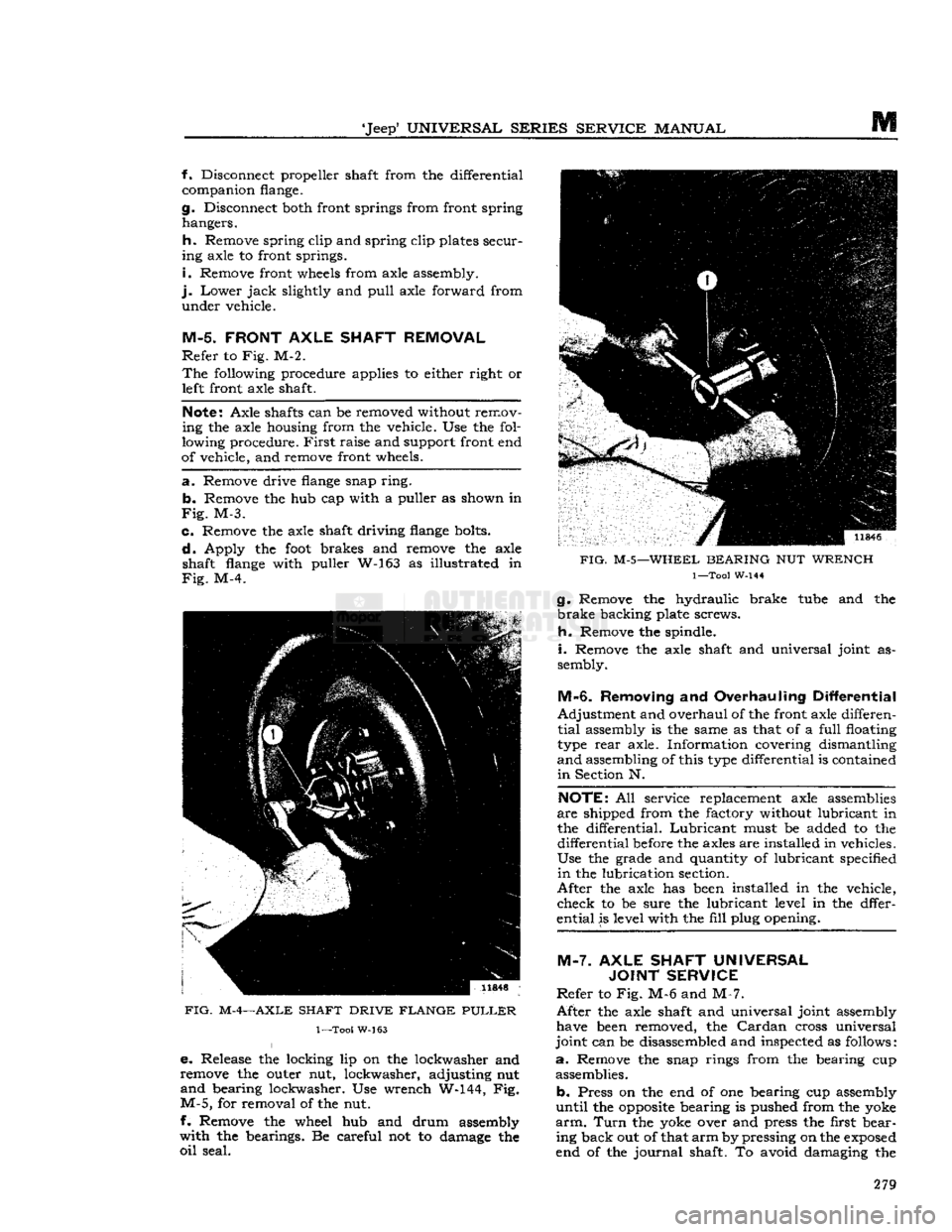
Apply the
foot
brakes and remove the axle shaft
flange
with puller W-163 as illustrated in
Fig.
M-4.
FIG.
M-4—AXLE
SHAFT
DRIVE
FLANGE
PULLER
1—Too!
W-163
e.
Release the locking lip on the lockwasher and
remove the outer nut, lockwasher, adjusting nut
and
bearing lockwasher. Use wrench W-144, Fig.
M-5,
for removal of the nut.
f- Remove the wheel hub and drum assembly
with
the bearings. Be careful not to damage the
oil
seal.
FIG.
M-5—WHEEL
BEARING
NUT
WRENCH
1—Tool
W-144
g.
Remove the hydraulic brake
tube
and the
brake
backing plate screws.
h.
Remove the spindle.
i.
Remove the axle shaft and universal joint as
sembly.
M-6.
Removing
and
Overhauling Differential
Adjustment
and overhaul of the front axle differen
tial
assembly is the same as that of a
full
floating
type
rear
axle. Information covering dismantling
and
assembling of this
type
differential is contained
in
Section N.
NOTE:
All service replacement axle assemblies
are
shipped from the factory without lubricant in
the differential.
Lubricant
must be added to the
differential
before
the axles are installed in vehicles.
Use
the grade and quantity of lubricant specified
in
the lubrication section.
After
the axle has
been
installed in the vehicle,
check
to be sure the lubricant level in the dffer-
ential
is level with the
fill
plug opening.
M-7.
AXLE SHAFT UNIVERSAL JOINT SERVICE
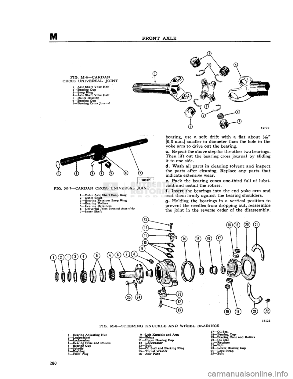
Refer
to Fig. M-6 and M-7.
After
the axle shaft and universal joint assembly have
been
removed, the
Cardan
cross universal
joint
can be disassembled and inspected as follows:
a.
Remove the snap rings from the bearing cup assemblies.
b.
Press on the end of one bearing cup assembly
until
the
opposite
bearing is pushed from the yoke
arm.
Turn
the yoke over and press the first bear ing back out of that
arm
by pressing on the
exposed
end of the
journal
shaft. To avoid damaging the 279
Page 280 of 376
M
FRONT
AXLE
FIG.
M-6—CARDAN
CROSS
UNIVERSAL
JOINT
1—Axle
Shaft Yoke
Half
2-—Bearing Cup
3— Snap Ring 4— Axle Shaft Yoke
Half
5— Roller Bearing
6— Bearing Cup 7— Bearing Cross Journal
10527
FIG.
M-7—CARDAN
CROSS
UNIVERSAL
JOINT
1— Outer Axle Shaft Snap Ring
2— Outer Shaft
3— Bearing Retainer Snap Ring
4— Bearing Rollers 5— Bearing Retainers
6— Universal Joint Journal Assembly 7—
Inner
Shaft bearing, use a
soft
drift with a
flat
about
[0,8 mm.] smaller in
diameter
than the
hole
in the
yoke
arm to drive out the bearing.
c.
Repeat
the
above
step
for the
other
two
bearings.
Then
lift
out the
bearing
cross
journal by
sliding
it to one
side.
d. Wash all parts in
cleaning
solvent
and
inspect
the parts
after
cleaning.
Replace any parts
that
indicate
extensive
wear.
e. Pack the
bearing
cones
one-third
full of lubri
cant
and install the rollers.
f. Insert the
bearings
into
the end
yoke
arm and
seat
them
firmly
against
the
bearing
shoulders.
g.
Holding
the
bearings
in a vertical
position
to
prevent
the
needles
from
dropping
out,
reassemble
the joint in the
reverse
order of the
disassembly.
FIG.
M-8—STEERING KNUCKLE AND WHEEL BEARINGS
1— Bearing Adjusting Nut
2— Lockwasher
3— Lockwasher
4— Bearing Cone and Rollers 5— Bearing Cup
6— Spindle 7— Bushing
8—
Filler
Plug 9—Left Knuckle and Arm
10— Shims
11— Upper Bearing Cap 12— Lockwasher
13—Bolt
14—
Oil
Seal and Backing Ring
15—
Thrust
Washer
16— Axle Pilot 17—
Oil
Seal
18— Bearing Cup
19— Bearing Cone and Rollers
20—
Oil
Seal
21— Retainer
22— Bolt
23—
Lower
Bearing Cap
24—
Lock
Strap
25— Bolt 280