LAND ROVER FRELANDER 2 2006 Repair Manual
Manufacturer: LAND ROVER, Model Year: 2006, Model line: FRELANDER 2, Model: LAND ROVER FRELANDER 2 2006Pages: 3229, PDF Size: 78.5 MB
Page 1021 of 3229
Publi s hed: 11-May-2011
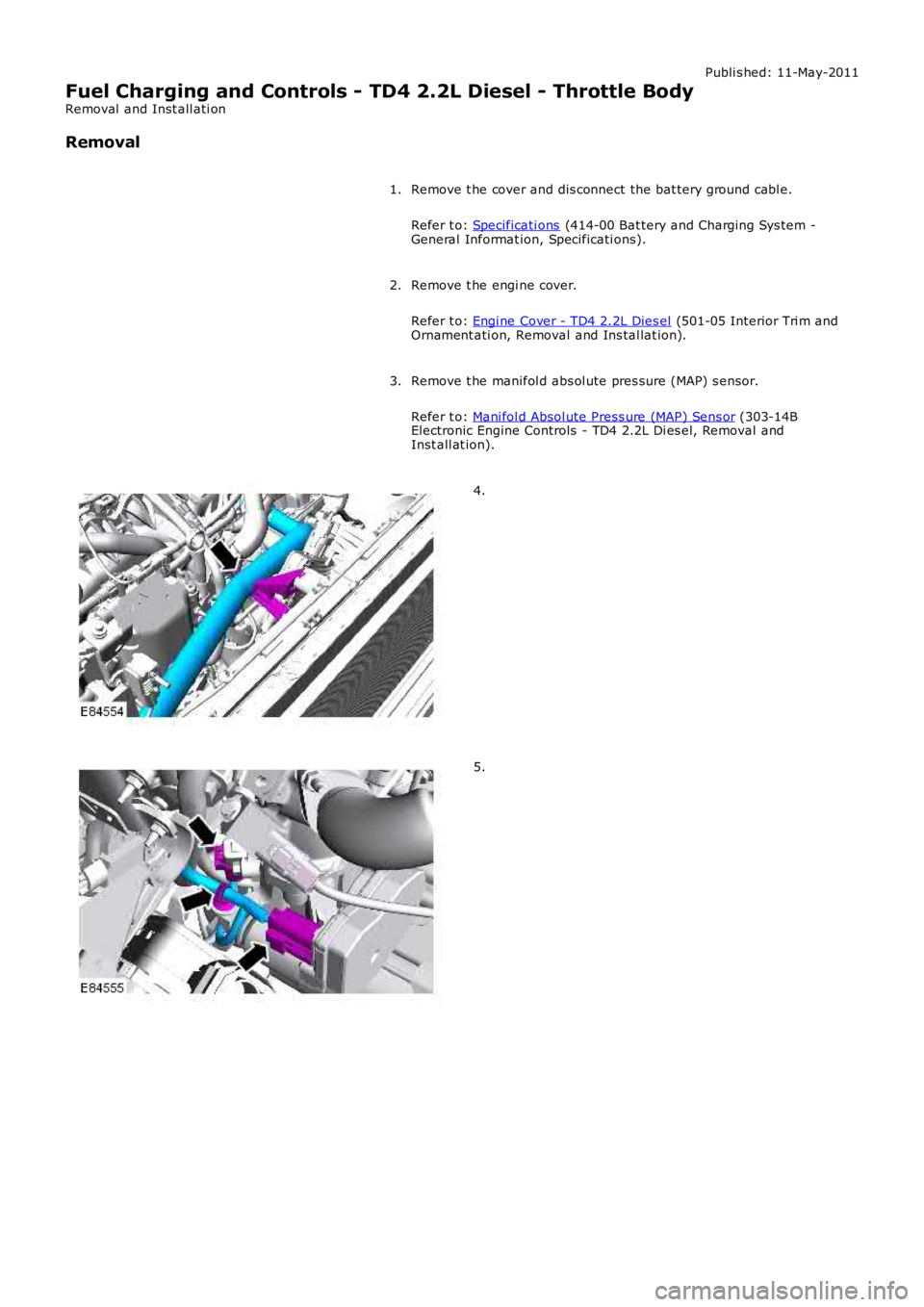
Fuel Charging and Controls - TD4 2.2L Diesel - Throttle Body
Removal and Inst all ati on
Removal
Remove t he cover and dis connect the bat tery ground cabl e.
Refer t o: Specificati ons (414-00 Bat tery and Charging Sys tem -General Informat ion, Specificati ons).
1.
Remove t he engi ne cover.
Refer t o: Engi ne Cover - TD4 2.2L Dies el (501-05 Interior Tri m andOrnament ati on, Removal and Ins tal lat ion).
2.
Remove t he manifol d abs ol ute pres sure (MAP) s ens or.
Refer t o: Mani fol d Absol ute Press ure (MAP) Sens or (303-14BElectronic Engine Controls - TD4 2.2L Di es el, Removal andInst all at ion).
3.
4.
5.
Page 1022 of 3229
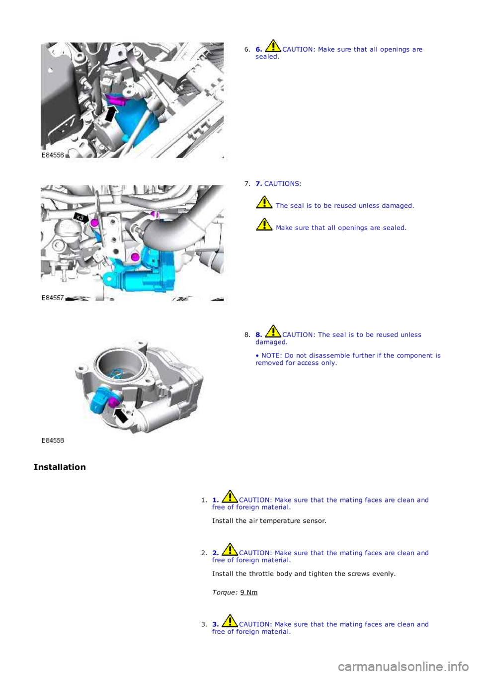
6. CAUTION: Make s ure that all openi ngs are
s ealed.
6. 7.
CAUTIONS: The s eal is t o be reused unl es s damaged.
Make s ure that all openings are sealed.
7. 8. CAUTION: The s eal i s t o be reus ed unles s
damaged.
• NOTE: Do not di sas s emble furt her i f the component is
removed for acces s onl y.
8.
Installation 1. CAUTION: Make s ure that the mati ng faces are cl ean and
free of foreign mat eri al.
Inst all t he air t emperature s ens or.
1.
2. CAUTION: Make s ure that the mati ng faces are cl ean and
free of foreign mat eri al.
Inst all t he thrott le body and t ighten the s crews evenly.
T orque: 9 Nm 2.
3. CAUTION: Make s ure that the mati ng faces are cl ean and
free of foreign mat eri al.
3.
Page 1023 of 3229
Connect t he int ake hos e and s ecure wi th the cl ip.
Connect t he electrical connect ors .4.
Secure t he cool ant t op hos e.5.
Inst all t he MAP s ensor.
Refer t o: Mani fol d Absol ute Press ure (MAP) Sens or (303-14BElectronic Engine Controls - TD4 2.2L Di es el, Removal andInst all at ion).
6.
Inst all t he engi ne cover.
Refer t o: Engi ne Cover - TD4 2.2L Dies el (501-05 Interior Tri m andOrnament ati on, Removal and Ins tal lat ion).
7.
Connect t he batt ery ground cable and ins tall t he cover.
Refer t o: Specificati ons (414-00 Bat tery and Charging Sys tem -General Informat ion, Specificati ons).
8.
Page 1024 of 3229
Publi s hed: 11-May-2011
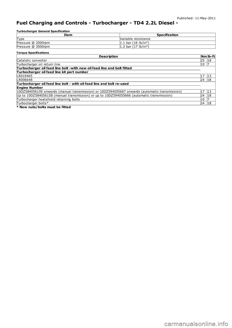
Fuel Charging and Controls - Turbocharger - TD4 2.2L Diesel -
Turbocharger General SpecificationItemSpecification
TypeVariable res is t ance
Pres s ure @ 2000rpm1.1 bar (16 lb/in²)Pres s ure @ 3000rpm1.2 bar (17 lb/in²)
Torque SpecificationsDescriptionNmlb-ft
Catal yt ic convert er2518
Turbocharger oi l ret urn l ine107T urbocharger oil feed line bolt -w ith new oil feed line and bolt fitted
T urbocharger oil feed line kit part number
LR0194651713LR0066482418
T urbocharger oil feed line bolt - with oil feed line and bolt re-used
Engine Number10DZ584056159 onwards (manual t ransmis s ion) or 10DZ594055667 onwards (automat ic t rans mis s ion)1713
Up t o 10DZ584056158 (manual t rans mis s ion) or up to 10DZ594055666 (automat ic t rans miss ion)2418
Turbocharger heat shi el d ret aini ng bol ts107Turbocharger bol ts *2418
* New nuts/bolts must be fitted
Page 1025 of 3229
Publi s hed: 11-May-2011
Fuel Charging and Controls - Turbocharger - TD4 2.2L Diesel - Turbocharger
Des cript ion and Operat ion
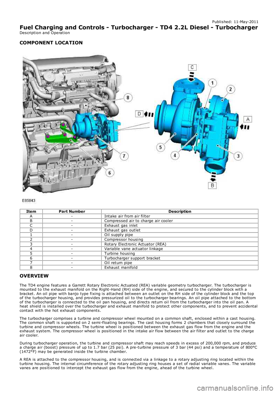
COMPONENT LOCATION
ItemPart NumberDescription
A-Int ake ai r from ai r fi lt erB-Compres sed ai r to charge air cool er
C-Exhaus t gas inlet
D-Exhaus t gas out let1-Oil s uppl y pipe
2-Compres sor housi ng
3-Rot ary El ect roni c Act uator (REA)4-Variable vane act uat or li nkage
5-Turbine hous ing
6-Turbocharger s upport bracket7-Oil ret urn pipe
8-Exhaus t manifol d
OVERVIEW
The TD4 engine feat ures a Garret t Rotary Electroni c Actuated (REA) variabl e geomet ry turbocharger. The t urbocharger i smounted t o t he exhaus t manifold on the Ri ght -Hand (RH) s ide of t he engine, and secured t o t he cyl inder block wit h abracket . An oil pi pe wit h banjo type fixing i s att ached bet ween an outl et on the RH s ide of t he cyl inder bl ock and the t opof the turbocharger hous ing, and provides pres s uri zed oi l to the t urbocharger beari ngs. An oi l pipe at tached to the bot tomof the turbocharger is connect ed to the oi l pan hous ing, and direct s ret urn oi l from t he t urbocharger i nt o t he oil pan. Aheat shi el d i s ins tal led over the t urbocharger and exhaust mani fold to protect other component s, and t o prevent acci dent alcont act wit h the hot exhaus t component s .
The t urbocharger compri ses a turbi ne and compres sor wheel mounted on a common s haft, enclos ed wit hin a cas t hous ing.The common s haft i s s upport ed on 2 semi -float ing beari ngs . The cast hous ing forms 2 chambers that clos ely s urround thet urbine and compres s or wheel s. The t urbine wheel i s pos i ti oned bet ween the exhaust gas flow from t he engine and t heexhaus t s ys t em. The compress or wheel is pos it ioned in the i ntake air flow bet ween t he air filt er and out let t o t he chargeair cooler.
Duri ng turbocharger operati on, t he t urbine and compres s or s haft may reach s peeds in exces s of 200,000 rpm, and producea charge ai r (boost ) pres s ure of up t o 1.7 bar (25 ps i). A pre-t urbine press ure of 3 bar (44 ps i) and a temperat ure of 800°C(1472°F) may be generated i nsi de t he turbi ne chamber.
A REA is at tached to the compres s or hous ing, and is connect ed via a li nkage t o a rotary adjus ti ng ri ng located wit hi n t het urbine hous ing. The internal circumference of t he rot ary adjus t ing ring hous es a s et of radial variable vanes . The variablevanes are pos it ioned to int ercept t he exhaus t gas fl ow from the engine, ahead of the t urbi ne wheel .
Page 1026 of 3229
The REA i s direct ly controlled by the Engine Cont rol Modul e (ECM). The ECM cons tantly cont rol s t he pos i ti on of the actuat orus ing i nput i nformat ion from vari ous engine and vehicle mounted s ensors . A feed back s ens or wi thin the REA cont inuous lyinforms the ECM of t he actuat or pos it ion during t urbocharger operat ion. In the event that t he variable vanes fail to reacht he request ed posi ti on, a Diagnost ic Troubl e Code (DTC) i s s tored in the ECM memory.
PRINCIPLES OF OPERATION
The t urbocharger us es the energy of t he exhaus t gas fl ow from the engi ne to provide compres s ed (charged) air t o theint ake air s ys t em. The variable geomet ry vanes make s ure the turbocharger produces the required level of intake ai r boos tpres s ure for the current engi ne operati ng condit ions .
The t urbocharged engine provi des the foll owing advant ages over a convent ional nat urall y as pi rat ed engi ne:
Great er vol umet ric efficiencyImproved engi ne power and torqueReduced fuel consumpt ionReduced emi ss i onsRe-us e of exhaus t gas energyUn-affected by al ti tudeLimi ted periods of over-boos t for immediate engi ne demands .
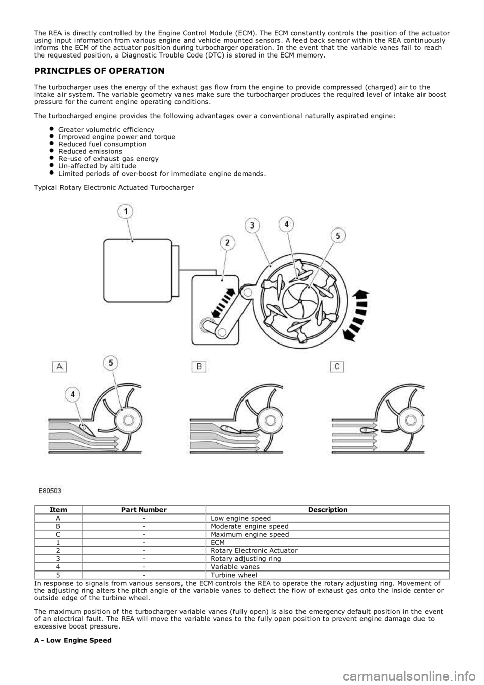
Typi cal Rot ary Electronic Actuat ed Turbocharger
ItemPart NumberDescription
A-Low engine s peedB-Moderate engi ne s peed
C-Maximum engi ne s peed
1-ECM2-Rotary Electroni c Actuator
3-Rotary adjus ti ng ri ng
4-Vari abl e vanes5-Turbine wheel
In res pons e to s i gnal s from vari ous s ens ors , t he ECM cont rol s t he REA t o operate the rotary adjus ti ng ri ng. Movement oft he adjust ing ri ng alt ers t he pit ch angl e of the variable vanes t o deflect t he fl ow of exhaus t gas ont o t he i ns i de cent er orouts ide edge of t he t urbine wheel.
The maximum posi ti on of the turbocharger variable vanes (full y open) is als o the emergency default pos it ion i n t he eventof an electrical fault . The REA wil l move t he variable vanes t o t he ful ly open posi ti on t o prevent engi ne damage due toexces s ive boost press ure.
A - Low Engine Speed
Page 1027 of 3229
At low engi ne s peed t he volume of exhaust gas l eavi ng the engine is l ow. The vanes are moved toward the cl osed pos it iont o direct t he exhaus t gas fl ow t o t he out s ide edge of t he turbine wheel. The clos ed posi ti on of the vanes creates ares t ri ct ion t o t he gas fl ow and i ncreas es t he gas vel oci ty to the t urbine wheel . The turbi ne wheel s peed is increas ed,cons equent ly producing more charge ai r (boos t pres sure) from t he compres sor.
B - Moderate Engine Speed
As engine s peed and exhaus t gas vol ume increas e, the vanes are moved to the open posit ion t o direct t he exhaus t gasfl ow t oward t he center of the turbi ne wheel . The vanes do not rest ri ct the exhaus t gas flow and therefore exhaus t gasveloci ty is dependant on engine s peed. The t urbi ne wheel s peed is maintai ned due to the i ncreas ed velocit y of t he gas esleaving t he engine and being di rected t oward the center area of t he t urbine wheel .
C - Maximum Engine Speed
At maximum engine s peed the volume of exhaus t gas leavi ng t he engi ne is hi gh. The vanes are moved toward the full yopen pos i ti on and do not affect t he gas vel oci ty. The exhaus t gas fl ow contacts t he center area of t he t urbine wheel tomaint ain t he t urbine wheel s peed and boos t pres s ure from the compress or.
Over-Boost Pressure
Duri ng periods of medi um t o hard accelerat ion, the turbocharger is requi red t o produce a l imit ed period of over-boos tpres s ure from the compress or to meet the current engi ne fueli ng requirement. The ECM wil l reques t and all ow t he REA t omove t he variable vanes t oward t he clos ed posi ti on t o increas e t he vel oci ty of t he already high-s peed turbine wheel. Theover-boos t condit ion is all owed by t he ECM for t he l imi ted period.
Barometric Pressure Sensor
At high al ti tude t he t urbocharger wi ll functi on normal ly, but due t o t he l ower ambi ent ai r pres sure t he turbi ne andcompres sor may tend t o over-speed. A baromet ri c pres sure s ensor i s located i n t he ECM t o prevent over-boost andposs i bl e engine damage occurri ng under t hes e condit ions. The ECM opens t he vari abl e vanes earlier duri ng t he openi ngphas e to s uit the al ti tude of t he vehi cl e.
T urbocharger Lubrication
The rapi d accelerat ion and decelerat ion demands of t he turbocharger rel y on a s t eady flow of cl ean oil. The oi l suppli ed byt he engi ne lubri cat ion s ys tem provides l ubricati on to the t urbocharger shaft and bearings, whi le al so act ing as a cool antfor t he t urbocharger cent er hous i ng.
To mai nt ain the l ife expect ancy of t he turbocharger, t he engine oil mus t be replenished at regular s ervice i nt ervals wit ht he recommended qual it y and quant it y of oil . The oi l mus t have a free-fl ow t hrough the turbocharger and an unres trict edret urn to t he engine oi l pan.
Page 1028 of 3229
Publi s hed: 11-May-2011
Fuel Charging and Controls - Turbocharger - TD4 2.2L Diesel - Turbocharger
Actuator Rod
Removal and Inst all ati on
Removal
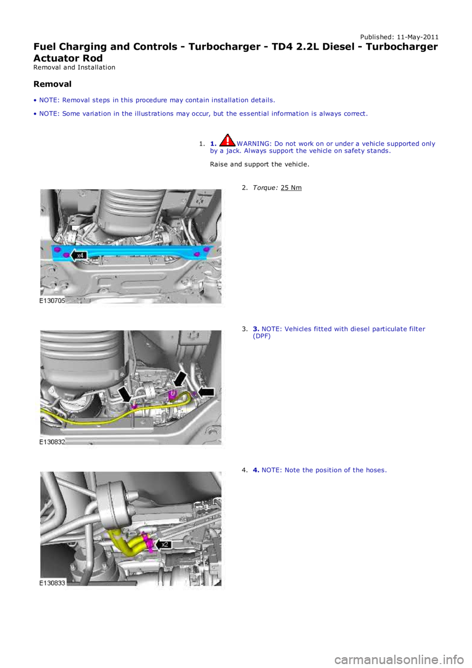
• NOTE: Removal s t eps in t his procedure may cont ain i nst all ati on det ail s.
• NOTE: Some vari ati on in the i ll us t rat ions may occur, but the es s ent ial informat ion i s always correct .
1. W ARNING: Do not work on or under a vehi cle s upported onl y
by a jack. Al ways support t he vehi cl e on s afet y s tands .
Rais e and s upport t he vehi cl e.
1. T orque:
25 Nm 2.
3.
NOTE: Vehi cl es fi tt ed wi th di esel part iculat e filt er
(DPF)
3. 4.
NOTE: Note the pos it ion of t he hoses .
4.
Page 1029 of 3229
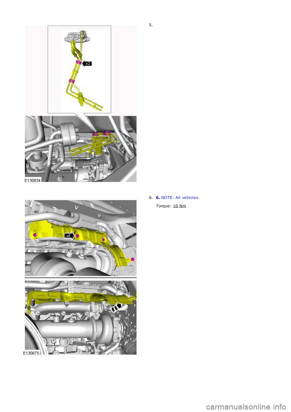
5.
6.
NOTE: All vehi cles .
T orque: 10 Nm 6.
Page 1030 of 3229
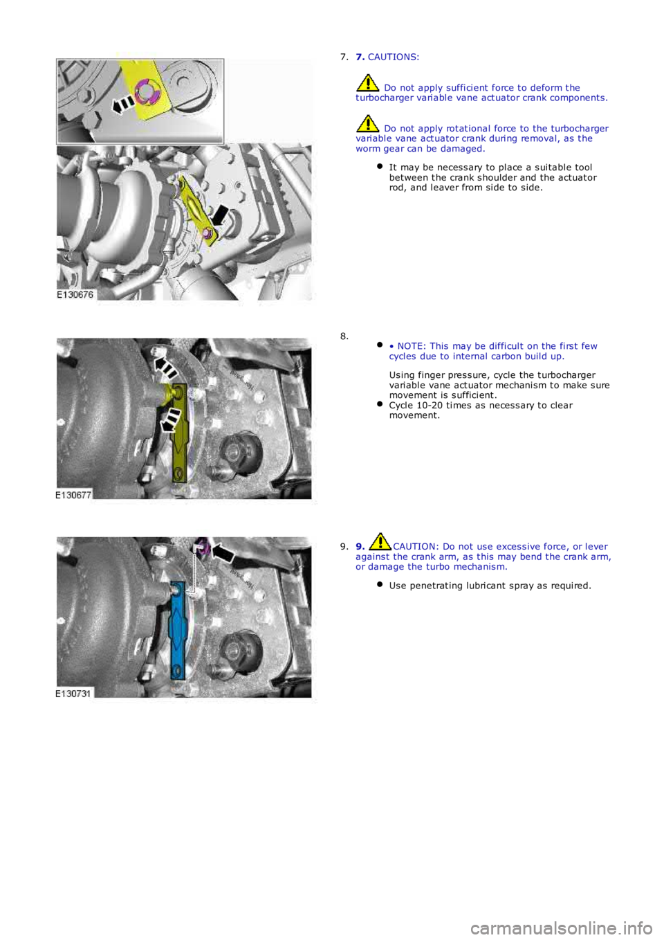
7. CAUTIONS:
Do not apply suffi ci ent force t o deform t het urbocharger vari abl e vane act uator crank component s.
Do not apply rot at ional force to the t urbochargervari abl e vane act uator crank duri ng removal, as t heworm gear can be damaged.
It may be neces s ary to pl ace a s ui tabl e toolbetween t he crank s houlder and the actuat orrod, and l eaver from si de to s ide.
7.
• NOTE: This may be diffi cul t on the fi rs t fewcycl es due to internal carbon buil d up.
Us ing finger pres s ure, cycle the t urbochargervari abl e vane act uator mechani sm t o make s uremovement is s uffici ent .Cycl e 10-20 ti mes as neces s ary t o clearmovement.
8.
9. CAUTION: Do not us e exces s ive force, or l everagains t the crank arm, as t his may bend t he crank arm,or damage the turbo mechanis m.
Us e penetrat ing lubri cant s pray as requi red.
9.