LAND ROVER FRELANDER 2 2006 Repair Manual
Manufacturer: LAND ROVER, Model Year: 2006, Model line: FRELANDER 2, Model: LAND ROVER FRELANDER 2 2006Pages: 3229, PDF Size: 78.5 MB
Page 991 of 3229
Publi s hed: 11-May-2011
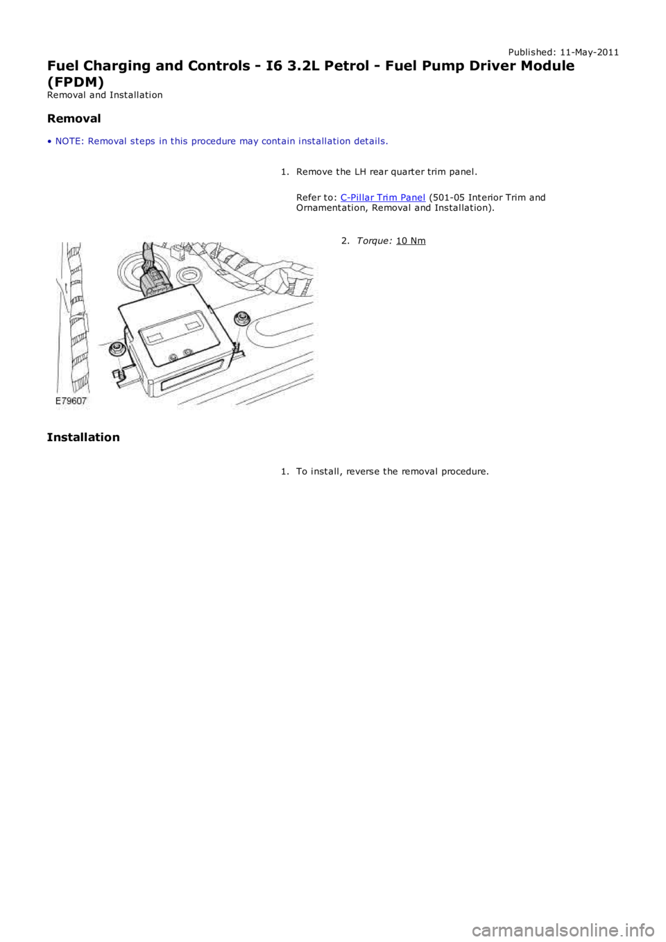
Fuel Charging and Controls - I6 3.2L Petrol - Fuel Pump Driver Module
(FPDM)
Removal and Inst all ati on
Removal
• NOTE: Removal s t eps in t his procedure may cont ain i nst all ati on det ail s.
Remove t he LH rear quart er trim panel .
Refer t o: C-Pil lar Tri m Panel (501-05 Int erior Trim and
Ornament ati on, Removal and Ins tal lat ion).
1. T orque:
10 Nm 2.
Installation To i nst all , revers e t he removal procedure.
1.
Page 992 of 3229
Publi s hed: 11-May-2011
Fuel Charging and Controls - TD4 2.2L Diesel -
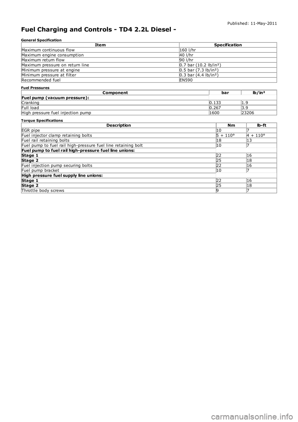
General SpecificationItemSpecification
Maximum cont inuous fl ow160 l /hr
Maximum engine cons umpt ion40 l /hrMaximum ret urn fl ow90 l /hr
Maximum pres s ure on return l ine0.7 bar (10.2 lb/in²)
Mi ni mum pres sure at engi ne0.5 bar (7.3 lb/in²)Mi ni mum pres sure at fi lt er0.3 bar (4.4 lb/in²)
Recommended fuelEN590
Fuel Pressures
Componentbarlb/in²
Fuel pump (vacuum pressure):Cranking0.1331.9
Full load0.2673.9
Hi gh pres sure fuel i nject ion pump160023206
Torque SpecificationsDescriptionNmlb-ft
EGR pi pe107
Fuel i njector clamp ret ai ning bolt s5 + 110°4 + 110°Fuel rail ret aini ng bol ts1813
Fuel pump to fuel rail hi gh-pres s ure fuel l ine retaini ng bolt107
Fuel pump to fuel rail high-pressure fuel line unions:Stage 12216
Stage 22518
Fuel i njecti on pump s ecuring bolt s2216Fuel pump bracket107
High pressure fuel supply line unions:
Stage 12216Stage 22518
Throt tl e body s crews97
Page 993 of 3229
Publi s hed: 11-May-2011
Fuel Charging and Controls - TD4 2.2L Diesel - Fuel Charging and Controls
Des cript ion and Operat ion
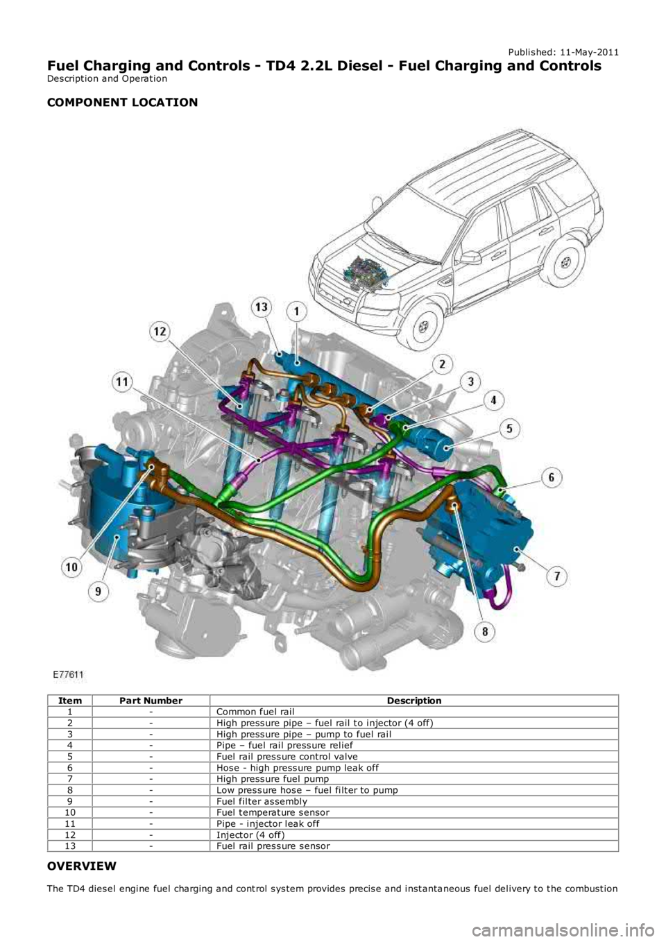
COMPONENT LOCATION
ItemPart NumberDescription1-Common fuel rail
2-High press ure pipe – fuel rail t o i njector (4 off)
3-High press ure pipe – pump to fuel rai l4-Pipe – fuel rai l press ure rel ief
5-Fuel rail pres s ure control valve
6-Hos e - high press ure pump leak off7-High press ure fuel pump
8-Low pres s ure hos e – fuel fi lt er t o pump
9-Fuel fil ter as sembl y10-Fuel t emperat ure s ensor
11-Pipe - i njector l eak off
12-Inject or (4 off)13-Fuel rail pres s ure s ensor
OVERVIEW
The TD4 dies el engi ne fuel charging and cont rol s ys tem provides precis e and i nst antaneous fuel del ivery t o t he combust ion
Page 994 of 3229
chambers. Thi s provides opti mum performance, all owing t he engi ne t o be extremely respons ive t o dri ver demands for al ldri vi ng condi ti ons . The fuel s yst em features a Bos ch Generat ion 3 common rai l injection s yst em that is moni tored andcont rol led by an engine control modul e (ECM), t o precis ely cont rol the fueli ng st rategy.
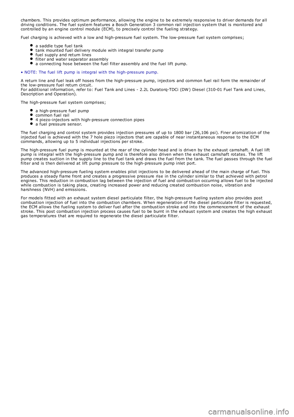
Fuel charging is achieved wit h a l ow and hi gh-pres sure fuel s yst em. The l ow-pres s ure fuel s ys tem compris es ;
a s addle t ype fuel tankt ank mount ed fuel deli very module wi th int egral trans fer pumpfuel s uppl y and ret urn linesfi lt er and water s eparator as sembl ya connect ing hos e between t he fuel filt er ass embly and the fuel lift pump.
• NOTE: The fuel l ift pump is i ntegral wi th the hi gh-pres s ure pump.
A return li ne and fuel leak off hos es from the hi gh-pres s ure pump, i nject ors and common fuel rai l form t he remai nder oft he low-pres sure fuel ret urn ci rcuit .For addit ional informat ion, refer t o: Fuel Tank and Lines - 2.2L Duratorq-TDCi (DW ) Dies el (310-01 Fuel Tank and Li nes ,Des cript ion and Operat ion).
The high-press ure fuel s ys t em compri s es ;
a hi gh-pres sure fuel pumpcommon fuel rail4 pi ezo-injectors wit h hi gh-pres s ure connecti on pipesa fuel press ure sens or.
The fuel charging and control s ys tem provides i nject ion press ures of up to 1800 bar (26,106 psi ). Fi ner at omizati on of theinject ed fuel is achieved wi th the 7 hol e piezo i njectors that are capable of near ins tant aneous res ponse to the ECMcommands , all owing up to 5 individual inject ions per st roke.
The high-press ure fuel pump i s mounted at t he rear of t he cyl inder head and i s dri ven by the exhaust cams haft . A fuel l iftpump i s int egral wit h t he high-pres s ure pump and is therefore al so driven when t he exhaus t cams haft rot ates . The li ftpump creat es suct ion i n the supply line to t he fuel t ank and draws t he fuel from the t ank. The fuel pas s es through the fuelfi lt er and is t hen delivered at lift pump pres s ure to the hi gh-pres sure pump i nlet port .
The advanced high-press ure fueli ng s ys t em enables pil ot inject ions to be delivered ahead of t he main charge of fuel. Thisproduces a s teady fl ame front and creates a progres s ive pres s ure ris e in t he cyl inder s imi lar to that achi eved wit h petrolengi nes. This reduct ion i n combust ion lag between t he i nject ion of fuel and combus tion occurring al lows fuel t o be i njectedwhil e combus t ion i s t aki ng place, creat ing i ncreas ed power and reducing creat ed combus t ion nois e, vibrat ion andhars hnes s (NVH) and emis s ions .
For model s fi tt ed wi th an exhaus t sys t em dies el parti cul ate fil ter, the hi gh-pres s ure fueling sys tem als o provi des pos tcombus t ion i njecti on of fuel into the combus ti on chambers. W hen regenerati on of the di esel part iculat e fi lt er is reques t ed,t he ECM all ows the fueli ng s ys t em t o deli ver fuel after t he combus t ion s troke and int o t he commencement of the exhausts troke. This pos t combus t ion i njecti on proces s caus es fuel to be burnt in the exhaust s ys tem and creates t he high exhaus tgas temperatures that are required to regenerate t he dies el part icul ate fi lt er.
Page 995 of 3229
Publi s hed: 11-May-2011
Fuel Charging and Controls - TD4 2.2L Diesel - Fuel Charging and Controls
Des cript ion and Operat ion
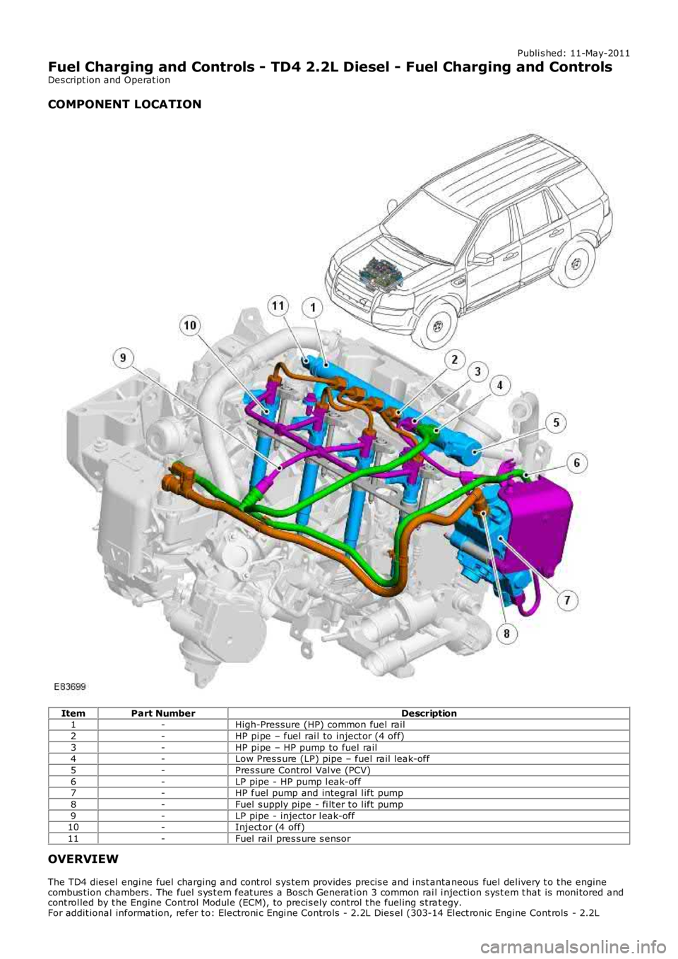
COMPONENT LOCATION
ItemPart NumberDescription1-High-Pres sure (HP) common fuel rail
2-HP pi pe – fuel rai l to inject or (4 off)
3-HP pi pe – HP pump to fuel rail4-Low Pres s ure (LP) pipe – fuel rail l eak-off
5-Pres s ure Control Val ve (PCV)
6-LP pipe - HP pump l eak-off7-HP fuel pump and integral l ift pump
8-Fuel s upply pipe - fi lt er t o l ift pump
9-LP pipe - injector l eak-off10-Inject or (4 off)
11-Fuel rail pres s ure s ensor
OVERVIEW
The TD4 dies el engi ne fuel charging and cont rol s ys tem provides precis e and i nst antaneous fuel del ivery t o t he enginecombus t ion chambers . The fuel s ys t em feat ures a Bosch Generat ion 3 common rai l i njecti on s ys t em t hat is moni tored andcont rol led by t he Engine Control Modul e (ECM), to precis ely control t he fuel ing s t rat egy.For addit ional informat ion, refer t o: Electroni c Engi ne Controls - 2.2L Dies el (303-14 El ect ronic Engine Cont rols - 2.2L
Page 996 of 3229
Dies el, Des cript ion and Operat ion).
Fuel i njecti on pres sure is generat ed i ndependent ly of engine s peed and fuel inject ion events . The HP fuel s ys tem iscont rol lable t o t he opti mum level for smoot h operat ion, and is capabl e of devel opi ng an i nject ion press ure up t o 1,600 bar(23,206 psi ). The fuel i njecti on ti ming and vol ume are cal cul at ed by t he ECM t hat als o energizes t he appropriat e piezo-act uated i njector.
The fuel s yst em features a pre-inject ion (pilot ) phas e t o reduce combus ti on noi s e and mechani cal load. On vehiclesins t al led wi th a Di es el Part iculate Fi lt er (DPF), t he fuel s ys tem als o provides a pos t -i nject ion phas e t hat is requi red forregenerat ing t he DPF.For addit ional informat ion, refer t o: Exhaus t Sys t em (309-00B Exhaus t Syst em - TD4 2.2L Di es el, Des cri pt ion andOperat ion).
This t ype of fuel sys t em all ows t he TD4 engi ne t o achi eve excellent l evels of performance and engine res pons e, whilebeing able to meet current and fut ure exhaus t emi s si on legis l at ion.
Fuel charging is achieved wit h a LP and HP fuel s ys t em. The LP fuel s yst em compris es:
Saddl e t ype fuel tankTank mount ed fuel deli very module and integral t rans fer pumpFuel s upply and return li nesFil ter and water s eparator as s embly.For addit ional informat ion, refer t o: Fuel Tank and Lines (310-01B Fuel Tank and Lines - TD4 2.2L Dies el ,Des cript ion and Operat ion).
The HP fuel s ys tem compris es :
HP fuel pump wit h int egral mounted l ift pump and Volume Cont rol Valve (VCV)Common fuel rail wi th integral PCV and press ure s ens or4 pi ezo-injectorsHP connect ing pipesFuel l eak-off pipes .
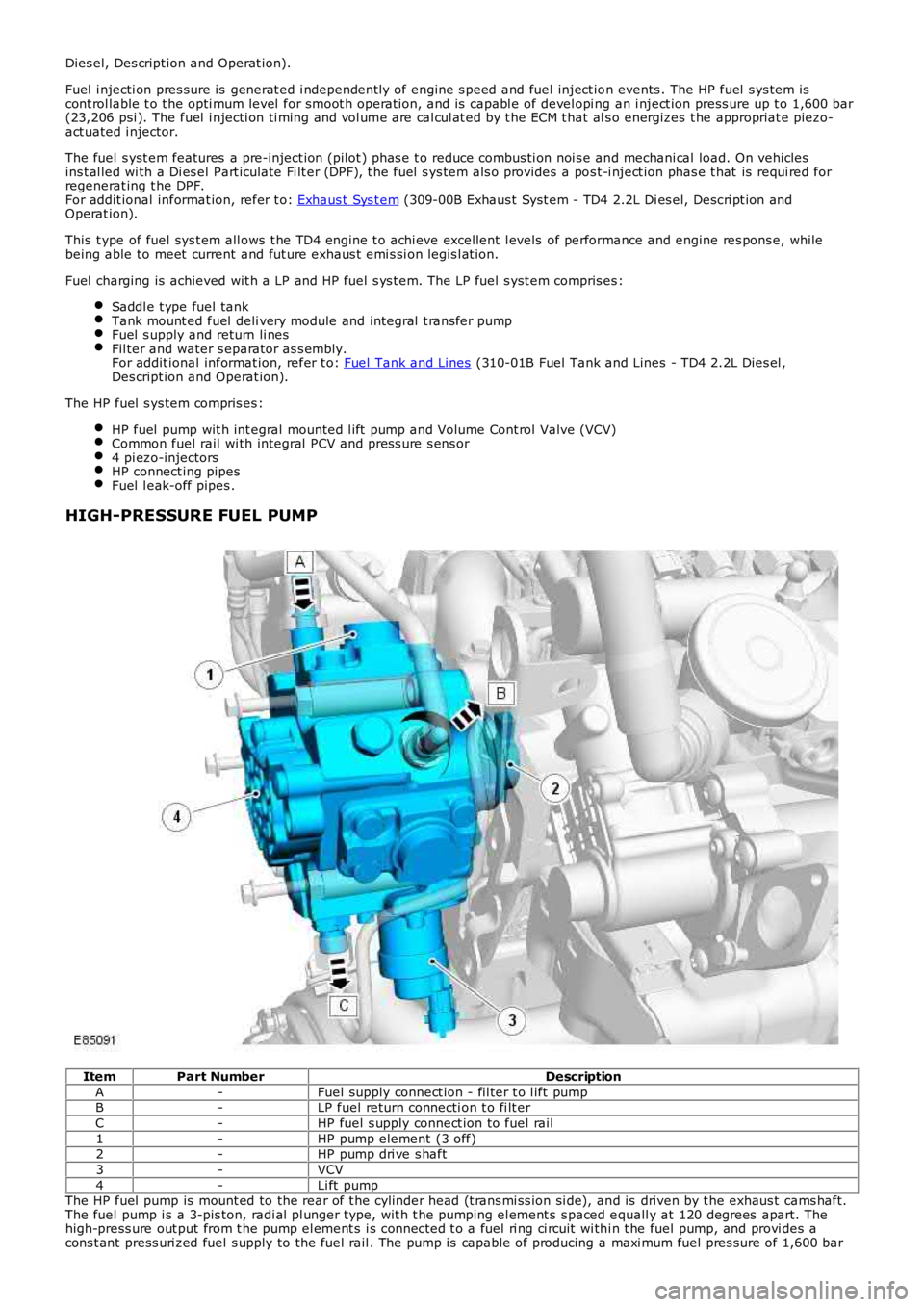
HIGH-PRESSURE FUEL PUMP
ItemPart NumberDescription
A-Fuel supply connect ion - fil ter t o l ift pumpB-LP fuel return connecti on t o fi lt er
C-HP fuel s upply connect ion to fuel rail
1-HP pump element (3 off)2-HP pump dri ve s haft
3-VCV
4-Li ft pumpThe HP fuel pump is mount ed to the rear of t he cylinder head (t rans mi ss ion si de), and is driven by t he exhaus t cams haft.The fuel pump i s a 3-pis ton, radi al pl unger type, wit h t he pumping el ement s s paced equall y at 120 degrees apart. Thehigh-press ure out put from t he pump el ement s i s connected t o a fuel ri ng ci rcuit wi thi n t he fuel pump, and provi des acons t ant press uri zed fuel s upply to the fuel rail . The pump is capable of producing a maxi mum fuel pres sure of 1,600 bar
Page 997 of 3229
(23,206 psi ).
The fuel s yst em HP pump compri ses t he fol lowi ng components :
3 HP pumpi ng element sInt egral li ft pumpVolume Cont rol Valve (VCV).
The HP pump and integral l ift pump mus t not be s eparat ed. The HP pump i s not ti med to t he engi ne.
A controlled amount of fuel i s all owed to leak-off t hrough t he HP pump, and ret urned t hrough a l eak-off pipe t o t he fuelfi lt er. The l eak-off fuel provides cooling and lubri cat ion for the HP pump int ernal components .
Lift Pump
A fuel l ift pump i s mounted t o t he rear of t he fuel pump, and forms an int egral ass embly wit h t he HP pump. The fuel li ftpump i s a gear type pump and connect ed to the fuel fi lt er s upply l ine. The li ft pump creat es a vacuum (negati ve pres s ure)in the s upply l ine t o t he fuel t ank, and draws the fuel from t he tank. The fuel passes t hrough the fuel fi lt er and i s t hendelivered at lift pump pres s ure to the HP pump inl et port.
The li ft pump normal operati ng, negati ve pres sure values are shown for the foll owing engine condi ti ons:
Engine ConditionLift Pump Negative PressureCranking-133 ± 7 mbar (-10 ± 0.5 cmHg)
Full load-267 ± 133 mbar (-20 ± 10 cmHg)
Volume Control Valve (VCV)
The VCV i s mounted on the HP pump, and l ocat ed in the feed port between t he HP pump elements and the fuel l ift pump.The VCV i s a vari abl e pos it ion s olenoid-operat ed valve t hat i s cont rol led by t he ECM wit h a 12V Puls e W idt h Modulat ed(PW M) s ignal. The VCV controls t he quant it y of fuel deli vered by the lift pump t o t he HP pump el ements .
W hen t he HP fuel pump rot ates , pres sure is created when t he VCV i s open and the fuel rail mount ed PCV is cl osed. TheVCV and PCV are vari abl e posi ti on valves, and us ed by t he ECM t o cont rol fuel deli very and fuel s ys tem pres sure.
Duri ng the fuel heat ing period when t he s uppl y fuel t emperature is les s than 40°C (104°F), t he ECM will fully open theVCV. Fuel volume and press ure is t hen cont rol led di rectl y by the PCV under t he cont rol of the ECM.
The VCV i s normal ly open when t he s ol enoi d i s not energi zed by the ECM. The resi s tance val ue of the VCV s ol enoi d coil is2.8 ohms at 20°C (68°F).For addit ional informat ion, refer t o: Electroni c Engi ne Controls - 2.2L Dies el (303-14 El ect ronic Engine Cont rols - 2.2LDies el, Des cript ion and Operat ion).
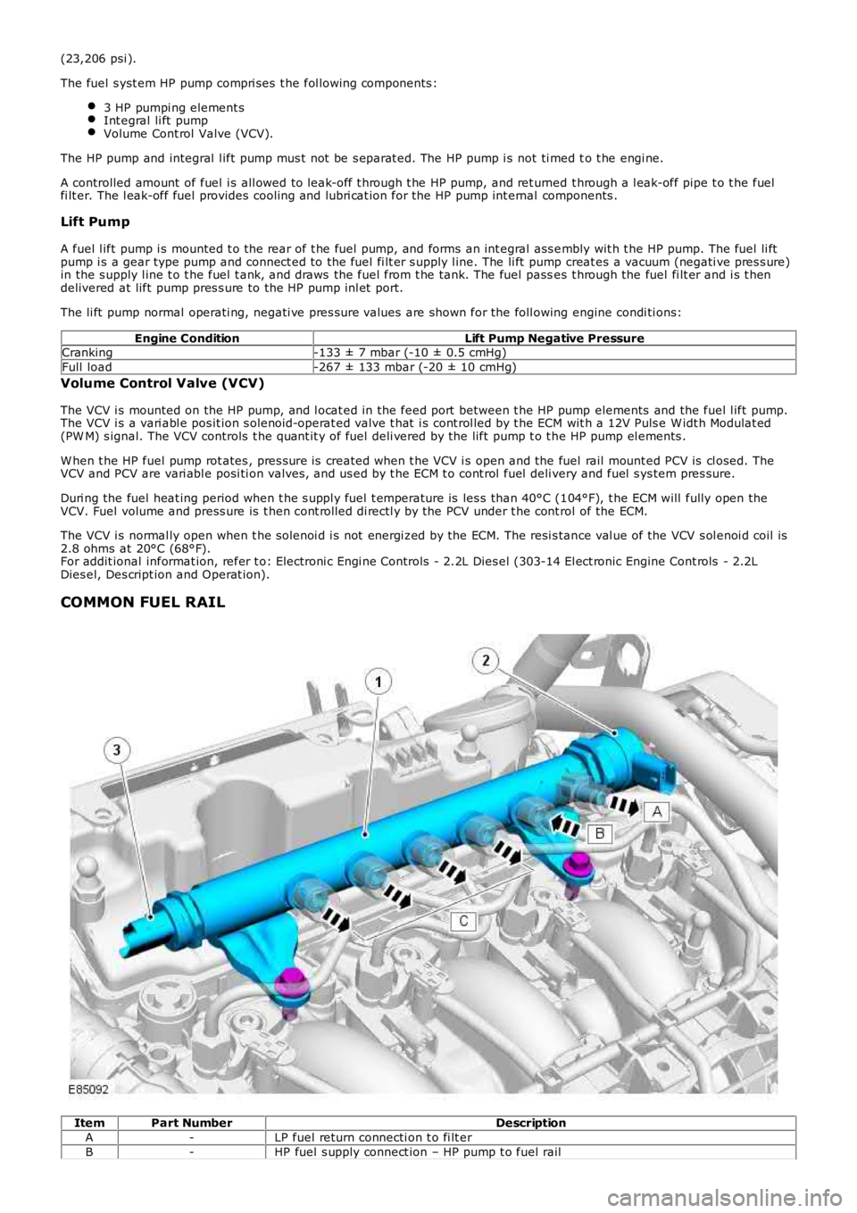
COMMON FUEL RAIL
ItemPart NumberDescription
A-LP fuel return connecti on t o fi lt er
B-HP fuel s upply connect ion – HP pump t o fuel rail
Page 998 of 3229
C-HP pipe connecti on – fuel rail t o inject or (4 off)
1-Fuel rail
2-PCV3-Fuel rail press ure sens or
The fuel rai l is manufact ured from forged st eel and secured t o t he cyl inder head with 2 fixings . The fuel rai l st orespres s urized fuel from t he HP pump, and prevent s pres s ure fluct uat ions i n the HP s ys tem. A fuel rail pres s ure s ens or and aPW M PCV are ins tall ed int o t he bore at each end of the fuel rail . The pres s ure s ensor i s ins tal led at t he acces sory dri veend of the fuel rail ; the PCV ins tal led at t he transmis s ion end of t he fuel rai l.
High-pres sure fuel pipes connect t he fuel rai l t o t he HP pump and fuel inject ors . A l eak-off pipe connect s the fuel rail t ot he fuel fi lt er return circui t.
The common fuel rail, fuel press ure s ens or and PCV form an int egral as s embly, and mus t not be separat ed. If a faultoccurs that requires component renewal, t hen t he compl ete fuel rail as s embl y mus t be renewed.
Fuel Rail Pressure Sensor
The fuel rai l pres sure s ens or is mount ed i n t he end of the fuel rail (access ory drive end) and connected to t he ECM vi a t heengi ne harnes s. The press ure sens or is provi ded wit h a 5V power s upply, ground and signal connect ions . The fuel railpres s ure s ensor i s a pi ezo-res is ti ve type s ens or contai ni ng an actuati ng diaphragm. Deflect ion of t he diaphragm provides aproport ional si gnal (output) volt age t o t he ECM, dependant on t he fuel pres s ure wit hin t he fuel rai l.
Pressure Sensor ParametersPressure Sensor Output VoltageFuel Rail Pressure
0.5V230 bar (3,336 ps i)
4.5V1,600 bar (23,206 ps i)The ECM compares t he s ens or s ignal vol tage t o s tored memory val ues, i n order t o cal cul ate the actual fuel pres s urepres ent in t he fuel rail. The ECM then us es t he fuel rai l press ure informat ion t o cont rol t he operati ng posi ti on of the VCVand PCV.For addit ional informat ion, refer t o: Electroni c Engi ne Controls - 2.2L Dies el (303-14 El ect ronic Engine Cont rols - 2.2LDies el, Des cript ion and Operat ion).
Pressure Control Valve (PCV)
The PCV i s mounted i n t he end of the fuel rail (trans mi s si on end) and connect ed t o the ECM via t he engine harnes s . ThePCV i s a s olenoid-operat ed valve cont rol led by a 12V PW M si gnal . The ECM operat es the PCV to adjus t t he fuel pres s urewit hin the fuel rail . Rel ieved fuel is direct ed through t he fuel rail leak-off pipe t o t he fuel fi lt er ret urn circui t. The l eak-offfuel als o provi des cooli ng and lubricat ion for t he PCV.For addit ional informat ion, refer t o: Electroni c Engi ne Controls - 2.2L Dies el (303-14 El ect ronic Engine Cont rols - 2.2LDies el, Des cript ion and Operat ion).
The PCV i s normall y open when t he s ol enoi d is not energi zed by the ECM. The resi s tance val ue of the PCV sol enoi d coi l is3.6 ohms at 20°C (68°F).
The PCV i s als o us ed by t he ECM t o provide di rect cont rol of the fuel sys tem, in t he fol lowi ng si tuat ions :
Duri ng s udden t rans ient phas es i n engine s peed (s uddenl y li ft ing off the accel erat or pedal, for example) where VCVact ion is not s ufficient to affect t he s uppl y of fuel to the fuel rail .To cont rol fuel press ure in t he event that the VCV fai ls .Duri ng the fuel heat ing period, when supply fuel temperat ure is l ess than 40°C (104°F). The VCV i s ful ly opened byt he ECM and t he HP pump compres s es a maximum quanti ty of fuel t o rais e t he fuel t emperature. The PCV is t henmodulat ed by the ECM to provide l eak-off fuel from the fuel rail t o t he fuel fi lt er ret urn circui t. The fuel i s t henrecircul ated t hrough t he fuel fi lt er and back t o t he HP pump.W hen t he fuel s uppl y t emperature is greater t han 70°C (158°F). The PCV is modul ated by t he ECM t o releas e fuelrai l pres sure, s ubs equentl y decreasi ng the fuel temperat ure to protect the fuel sys tem component s. Leak-off fuelfrom the fuel rail is direct ed to the fuel fil ter return ci rcuit and back t o the fuel tank.Duri ng engi ne s hut down t o progres s ively coll aps e fuel rail pres s ure.
FUEL INJECTORS
Page 999 of 3229
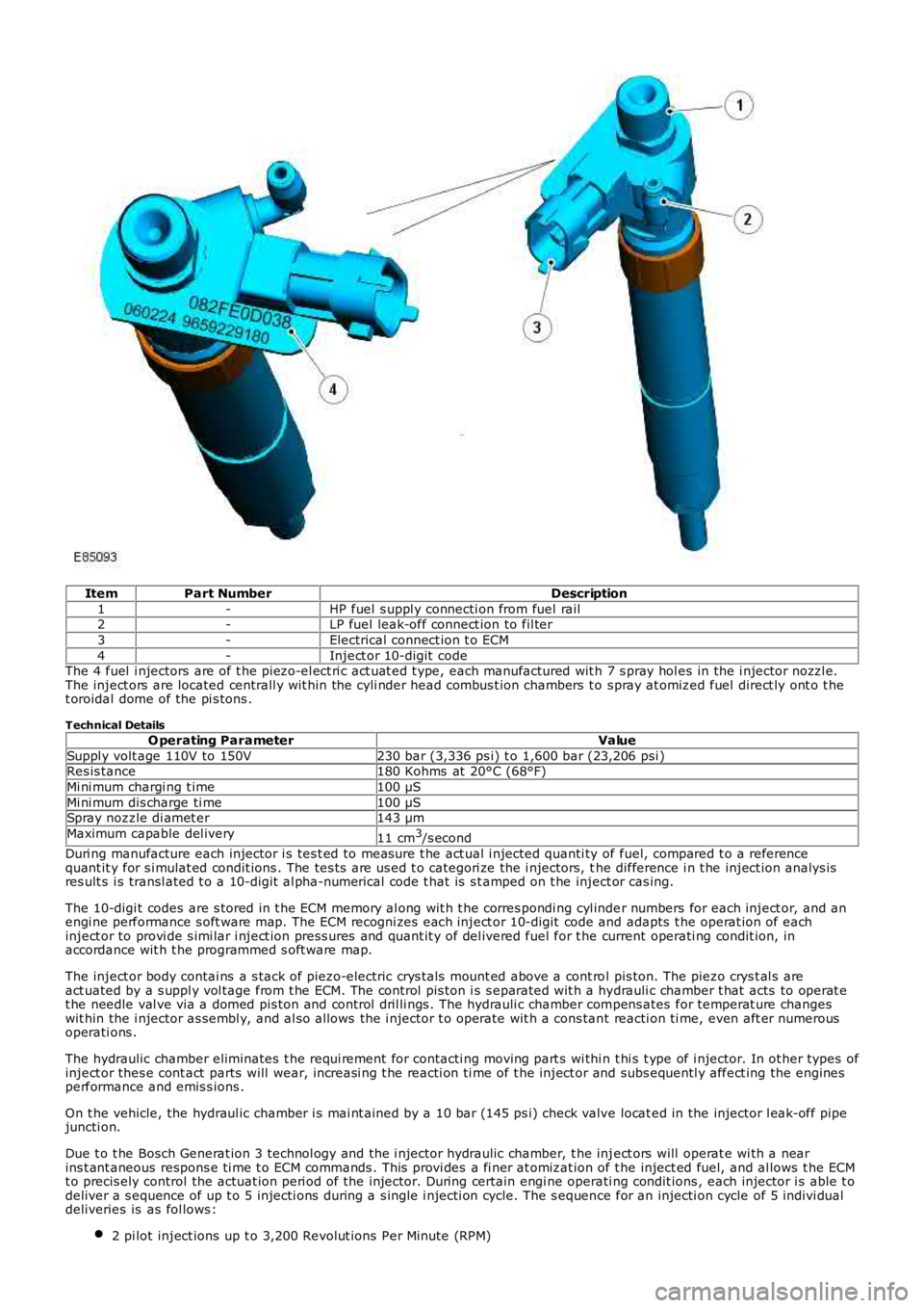
ItemPart NumberDescription
1-HP fuel s uppl y connecti on from fuel rail2-LP fuel leak-off connect ion to fil ter
3-Electrical connect ion t o ECM
4-Inject or 10-digit codeThe 4 fuel i njectors are of t he piezo-el ect ri c act uat ed t ype, each manufactured wit h 7 s pray hol es in the i njector nozzl e.The inject ors are located centrall y wit hin the cyli nder head combus t ion chambers t o s pray at omized fuel direct ly ont o t het oroidal dome of the pi s tons .
Technical Details
O perating ParameterValue
Suppl y volt age 110V to 150V230 bar (3,336 ps i) t o 1,600 bar (23,206 psi )Res is tance180 Kohms at 20°C (68°F)
Mi ni mum chargi ng t ime100 µS
Mi ni mum dis charge ti me100 µSSpray nozzle di amet er143 µm
Maximum capable del ivery11 cm3/s econd
Duri ng manufacture each injector i s tes t ed to measure t he act ual i njected quanti ty of fuel, compared t o a referencequant it y for s i mulat ed condit ions . The tes ts are us ed t o categori ze the i njectors, the difference i n t he inject ion analys isres ult s i s transl ated t o a 10-digit al pha-numerical code t hat is s t amped on t he inject or cas ing.
The 10-digi t codes are s tored in t he ECM memory al ong wit h t he corres pondi ng cyl inder numbers for each inject or, and anengi ne performance s oft ware map. The ECM recogni zes each inject or 10-digit code and adapts t he operat ion of eachinject or to provi de s imi lar i nject ion press ures and quant it y of del ivered fuel for the current operati ng condit ion, inaccordance wit h t he programmed s oft ware map.
The inject or body contai ns a s tack of piezo-electric crys t als mount ed above a cont rol pis ton. The piezo crys t al s areact uated by a s uppl y vol tage from t he ECM. The control pis ton i s s eparated wit h a hydrauli c chamber t hat acts to operat et he needle val ve via a domed pis ton and control dril li ngs . The hydrauli c chamber compens ates for temperat ure changeswit hin the i njector as sembl y, and al so allows the i njector t o operate wit h a cons tant reacti on ti me, even aft er numerousoperati ons .
The hydraulic chamber eliminates t he requi rement for contacti ng moving part s wi thi n t hi s t ype of i njector. In ot her types ofinject or thes e cont act parts will wear, increasi ng t he reacti on ti me of t he inject or and subs equentl y affect ing the enginesperformance and emis s ions .
On t he vehicle, the hydraul ic chamber i s mai nt ained by a 10 bar (145 ps i) check valve locat ed in the injector l eak-off pipejuncti on.
Due t o t he Bosch Generat ion 3 technol ogy and the i njector hydraulic chamber, t he inject ors will operat e wi th a nearins t ant aneous respons e ti me t o ECM commands . This provi des a fi ner at omizat ion of t he inject ed fuel, and al lows t he ECMt o precis ely control the actuat ion peri od of the injector. During certain engi ne operati ng condit ions , each injector i s able t odeliver a s equence of up t o 5 injecti ons during a s ingle i njecti on cycle. The s equence for an injecti on cycle of 5 indivi dualdeliveries is as fol lows :
2 pi lot inject ions up t o 3,200 Revolut ions Per Minute (RPM)
Page 1000 of 3229
1 control i njecti on up t o 4,500 RPM1 mai n i nject ion above 4,500 RPM2 pos t-inject ions duri ng DPF regenerati on phase (no l oad val ues ).
The pil ot injecti on phas e is deli vered ahead of t he mai n charge of fuel t o produce a s teady flame front , and create aprogres s ive pres s ure ri se in t he cylinder. The pi lot inject ion phas e reduces the l ag between t he i nject ion of fuel andcombus t ion occurri ng, al lowing the remaining charge of fuel t o be injected whi le combus ti on is taking pl ace. This i njecti onpri nci pl e creat es an increas e in power, and als o reduces combus t ion Noi se, Vibrati on and Hars hnes s (NVH) and exhaus temis s ions .
On vehicles i nst all ed wit h an exhaus t s ys tem DPF, t he high-press ure fueli ng s yst em provi des a post -injecti on phase of fuelint o t he combus t ion chambers . During the regenerat ion st age of the DPF, t he ECM all ows fuel t o be i nject ed aft er thecombus t ion s t roke and int o t he commencement of t he exhaus t st roke. The post -i njecti on phas e caus es fuel to burn i n theexhaus t s ys t em, creati ng high exhaus t gas t emperatures required to regenerate the DPF.
For addit ional informat ion, refer t o: Electroni c Engi ne Controls - 2.2L Dies el (303-14 El ect ronic Engine Cont rols - 2.2LDies el, Des cript ion and Operat ion) / Exhaus t Sys tem (309-00B Exhaust Sys tem - TD4 2.2L Dies el , Descripti on andOperat ion).
Injector Service Information
CAUTION: This t ype of inject or contai ns a hydraulic chamber. It is important that t he inject or is handled correct ly t oprevent the hydrauli c chamber from emptying. The i nject or is t o be capped and maint ained in an upri ght pos it ion, andmus t not be laid on t he si de or s haken.
Do not att empt t o remove carbon depos it s from t he dies el inject or nozzle.
The inject or is s upplied as a complete ass embly. The ori ginal inject or mus t not be separated.
• NOTE: The TD4 engine cyli nders are numbered from t he rear of t he engi ne (t rans mi ssi on end). Therefore, No. 1 cyli nderand No. 1 i nject or are l ocat ed at the rear of the engine.
A new copper washer mus t be ins t al led and t he old washer dis carded, whenever an inject or i s removed from t he cyl inderhead. The i njector cent eri ng ri ng may be re-us ed.
If an inject or i s removed, the injector mus t be i nst all ed to the original cyl inder, and does not require re-programming i ntot he ECM.
If an inject or i s renewed, the new inject or 10-digit code and corres pondi ng cyl inder number mus t be programmed i nto theECM, usi ng t he Land Rover approved di agnos ti c s yst em.
If the ECM is renewed, all 4 injector 10-di git codes and corres ponding cyli nder numbers must be programmed into the newECM, usi ng t he Land Rover approved di agnos ti c s yst em.
HIGH-PRESSURE FUEL AND LEAK-OFF PIPES
High-Pressure Fuel Pipe
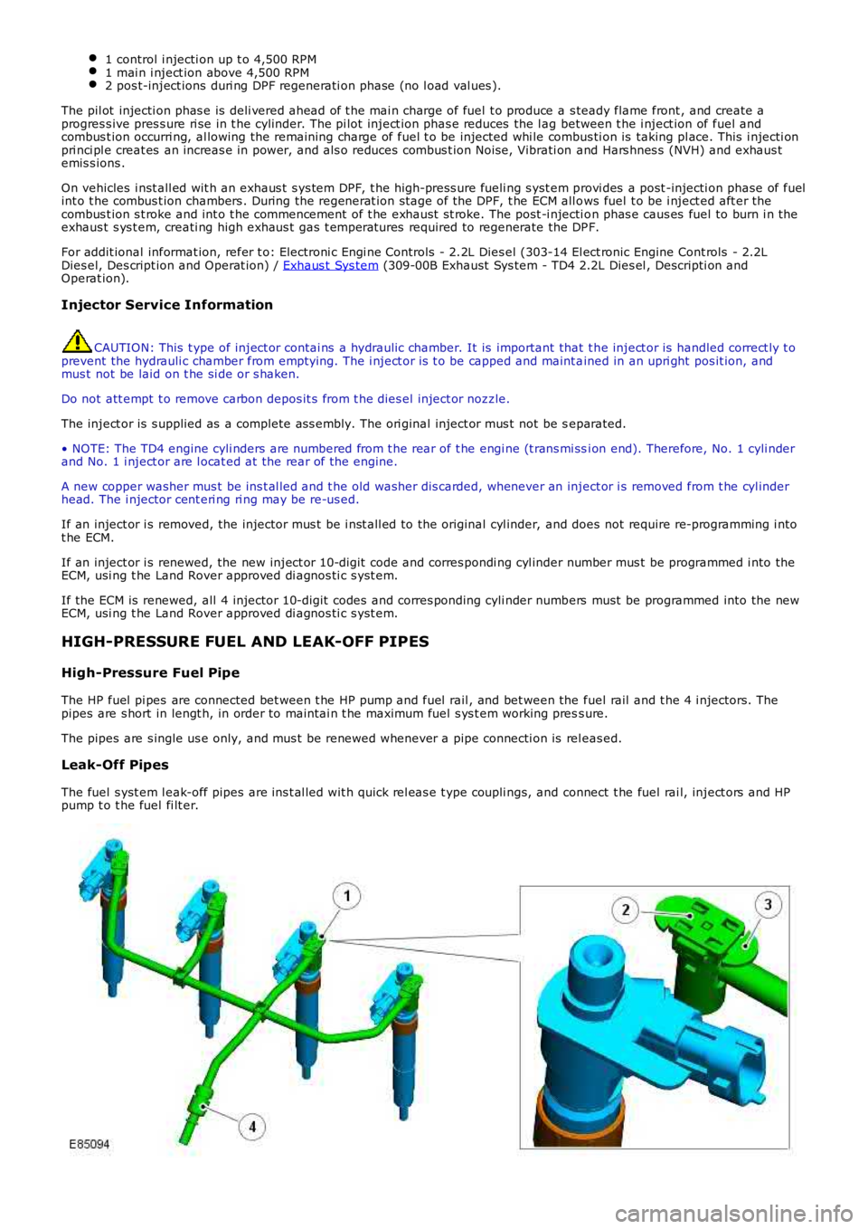
The HP fuel pi pes are connected bet ween t he HP pump and fuel rail , and bet ween the fuel rail and t he 4 i njectors. Thepipes are s hort in lengt h, in order to maintai n t he maximum fuel s ys t em working press ure.
The pipes are s ingle us e only, and mus t be renewed whenever a pipe connecti on is releas ed.
Leak-Off Pipes
The fuel s yst em l eak-off pipes are ins t al led wit h quick rel eas e t ype coupli ngs, and connect t he fuel rai l, inject ors and HPpump t o t he fuel fi lt er.