LAND ROVER FRELANDER 2 2006 Repair Manual
FRELANDER 2 2006
LAND ROVER
LAND ROVER
https://www.carmanualsonline.info/img/64/57251/w960_57251-0.png
LAND ROVER FRELANDER 2 2006 Repair Manual
Trending: load capacity, brake pads replacement, child lock, open gas tank, diagram, language, engine oil
Page 1051 of 3229
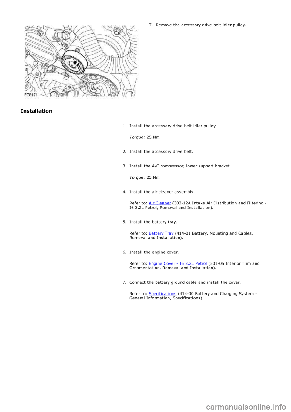
Remove t he acces sory dri ve bel t idl er pull ey.
7.
Installation Inst all t he acces sary dri ve bel t idl er pull ey.
T orque: 25 Nm 1.
Inst all t he acces sory dri ve bel t.
2.
Inst all t he A/C compress or, l ower support bracket.
T orque: 25 Nm 3.
Inst all t he air cleaner as s embly.
Refer t o: Air Cleaner (303-12A Intake Ai r Dis tribut ion and Fil tering -
I6 3.2L Pet rol, Removal and Ins t al lat ion).
4.
Inst all t he bat t ery t ray.
Refer t o: Bat t ery Tray (414-01 Bat tery, Mount ing and Cables ,
Removal and Ins tall ati on).
5.
Inst all t he engi ne cover.
Refer t o: Engi ne Cover - I6 3.2L Pet rol (501-05 Int eri or Trim and
Ornament ati on, Removal and Ins tal lat ion).
6.
Connect t he batt ery ground cable and ins tall t he cover.
Refer t o: Specificati ons (414-00 Bat tery and Charging Sys tem -
General Informat ion, Specificati ons).
7.
Page 1052 of 3229
Publi s hed: 11-May-2011
Accessory Drive - I6 3.2L Petrol - Accessory Drive Pulley
Removal and Inst all ati on
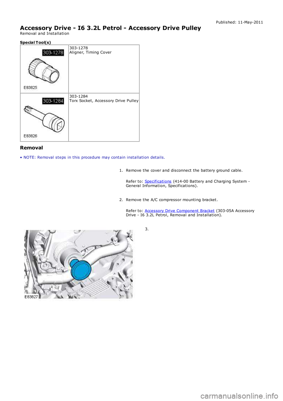
Special T ool(s)
303-1278Al igner, Timing Cover
303-1284Torx Socket, Acces s ory Drive Pull ey
Removal
• NOTE: Removal s t eps in t his procedure may cont ain i nst all ati on det ail s.
Remove t he cover and dis connect the bat tery ground cabl e.
Refer t o: Specificati ons (414-00 Bat tery and Charging Sys tem -General Informat ion, Specificati ons).
1.
Remove t he A/C compress or mounti ng bracket .
Refer t o: Acces sory Dri ve Component Bracket (303-05A Access oryDrive - I6 3.2L Pet rol , Removal and Ins t al lat ion).
2.
3.
Page 1053 of 3229
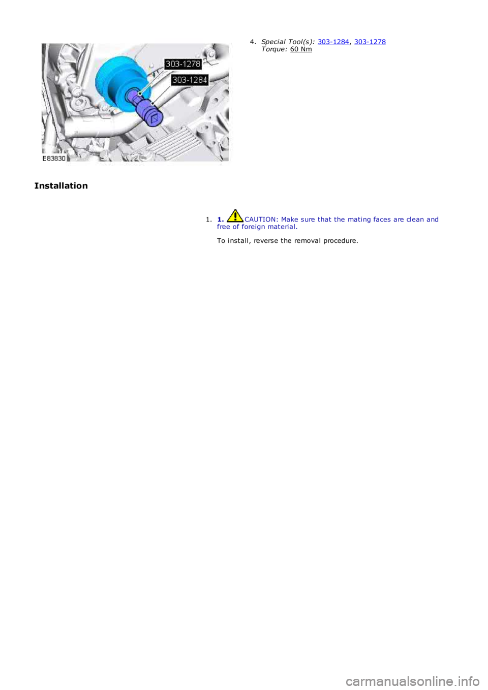
Speci al Tool (s ):
303-1284 ,
303-1278 T orque:
60 Nm 4.
Installation 1. CAUTION: Make s ure that the mati ng faces are cl ean and
free of foreign mat eri al.
To i nst all , revers e t he removal procedure.
1.
Page 1054 of 3229
Publi s hed: 11-May-2011
Accessory Drive - I6 3.2L Petrol - Accessory Drive Component Bracket
Removal and Inst all ati on
Special T ool(s)
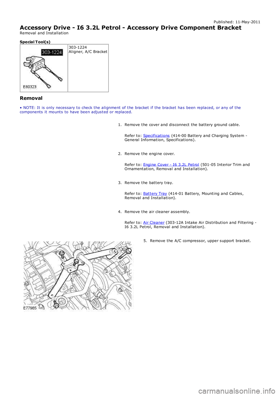
303-1224Al igner, A/C Bracket
Removal
• NOTE: It is only neces sary t o check t he ali gnment of t he bracket i f the bracket has been replaced, or any of t hecomponents it mount s to have been adjus t ed or replaced.
Remove t he cover and dis connect the bat tery ground cabl e.
Refer t o: Specificati ons (414-00 Bat tery and Charging Sys tem -General Informat ion, Specificati ons).
1.
Remove t he engi ne cover.
Refer t o: Engi ne Cover - I6 3.2L Pet rol (501-05 Int eri or Trim andOrnament ati on, Removal and Ins tal lat ion).
2.
Remove t he bat t ery t ray.
Refer t o: Bat t ery Tray (414-01 Bat tery, Mount ing and Cables ,Removal and Ins tall ati on).
3.
Remove t he air cleaner as s embly.
Refer t o: Air Cleaner (303-12A Intake Ai r Dis tribut ion and Fil tering -I6 3.2L Pet rol, Removal and Ins t al lat ion).
4.
Remove t he A/C compress or, upper s upport bracket.5.
Page 1055 of 3229
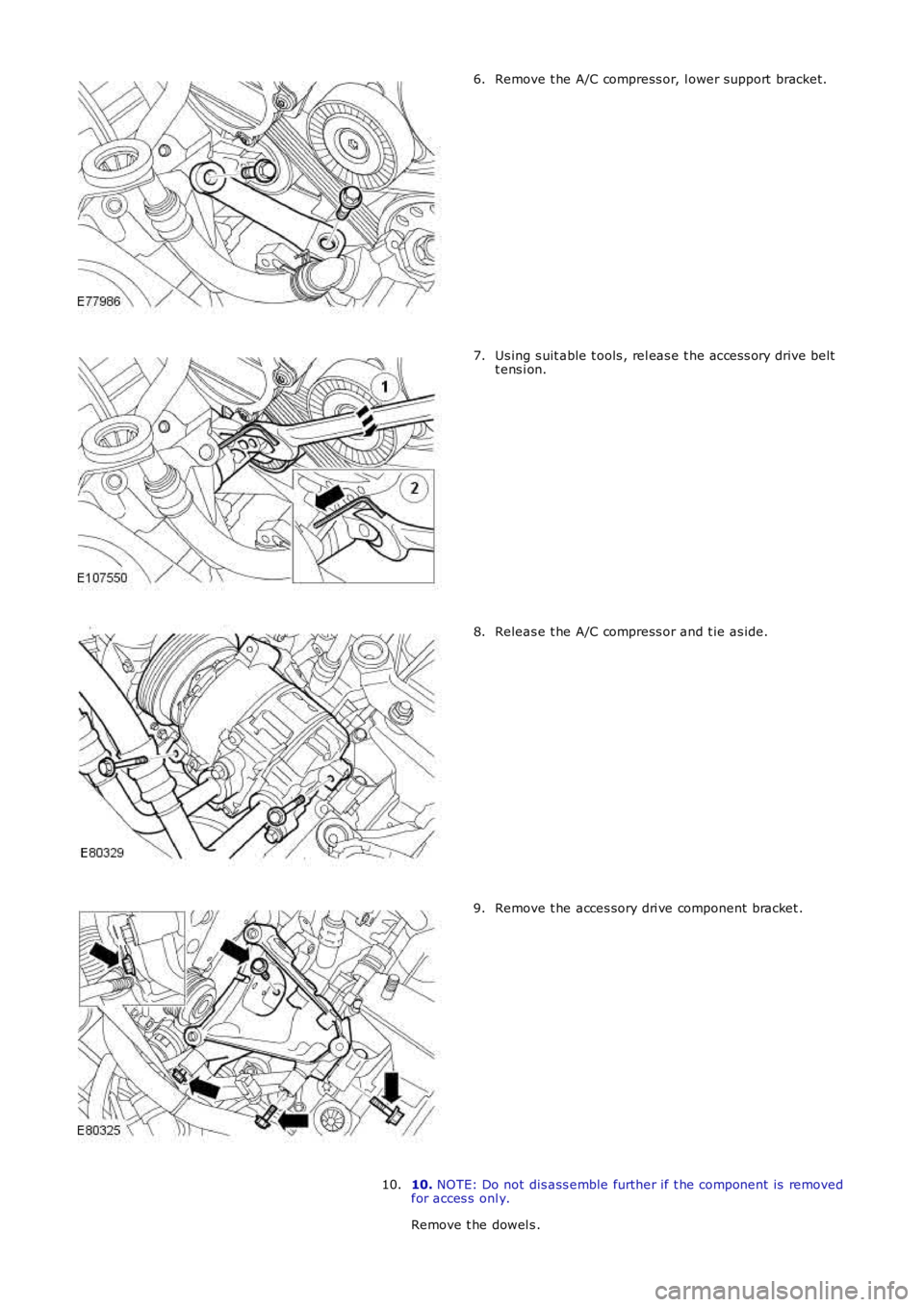
Remove t he A/C compress or, l ower support bracket.6.
Us ing s uit able t ools , rel eas e t he acces s ory drive beltt ens i on.7.
Releas e t he A/C compress or and t ie as ide.8.
Remove t he acces sory dri ve component bracket .9.
10. NOTE: Do not dis ass emble further if t he component is removedfor acces s onl y.
Remove t he dowel s .
10.
Page 1056 of 3229
Installation
Inst all t he dowel s .
1. 2.
NOTE: It i s only necess ary to check the al ignment of
t he bracket i f the bracket has been replaced, or any of
t he components it mounts to have been adjus t ed or
repl aced.
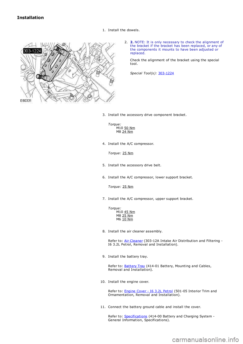
Check the al ignment of the bracket usi ng t he special
t ool .
Speci al Tool (s ): 303-1224 2.
Inst all t he acces sory dri ve component bracket .
T orque: M10 50 Nm M8
24 Nm 3.
Inst all t he A/C compress or.
T orque: 25 Nm 4.
Inst all t he acces sory dri ve bel t.
5.
Inst all t he A/C compress or, l ower support bracket.
T orque: 25 Nm 6.
Inst all t he A/C compress or, upper s upport bracket.
T orque: M10 45 Nm M8
25 Nm M6
10 Nm 7.
Inst all t he air cleaner as s embly.
Refer t o: Air Cleaner (303-12A Intake Ai r Dis tribut ion and Fil tering -
I6 3.2L Pet rol, Removal and Ins t al lat ion).
8.
Inst all t he bat t ery t ray.
Refer t o: Bat t ery Tray (414-01 Bat tery, Mount ing and Cables ,
Removal and Ins tall ati on).
9.
Inst all t he engi ne cover.
Refer t o: Engi ne Cover - I6 3.2L Pet rol (501-05 Int eri or Trim and
Ornament ati on, Removal and Ins tal lat ion).
10.
Connect t he batt ery ground cable and ins tall t he cover.
Refer t o: Specificati ons (414-00 Bat tery and Charging Sys tem -
General Informat ion, Specificati ons).
11.
Page 1057 of 3229
Publi s hed: 11-May-2011
Accessory Drive - I6 3.2L Petrol - Accessory Drive Shaft Front Seal
Removal and Inst all ati on
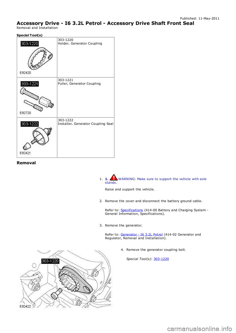
Special T ool(s) 303-1220
Hol der, Generator Coupl ing 303-1221
Pull er, Generat or Coupli ng 303-1222
Inst all er, Generator Coupli ng Seal
Removal 1. W ARNING: Make sure t o s upport the vehicle wit h axle
s tands .
Rais e and s upport t he vehi cl e.
1.
Remove t he cover and dis connect the bat tery ground cabl e.
Refer t o: Specificati ons (414-00 Bat tery and Charging Sys tem -
General Informat ion, Specificati ons).
2.
Remove t he generat or.
Refer t o: Generator - I6 3.2L Pet rol (414-02 Generator and
Regulator, Removal and Ins t allat ion).
3. Remove t he generat or coupli ng bolt .
Speci al Tool (s ): 303-1220 4.
Page 1058 of 3229
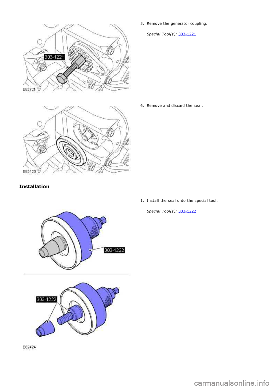
Remove t he generat or coupli ng.
Speci al Tool (s ): 303-1221 5.
Remove and dis card t he s eal.
6.
Installation Inst all t he s eal onto the s pecial tool.
Speci al Tool (s ): 303-1222 1.
Page 1059 of 3229
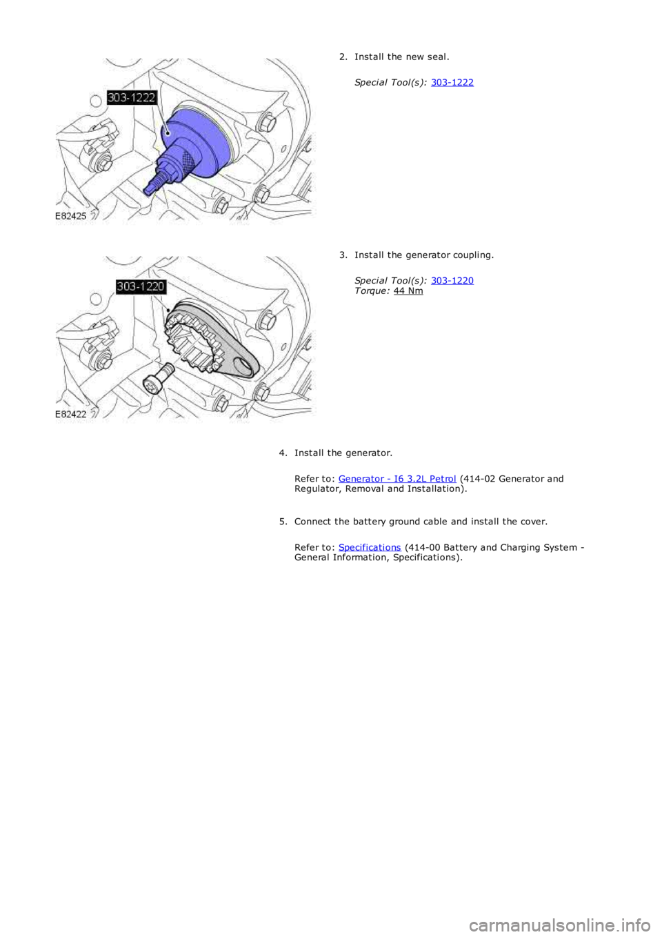
Inst all t he new s eal .
Speci al Tool (s ): 303-1222 2.
Inst all t he generat or coupli ng.
Speci al Tool (s ): 303-1220 T orque:
44 Nm 3.
Inst all t he generat or.
Refer t o: Generator - I6 3.2L Pet rol (414-02 Generator and
Regulator, Removal and Ins t allat ion).
4.
Connect t he batt ery ground cable and ins tall t he cover.
Refer t o: Specificati ons (414-00 Bat tery and Charging Sys tem -
General Informat ion, Specificati ons).
5.
Page 1060 of 3229
Publi s hed: 11-May-2011
Accessory Drive - I6 3.2L Petrol - Accessory Drive Shaft Rear Seal
Removal and Inst all ati on
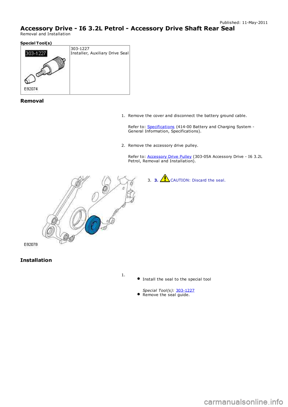
Special T ool(s) 303-1227
Inst all er, Auxili ary Drive Seal
Removal Remove t he cover and dis connect the bat tery ground cabl e.
Refer t o: Specificati ons (414-00 Bat tery and Charging Sys tem -
General Informat ion, Specificati ons).
1.
Remove t he acces sory dri ve pul ley.
Refer t o: Acces sory Dri ve Pulley (303-05A Acces s ory Drive - I6 3.2L
Petrol, Removal and Ins tall ati on).
2. 3. CAUTION: Di scard the s eal.
3.
Installation Inst all t he s eal t o t he s pecial t ool
Speci al Tool (s ): 303-1227 Remove t he s eal guide.1.
Trending: engine coolant, sport mode, fuse diagram, oil, key, oil change, oil dipstick
