LAND ROVER FRELANDER 2 2006 Repair Manual
Manufacturer: LAND ROVER, Model Year: 2006, Model line: FRELANDER 2, Model: LAND ROVER FRELANDER 2 2006Pages: 3229, PDF Size: 78.5 MB
Page 1101 of 3229
• NOTE: If aft er an uns ucces sful aut omati c res t art t he dri ver i s request ed t o res t art t he engi ne for example, by depres s ingt he cl utch. Thi s acti on has to be compl eted wi thi n 50 s econds , ot herwi se the St op/Start s yst em will deact ivat e and aconventi onal s tart wil l be required.
REFINEMENT AND DURABILITY
Engi ne operati ng refinement has been maint ai ned and in some cas es refined t o ens ure t he vehicle’s occupant s wit ness analmos t s eamles s operati on wi th regard t o engine s hutdown and rest art wit hi n a St op/St art cycle.
To reduce engine s hake when the engine is s hutt ing-down a revis ed t hrot tl e clos ing st rat egy i s i nt roduced, whi ch rampsdown t he fuel inject ion i n a more s moot h and cont rol led manner. At t he s ame t ime the generat or is t urned-off to reduceload on the engine.
ECM s oft ware changes and revis ed engine cali brati on further aid a s moother engi ne s hut down. Furthermore t he opti mizedengi ne mounti ng s trategy and t uni ng as si st s i n reducing engine s hake on engine s tart-up.
Component s direct ly i nvol ved wit h engine s tart-up and s hut-down have been ei ther upgraded or replaced to wit hst and t heincreas ed frequency of Stop/St art cycl es over t he l ifet ime of the vehicle. These enhanced and more robust component s aredis cus s ed i n thi s s ect ion.
CAUTION: To mai ntain the correct operat ion of t he St op/Start sys t em care must be taken when repl acingcomponents , t hat onl y approved parts are fit ted as some components from earl ier vehicl es wil l fi t the TD4_e.
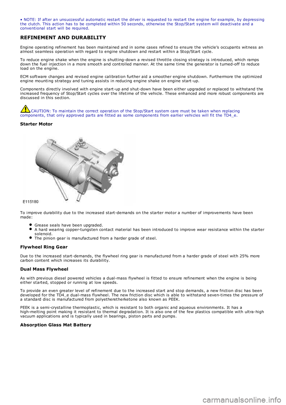
Starter Motor
To i mprove durabil it y due t o the increased st art -demands on t he s tarter mot or a number of i mprovements have beenmade:
Greas e s eals have been upgraded.A hard weari ng copper-tungs ten contact mat erial has been int roduced t o i mprove wear res i st ance wit hi n t he s tarters olenoi d.The pinion gear i s manufactured from a harder grade of st eel.
Flywheel Ring G ear
Due t o t he increas ed s tart -demands , the flywheel ri ng gear i s manufactured from a harder grade of st eel wit h 25% morecarbon cont ent which increas es it s durabil it y.
Dual Mass Flywheel
As wi th previ ous dies el powered vehicl es a dual -mass flywheel is fit ted to ens ure refi nement when the engine i s beingeit her s t art ed, s t opped or runni ng at low speeds.
To provide an even greater level of refi nement due t o t he i ncreas ed s tart and s top demands , a new fri ct ion di sc has beendevel oped for the TD4_e dual-mas s fl ywheel . The new frict ion dis c whi ch is able to wit hst and s even-t imes the press ure ofa s t andard dis c is manufact ured from polyetheret herketone als o known as PEEK.
PEEK is a s emi-cryst all ine t hermoplas ti c, whi ch is res is tant t o both organi c and aqueous environment s . It has ahigh-melt ing point making it res i st ant to thermal degradati on. It i s als o one of t he few pl ast ics compati ble wi th ult ra-hi ghvacuum appl icat ions and i s t ypi cal ly us ed in bearings , pi s ton part s and pumps .
Absorption Glass Mat Battery
Page 1102 of 3229
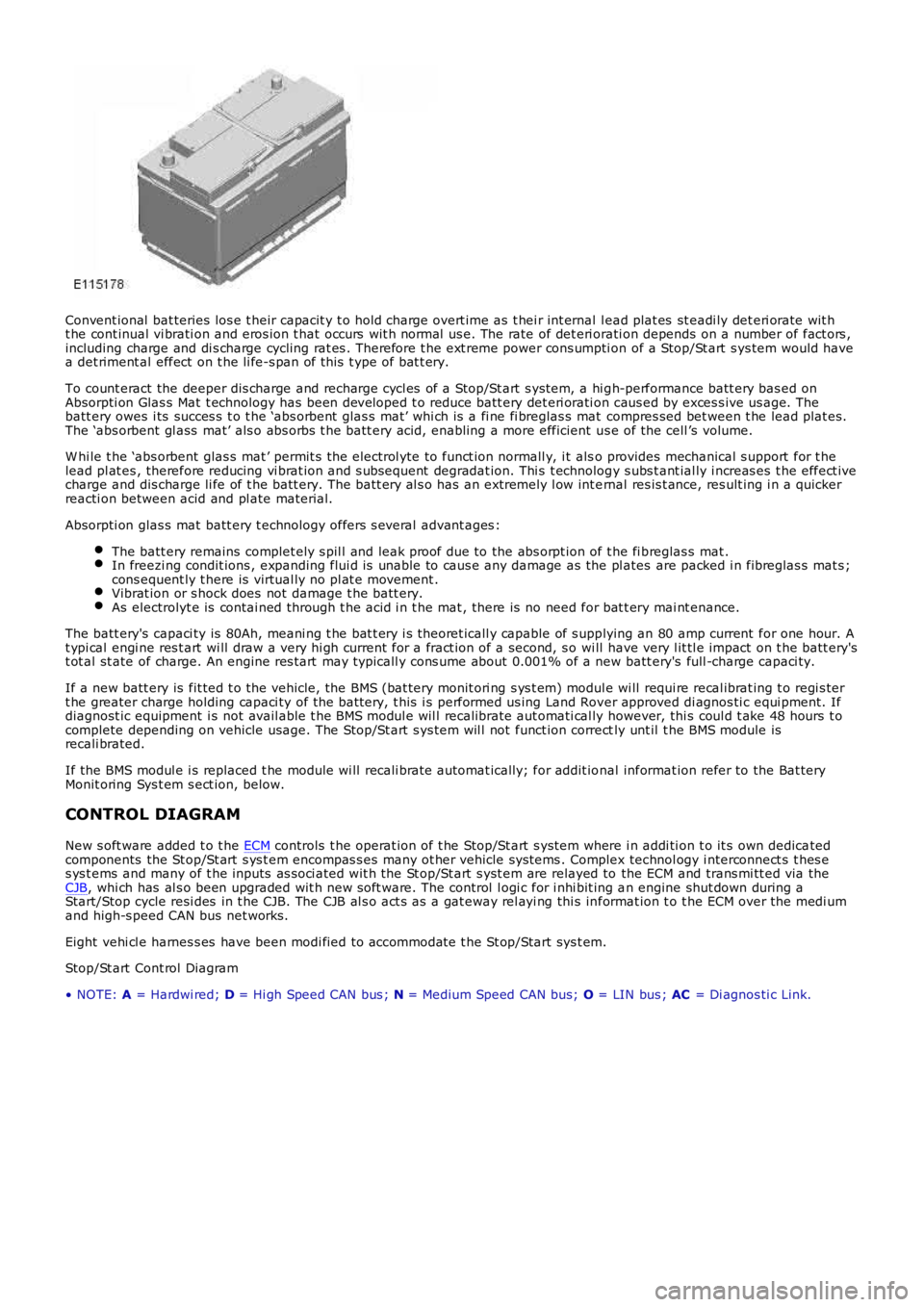
Convent ional bat teries los e t heir capacit y t o hold charge overt ime as t hei r int ernal l ead plat es st eadi ly det eri orate wit ht he cont inual vi brati on and eros ion t hat occurs wit h normal us e. The rate of det eri orati on depends on a number of fact ors ,including charge and di s charge cycling rat es . Therefore t he ext reme power cons umpti on of a Stop/St art s ys tem would havea det riment al effect on t he li fe-s pan of t his t ype of bat t ery.
To count eract the deeper dis charge and recharge cycl es of a Stop/St art s ys tem, a hi gh-performance batt ery bas ed onAbsorpti on Glas s Mat t echnology has been developed t o reduce batt ery det eri orati on caus ed by exces s ive us age. Thebatt ery owes i ts succes s t o t he ‘abs orbent glas s mat’ whi ch is a fi ne fi breglas s mat compres sed bet ween t he lead plat es.The ‘abs orbent gl ass mat’ als o abs orbs t he batt ery acid, enabling a more efficient us e of the cell ’s volume.
W hi le t he ‘abs orbent glas s mat ’ permit s t he electrol yte to funct ion normall y, i t also provides mechanical s upport for t helead pl at es , therefore reducing vi brat ion and s ubsequent degradat ion. Thi s t echnology s ubs t ant ial ly i ncreas es t he effect ivecharge and dis charge li fe of t he batt ery. The batt ery al s o has an extremely l ow int ernal res is t ance, res ult ing i n a quickerreacti on between acid and pl ate material.
Absorpti on glas s mat batt ery t echnology offers s everal advant ages :
The batt ery remains complet ely s pil l and leak proof due to the abs orpt ion of t he fi breglas s mat .In freezi ng condit ions , expanding flui d is unable to caus e any damage as the pl ates are packed i n fibreglas s mat s ;cons equent ly t here is virtual ly no pl at e movement .Vibrat ion or s hock does not damage t he batt ery.As electrolyt e is contai ned through t he acid i n t he mat , there is no need for bat t ery mai nt enance.
The batt ery's capaci ty is 80Ah, meani ng t he bat t ery i s theoret icall y capable of s upplying an 80 amp current for one hour. At ypi cal engi ne res t art wi ll draw a very hi gh current for a fract ion of a second, s o wi ll have very l it tl e impact on t he batt ery'st ot al st ate of charge. An engine res tart may typicall y cons ume about 0.001% of a new batt ery's full -charge capaci ty.
If a new batt ery is fit ted t o t he vehicle, the BMS (bat tery monit ori ng s ys t em) module wi ll requi re recal ibrat ing t o regi s tert he greater charge holding capaci ty of the bat tery, t his i s performed us ing Land Rover approved di agnos ti c equi pment. Ifdiagnost ic equipment i s not avail able t he BMS modul e wil l recalibrate aut omati cal ly however, thi s coul d t ake 48 hours t ocomplete depending on vehicle usage. The Stop/St art s ys tem wil l not funct ion correctly unt il t he BMS module isrecali brated.
If the BMS modul e i s replaced t he module wi ll recali brat e automat ically; for addit ional informat ion refer to the Bat teryMonit oring Sys t em s ect ion, below.
CONTROL DIAGRAM
New s oft ware added t o t he ECM controls t he operat ion of t he Stop/St art s yst em where i n addi ti on t o it s own dedicatedcomponents the St op/St art s ys t em encompas s es many ot her vehicle sys tems . Complex technol ogy i nterconnect s t hes es ys t ems and many of t he inputs as s oci ated wit h the St op/St art s yst em are relayed to the ECM and trans mi tt ed via theCJB, whi ch has al s o been upgraded wit h new s oft ware. The control l ogi c for i nhi bit ing an engine shut down during aStart/Stop cycle resi des in t he CJB. The CJB al s o act s as a gat eway rel ayi ng thi s informat ion t o t he ECM over the medi umand high-s peed CAN bus net works.
Eight vehi cl e harnes s es have been modi fied to accommodate t he St op/Start sys t em.
Stop/St art Cont rol Diagram
• NOTE: A = Hardwi red; D = Hi gh Speed CAN bus ; N = Medium Speed CAN bus; O = LIN bus ; AC = Di agnos ti c Link.
Page 1103 of 3229
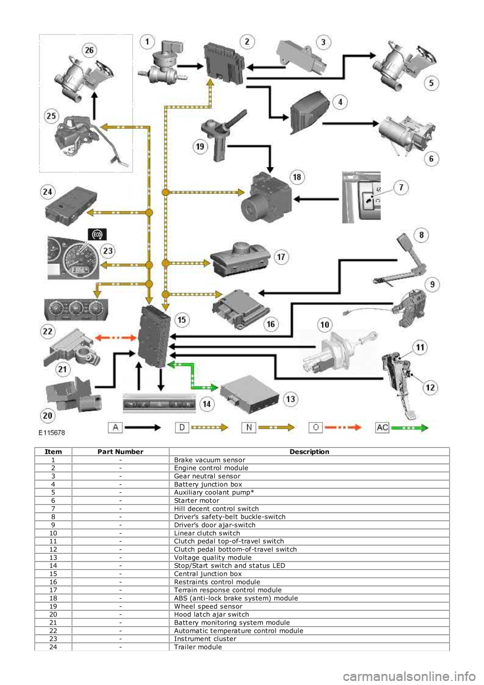
ItemPart NumberDescription
1-Brake vacuum s ens or2-Engine cont rol module
3-Gear neut ral s ens or
4-Batt ery junct ion box5-Auxili ary coolant pump*
6-Starter mot or
7-Hil l decent cont rol s wit ch8-Driver’s safety-bel t buckle-swi tch
9-Driver’s door ajar-s wi tch
10-Linear cl utch s wit ch11-Clut ch pedal t op-of-travel s wit ch
12-Clut ch pedal bott om-of-t ravel s wit ch
13-Volt age qual it y module14-Stop/Start swi tch and s t atus LED
15-Central junct ion box
16-Res trai nts control modul e17-Terrain respons e cont rol module
18-ABS (ant i-lock brake s ys tem) modul e
19-W heel s peed s ens or20-Hood lat ch ajar s wit ch
21-Batt ery moni toring s ys tem module
22-Automat ic t emperat ure control modul e23-Ins t rument clus ter
24-Trai ler module
Page 1104 of 3229
25-Fuel fired heat er (i f fi tt ed)
26-Auxili ary coolant pump **
* Vehicles wit hout fuel fired heat er.
** Vehicles wi th fuel fi red heater.
INTELLIGENT TECHNOLOGY
New and revi s ed components as di s cus s ed in this secti on have been developed t o ensure t hat al l vehicl e s ys t ems operatevirtuall y uninterrupt ed in a Stop/St art cycl e.
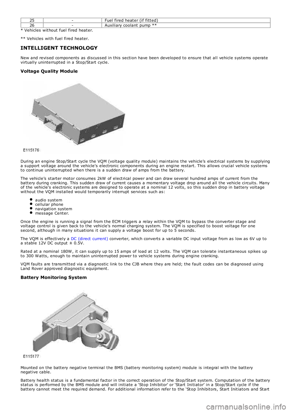
Voltage Quality Module
Duri ng an engine St op/Start cycle t he VQM (volt age qual it y module) mai ntains t he vehicle’s el ect ri cal s yst ems by s upplyinga s upport volt age around the vehicle's electroni c components during an engine res tart. This al lows crucial vehicle s ys temst o cont inue unint errupt ed when t here i s a s udden draw of amps from the bat tery.
The vehi cl e’s s t art er mot or cons umes 2kW of el ect ri cal power and can draw s everal hundred amps of current from thebatt ery during cranking. Thi s s udden draw of current causes a momentary volt age drop around al l t he vehicle ci rcuit s. Manyof the vehicle's electroni c s ys t ems are des i gned t o operat e at a nomi nal 12 volt s , so thi s s udden drop in bat tery volt agewit hout the VQM ins t al led woul d temporaril y i nt errupt servi ces such as :
audi o s yst emcel lul ar phonenavi gat ion sys temmes s age Cent er.
Once the engi ne is runni ng a s ignal from t he ECM triggers a relay wit hi n t he VQM t o bypass the converter s t age andvolt age control is gi ven back t o t he vehi cl e's normal charging sys tem. The VQM is specified t o boost vol tage for ones econd, alt hough i n many s it uati ons i t can s upply a volt age boos t for up t o 5 seconds .
The VQM is effecti vel y a DC (direct current) converter, which convert s a variable DC input vol tage from as l ow as 6V up t oa s t abl e 12V DC out put ± 0.5V.
Rated at a nominal 180W , it can s uppl y up t o 15 amps of load at 12 vol ts . The VQM can t olerat e i ns t ant aneous s pikes upt o 300 W at ts , enough to maintai n uninterrupt ed power t o vehicle s ys tems during engine cranking.
VQM fault s are trans mi tt ed via a diagnost ic l ink t o t he CJB where they are hel d; the fault codes can be di agnos ed us ingLand Rover approved diagnos t ic equipment .
Battery Monitoring System
Mounted on t he batt ery negat ive t ermi nal t he BMS (batt ery moni toring s yst em) module is i ntegral wi th t he batt erynegat ive cable.
Batt ery healt h s t at us i s a fundamental fact or in t he correct operat ion of t he Stop/St art s ys tem. Computat ion of t he batt erys tat us is performed by t he BMS module and will i nit iate a ‘St op Inhi bit or’ or ‘Start Ini ti at or’ i n a St op/Start cycle if t hebatt ery cannot meet t he requi red demand. For addit ional informati on refer to the ‘Stop Inhi bit ors , Start Init iat ors and St art
Page 1105 of 3229
Inhi bi tors ’ s ecti on, below.
The batt ery s t atus i nformat ion is t rans mit t ed from t he BMS modul e over t he LIN (l ocal i nt erconnect network) bus t o t heCJB which has a t wo-way communi cat ion wit h the BMS module. The cont rol l ogi c for i nhi bi ti ng engine s hutdown andini ti at ing an early engi ne res tart during a Start/Stop cycl e resi des in t he CJB. The CJB al so act s as t he gateway relayingt hi s informat ion t o t he ECM over the hi gh-s peed CAN bus.
Batt ery s t atus i nformat ion is al so trans mi tt ed from the CJB over the medi um-speed CAN bus t o t he ins t rument clus ter. Theins t rument clus ter dis plays batt ery charge warning mes s ages to indicate generat or or bat tery monit oring sys tem faul ts t ot he driver.
The BMS module cons tant ly computes t he s t at us of the el ect ri cal s ys tem on the bas is of the followi ng data:
batt ery det eriorati onbatt ery s t ate of chargebatt ery current demand.
If any of t hese factors s how a l ow meas urement, t he ECM s us pends t he Stop/Start feature unti l more bat tery power i savai lable. The fact ors are dis cus s ed below:
Batt ery det eriorati on
Alt hough fit t ed wit h a hi gh-performance batt ery bas ed on AGM (abs orpti on glas s mat ) technol ogy, t he charge holdingcapacit y of the bat tery wi ll s ti ll deteriorat e, however at a much s lower rat e t han a conventi onal bat tery. This degradat ionwil l reflect on the amount of charge t he bat t ery can hold unt il it reduces t o a condit ion where the bat tery wi ll needrepl acing.
The batt ery moni toring s yst em cal culat es t he condit ion of t he batt ery by obs erving a range of i nput s including:
ambient t emperaturecharge and dis charge act ivi tyvolt age andint ernal res is t ance.
The lat est condit ion value of t he batt ery i s s tored in the dedicated memory of t he BMS t o ens ure t he mos t accurat eforecas t of the bat teries condi ti on.
Stat e of charge
The BMS analys es how much charge has been drawn or repl enis hed to det ermi ne t he bat tery’s pres ent s tat e of charge.
Current demand
Duri ng a St op/Start cycle when vehicl e s ys t em us e i s in hi gh demand, for exampl e t he fol lowing are operat ing:
head li ght sclimate controlaudi o s yst em.
The batt ery wi ll dis charge more rapi dly due t o t he high current demand.
In thi s event t he BMS calculat es various fact ors t o determine how long t he batt ery can s upply a current at the presentlevel of demand. This calculat ion i s used by the CJB t o determine if t o authori ze whichever i s needed i n t he Stop/St artcycle, ei ther to:
prevent an engi ne s top, orini ti at e an engine res tart.
To provide this informati on t o t he CJB the BMS modul e calculates a range of batt ery variables , including:
s tat e of chargebatt ery s urface temperat ure to cal culat e t he int ernal temperat ureint ernal res is t ancevolt agecurrent flow into and from t he batt ery.
The batt ery moni toring s yst em cal culat es t hes e vari abl es agai nst programmed det ailed bat tery li fe model s t o determinehow l ong the gi ven current can be s upport ed.
Batt ery moni toring s ys tem modes
The batt ery moni toring s yst em has three di s ti nct modes :
Acti ve mode: during normal vehicle operat ion, batt ery dat a i s upl oaded and calculat ed every s econd.Sleep mode: duri ng ignit ion off, bat tery dat a i s uploaded every s econd and calculated every hour t o reduce i nacti vecurrent drai n.Trans port mode: bat t ery moni tori ng int ervals are mi nimi zed.
Batt ery replacement
If a new batt ery is fit ted t o t he vehicle, the BMS (bat tery monit ori ng s ys t em) module wi ll requi re recal ibrat ing t o regi s tert he greater charge holding capaci ty of the bat tery, t his i s performed us ing Land Rover approved di agnos ti c equi pment. If adiagnost ic s ys tem is not avail abl e t he BMS module will recal ibrat e automat icall y however, this could take 48 hours tocomplete depending on vehicle usage. The Stop/St art s ys tem wil l not funct ion correctly unt il t he BMS module isrecali brated.
If the BMS modul e i s replaced t he module wi ll re-calibrate aut omati cal ly.
Page 1106 of 3229
CAUTION: To avoid damage/malfuncti oni ng of the BMS module, always us e a s uit able body ground point rather thant he bat t ery negat ive terminal when connect ing a s lave power supply.
For addit ional informat ion, refer t o: Batt ery (414-01 Bat tery, Mounti ng and Cables , Diagnos is and Tes t ing).
Gear Neutral Sensor
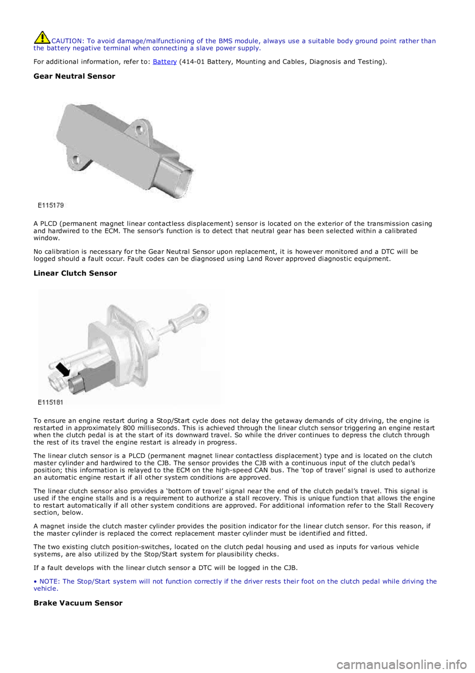
A PLCD (permanent magnet l inear cont act les s dis placement) s ensor i s located on the exterior of the trans mi s si on cas i ngand hardwired t o t he ECM. The sens or’s functi on is t o det ect t hat neut ral gear has been s elected wi thi n a cali bratedwindow.
No cali brati on is neces sary for t he Gear Neut ral Sensor upon repl acement, i t is however monit ored and a DTC wil l belogged s houl d a fault occur. Fault codes can be diagnos ed us ing Land Rover approved di agnos ti c equi pment.
Linear Clutch Sensor
To ens ure an engine res tart during a St op/St art cycl e does not del ay the get away demands of cit y dri ving, the engine i sres t art ed in approximately 800 mil li seconds . This i s achi eved through t he li near clut ch s ens or triggeri ng an engine rest artwhen t he cl utch pedal is at t he s tart of i ts downward t ravel. So whil e t he dri ver conti nues t o depres s t he clutch t hrought he res t of it s t ravel t he engine rest art i s already i n progress .
The li near clut ch s ens or is a PLCD (permanent magnet li near contactl es s di spl acement) type and i s located on t he clut chmas ter cylinder and hardwired t o t he CJB. The s ensor provi des t he CJB wi th a cont inuous input of the clut ch pedal ’sposi ti on; this informati on is relayed t o t he ECM on t he high-speed CAN bus . The ‘t op of travel ’ si gnal i s used to aut horizean automat ic engine res tart if all ot her s ys tem condit ions are approved.
The li near clut ch s ens or als o provides a ‘bott om of t ravel’ s ignal near t he end of the cl ut ch pedal ’s t ravel. This si gnal i sus ed if t he engi ne s tal ls and i s a requi rement t o authori ze a s tal l recovery. This is unique funct ion t hat allows the enginet o res t art automat ically if all ot her s ys tem condit ions are approved. For addi ti onal i nformat ion refer t o t he Stall Recoverys ect ion, below.
A magnet ins ide the clut ch mas ter cylinder provides t he posi ti on indicator for the linear cl utch s ensor. For t his reason, ift he mas ter cyl inder is replaced the correct replacement mas t er cyli nder mus t be i dent ified and fit t ed.
The t wo exis ti ng clutch pos it ion-s wi tches, l ocat ed on t he cl utch pedal hous ing and us ed as i nput s for vari ous vehi cl es ys t ems , are al so ut il ized by t he Stop/Start sys tem for pl aus ibi lit y checks .
If a fault develops wi th the l inear cl utch s ensor a DTC wil l be logged in the CJB.
• NOTE: The Stop/Start sys tem wil l not funct ion correctl y if t he dri ver rest s t hei r foot on t he clut ch pedal whil e dri vi ng t hevehi cl e.
Brake Vacuum Sensor
Page 1107 of 3229
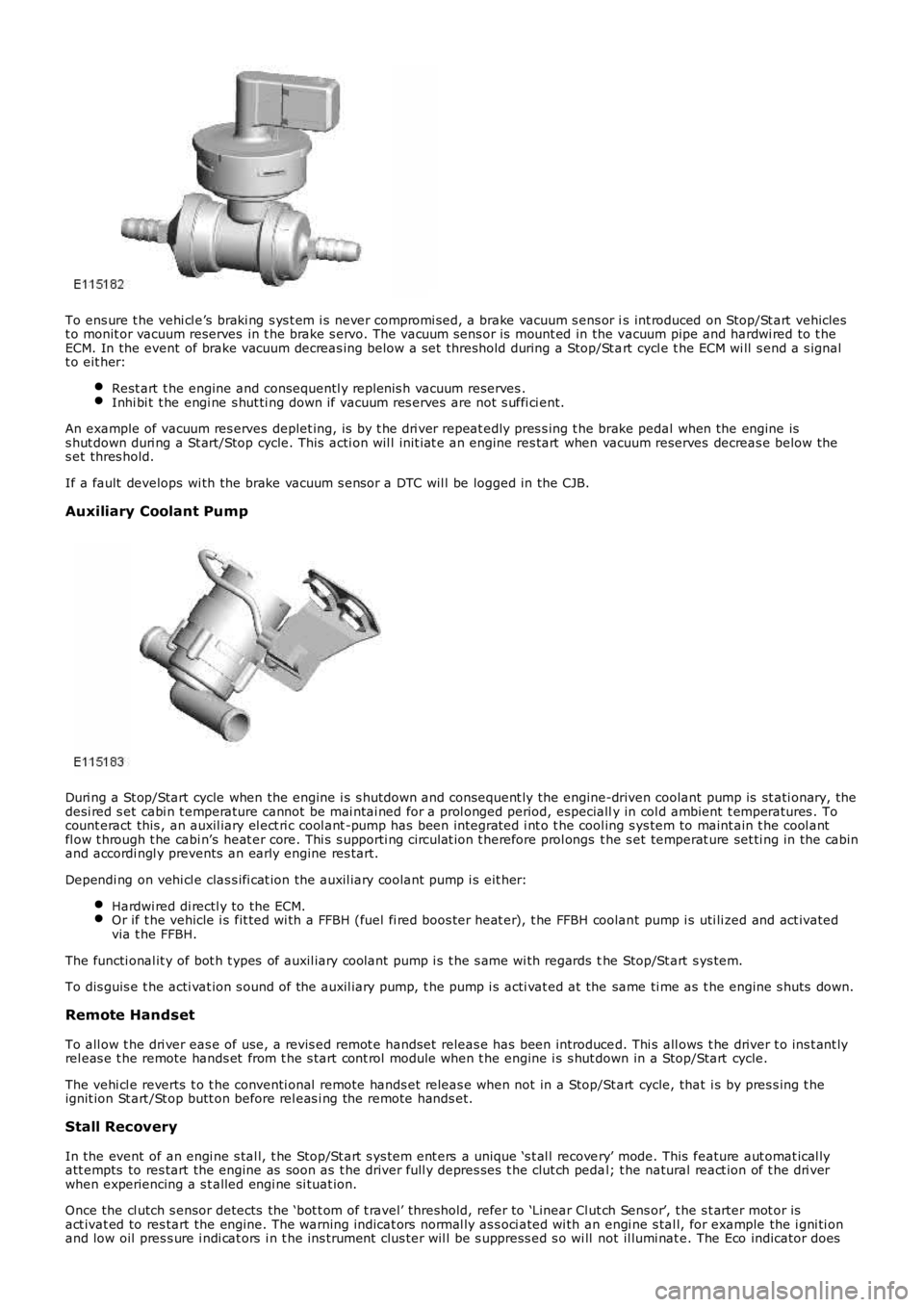
To ens ure t he vehi cl e’s braki ng s ys t em i s never compromi sed, a brake vacuum s ens or is int roduced on Stop/St art vehiclest o monit or vacuum reserves in t he brake s ervo. The vacuum sens or is mount ed in the vacuum pipe and hardwi red to t heECM. In the event of brake vacuum decreas ing below a s et threshold during a Stop/St art cycl e t he ECM wi ll s end a s ignalt o eit her:
Rest art t he engine and consequentl y replenis h vacuum reserves .Inhi bi t t he engi ne s hut ti ng down if vacuum res erves are not s uffi ci ent.
An example of vacuum res erves deplet ing, is by t he dri ver repeat edly pres s ing t he brake pedal when the engine iss hut down duri ng a St art/Stop cycle. This acti on wil l init iat e an engine res tart when vacuum reserves decreas e below thes et thres hold.
If a fault develops wi th the brake vacuum s ensor a DTC wil l be logged in the CJB.
Auxiliary Coolant Pump
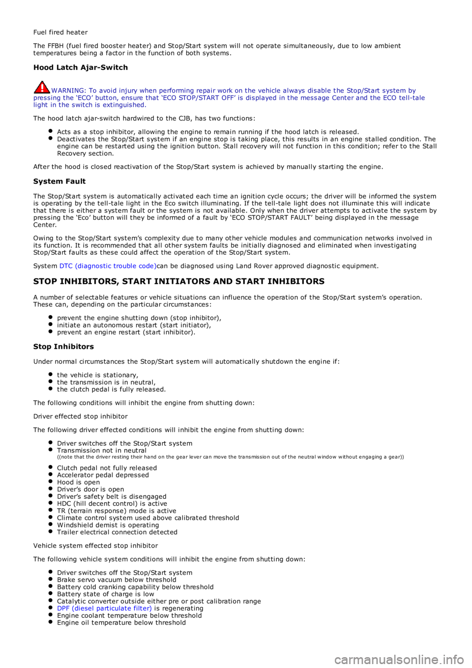
Duri ng a St op/Start cycle when the engine i s s hutdown and consequent ly the engine-driven coolant pump is st ati onary, thedesi red s et cabi n t emperature cannot be mai ntai ned for a prol onged period, especially in col d ambient t emperatures . Tocount eract this , an auxil iary el ect ri c cool ant -pump has been integrat ed i nt o t he cool ing s ys tem to maint ain t he cool antfl ow t hrough t he cabi n’s heat er core. Thi s s upporti ng ci rculat ion t herefore prol ongs t he s et temperat ure set ti ng in the cabinand accordi ngl y prevents an early engine res tart.
Dependi ng on vehi cl e clas s ifi cat ion the auxil iary coolant pump i s eit her:
Hardwi red di rectl y to the ECM.Or if t he vehicle i s fit ted wi th a FFBH (fuel fi red boos ter heat er), t he FFBH coolant pump i s uti li zed and act ivatedvia t he FFBH.
The functi onal it y of bot h t ypes of auxil iary coolant pump i s t he s ame wi th regards the Stop/St art s ys tem.
To dis guis e t he acti vat ion s ound of the auxil iary pump, t he pump i s acti vat ed at the same ti me as t he engine s huts down.
Remote Handset
To all ow t he dri ver eas e of use, a revis ed remot e handset releas e has been introduced. Thi s all ows t he driver t o ins t ant lyrel eas e t he remote hands et from t he s tart cont rol module when t he engine i s s hut down in a Stop/Start cycle.
The vehi cl e reverts t o t he conventi onal remote hands et releas e when not in a Stop/Start cycle, that i s by pres s ing t heignit ion St art /St op butt on before rel eas i ng the remote hands et.
Stall Recovery
In the event of an engi ne s tal l, t he Stop/St art s ys tem ent ers a unique ‘s t al l recovery’ mode. This feature aut omat ical lyatt empts to res tart the engine as soon as t he driver full y depres ses t he clut ch pedal; t he natural react ion of t he dri verwhen experiencing a s t alled engi ne si tuat ion.
Once the cl utch s ensor detects the ‘bot t om of t ravel’ threshold, refer to ‘Linear Clut ch Sens or’, t he s t arter mot or isact ivat ed to res tart the engine. The warni ng indicat ors normal ly as s oci ated wi th an engi ne s tal l, for example the i gni ti onand low oil pres s ure i ndi cat ors i n t he ins t rument clus ter wil l be s uppress ed s o wi ll not il lumi nat e. The Eco indicator does
Page 1108 of 3229

however remain i ll uminated.
A ‘st all recovery’ event is the onl y s tat e when t he Stop/St art s yst em wil l permit t he engine t o be s t art ed when thet ransmis s ion i s in gear; hence t he requirement for t he cl utch pedal to be full y depres sed. If the s t all recovery fai ls and t heengi ne does not res tart, t he dri ver wi ll be reques ted vi a t he Mess age Center t o ‘s elect neutral ’ to at t empt anot her rest art .
If the engine does not res t art aft er thi s request t he ‘st all recovery’ mode wil l ti me-out and deact ivate. At t his point t he‘Eco’ i con in t he i ns t rument panel wi ll exti ngui sh and the light s usual ly as s ociat ed wi th an engi ne st all wi ll il lumi nat e. As ares ult t he dri ver will be requi red to perform a convent ional engi ne res tart.
Alt hough st all recovery i s a feat ure of t he St op/Start sys t em i t is pos si ble for it t o acti vat e i ndependent ly from t heStop/St art parameters . For exampl e:
If the St op/Start s ys t em has been deact ivated by the driver st all recovery wi ll s ti ll funct ion.Stal l recovery wil l act ivate at ambi ent temperat ures as l ow as (minus ) - 2°C, whereas the St op/Syst em operat ingt emperature threshold is above 4°C.Different t o t he operat ion of t he Stop/St art s yst em, s tal l recovery wil l st il l functi on when the vehicle is t owing;refer to the ‘Trail er Towi ng’ s ect ion.
• NOTE: As t he neces s ary cri teria will not have been sat is fi ed when t he vehi cl e i s at the beginning of a journey s t allrecovery wi ll not functi on. For exampl e, if t he vehi cl e s tal ls when l eavi ng the garage or driveway a convent ional engineres t art wi ll be required.
Trailer Towing
The Stop/St art s ys tem wil l aut omati cal ly di sabl e when t rail er light s are det ect ed by t he CJB via s ignals from t he t rail ermodule, t hi s informat ion i s t hen trans mi tt ed t o t he ECM. It i s not pos s ibl e for t he s ys t em t o det ect when a trai ler powerplug i s ins ert ed i n the vehicl e’s t owi ng s ocket s o it us es operat ion of t he trail er l ights as it s indi cat or.
The t rail er towing sys tem inhi bi ts St op/St art as i t is pos s ible that trail er power requirements could interfere wit h t heoperati on of the bat tery monit ori ng s ys t em. In parti cul ar, a t rai ler batt ery could revers e t he feed current t o t he vehicleduri ng an engi ne cranking event , t hi s coul d pos si bly:
Confus e t he bat t ery monit ori ng s ys t em i nto det ect ing an unreal is t ically smal l current at engi ne cranking.Rupture the fus e as sociat ed wit h t he t rail er modul e.
Climate Control System
• NOTE: The ‘ECON’ butt on has been renamed ‘A/C’ to prevent confus ion wi th the St op/St art s yst em ‘Eco’ s wit ch.
A number of changes have been made to the l ogi c and operati on of climat e control system, wit hi n a St op/St art cycle to:
maint ain occupant comfortprevent winds hi eld mis ti ngcons erve bat tery power.
This has been achi eved by the ATC (automat ic t emperat ure control) module monit oring and varyi ng, as necess ary variousclimate control funct ions wi thi n a St op/Start cycle.
In s ome circums t ances t he ATC has t he capabil it y to inhibit an engi ne s hut down or init iat e an engine rest art wit hi n aStop/St art cycle. Thi s i s achi eved by t he ATC module communi cat ing wit h t he CJB on the medi um s peed CAN. The variousoverri de functi ons the ATC has in a St op/St art cycl e are di s cus s ed bel ow:
Coolant temperat ure
The ATC module wil l i nhibit an engine shut down or i nit iat e an engine res t art wi thi n a St op/Start cycle if t he coolantt emperature fal ls below the calculat ed t hreshol d to s upport t he cabin t emperat ure s et by t he vehi cl e occupant s .
W i nds hiel d demis t ing
The variant of cli mate control fi tt ed t o the vehicl e influences t he s oft ware changes that have been made. For exampl e, thebase cl imat e-control s ys tem does not have a humi dit y s ens or, as us ed on a highline sys tem t o ini ti at e a winds hi elddemis t . Therefore, a calculat ion for demis ti ng the winds hi eld i s made us ing t he s ignals from t he rai n s ens or and ambientt emperature s ens or. Us i ng the probabi lit y t hat windshi eld mis ti ng wil l occur if i t is raining and t he ambi ent t emperat ure i scool , the ATC wil l presume a wi nds hiel d demis t is required and s tart the engine when i n a St op/St art cycl e.
Evaporat or temperat ure the main cause of windshi eld mis ti ng is al s o monit ored and t he high-line cl imat e cont rol s yst emwil l periodicall y cool t he evaporat or as neces s ary t o reduce mi s ti ng during a Stop/St art cycl e. The sys tem operates thewinds hield demis t s hut ter and i f the evaporator i s wet t he shut ter wi ll remai n clos ed for a few seconds after an engineres t art unti l the vapor is di ss ipat ed.
If the driver sel ect s eit her ‘programmed defros t ’ or t he ‘wi ndshi el d heater’ i t is as s umed t hat a qui ck demis t of thewinds hield is requi red. Therefore, t he ATC vi a the CJB will ei ther: i nhibit an engine shut down or i nit iat e an engine res t art .
Heater fan speed
Duri ng an engine s hutdown t he ATC monit ors cabin temperat ure and maint ai ns the fan speed at a l evel that wi ll cons erve,for as l ong as poss ibl e t he heat i n t he core of t he cabi n heat er. If the driver s elect s a hi gher fan s peed and the heatcannot be mai ntained i n t he heat er core, the engine will rest art .
Heated rear window and heated s eats
If the heated rear window or heated s eats are acti ve or act ivated during an engine shut down event t he power out put oft he relevant s ys t em wi ll be i nt errupted unt il the engi ne is rest art ed. The tell -t ale light i n t he relevant s wit ch wil lil lumi nat e t o i ndi cat e t he s ys t em i s act ive even t hough the s ys tem is recei vi ng no power. This feature is us ed t o conservebatt ery power.
Page 1109 of 3229
Fuel fired heat er
The FFBH (fuel fired boost er heat er) and St op/Start s ys t em wi ll not operate si mult aneous ly, due to low ambientt emperatures bei ng a fact or in t he funct ion of both sys tems .
Hood Latch Ajar-Switch
W ARNING: To avoi d injury when performing repai r work on t he vehicle al ways di s abl e the Stop/St art s ys tem bypres s ing t he ‘ECO’ butt on, ens ure that ‘ECO STOP/START OFF’ is di s pl ayed in t he mes sage Cent er and the ECO tel l-taleli ght in t he s wit ch is ext inguis hed.
The hood lat ch ajar-s wit ch hardwired to the CJB, has two functi ons :
Acts as a s top i nhi bit or, all owing t he engi ne t o remai n running if t he hood latch i s rel eased.Deact ivates the St op/Start s ys t em i f an engi ne s top i s t aki ng place, t his res ul ts in an engine st all ed condit ion. Theengi ne can be res t art ed usi ng t he ignit ion but ton. Stal l recovery wil l not funct ion i n t hi s condi ti on; refer t o t he StallRecovery secti on.
Aft er the hood i s clos ed reacti vat ion of t he Stop/Start sys tem is achieved by manuall y s tarti ng the engine.
System Fault
The Stop/St art s ys tem is aut omati cal ly acti vat ed each ti me an ignit ion cycl e occurs; t he dri ver will be i nformed t he sys t emis operat ing by the t ell -t ale l ight in the Eco s wi tch i lluminati ng. If the tell -t ale light does not il luminat e t hi s wi ll indicat et hat t here i s eit her a s ys t em faul t or the sys tem is not avail abl e. Onl y when t he dri ver at tempt s t o act ivat e t he sys t em bypres s ing t he ‘Eco’ but ton will t hey be informed of a fault by ‘ECO STOP/START FAULT’ being di spl ayed i n t he mes sageCenter.
Owi ng to the St op/Start s ys t em’s complexit y due t o many ot her vehicle modul es and communicat ion net works i nvol ved i nit s funct ion. It i s recommended t hat al l ot her sys tem faul ts be init ial ly diagnos ed and eliminated when inves t igati ngStop/St art fault s as t hes e could affect the operat ion of t he St op/Start sys tem.
Syst em DTC (di agnos ti c troubl e code)can be diagnos ed us ing Land Rover approved di agnos ti c equi pment.
STOP INHIBITORS, START INITIATORS AND START INHIBITORS
A number of s el ect able feat ures or vehicle si tuat ions can infl uence t he operat ion of t he Stop/St art s yst em’s operati on.Thes e can, depending on the parti cular circumst ances :
prevent the engine s hutt ing down (s t op inhibi tor),ini ti at e an aut onomous res tart (s tart ini ti at or),prevent an engi ne res t art (st art i nhi bit or).
Stop Inhibitors
Under normal ci rcums tances the St op/St art s ys t em wi ll automat icall y s hut down t he engi ne if:
t he vehi cl e is st ati onary,t he trans mi s si on is in neutral,t he cl utch pedal i s ful ly releas ed.
The fol lowing condit ions wi ll inhibi t the engine from s hutt ing down:
Dri ver effected st op inhi bi tor
The fol lowing driver effect ed condi ti ons will i nhi bit t he engi ne from shut ti ng down:
Dri ver s wi tches off t he Stop/St art s ys temTrans mis s ion not i n neut ral((no te that the d rive r re sting their ha nd o n the g ea r le ve r ca n move the tra ns mis sion o ut o f the ne utra l w ind o w w itho ut e nga g ing a ge a r))
Clut ch pedal not full y rel easedAccelerator pedal depres s edHood is openDri ver’s door is openDri ver’s safet y belt i s dis engagedHDC (hil l decent cont rol) i s acti veTR (terrain res pons e) mode i s act iveCli mate cont rol s ys t em us ed above cal ibrat ed thresholdW i nds hiel d demis t i s operati ngTrai ler electrical connect ion det ect ed
Vehicle s ys tem effect ed s top i nhi bit or
The fol lowing vehicl e s ys t em condi ti ons wil l inhibit t he engine from s hut ti ng down:
Dri ver s wi tches off t he Stop/St art s ys temBrake s ervo vacuum below thres holdBatt ery cold cranki ng capabil it y below t hres holdBatt ery s t ate of charge i s lowCatal yt ic converter out si de eit her pre or post cali brati on rangeDPF (di esel part iculat e filt er) i s regenerat ingEngi ne cool ant temperat ure bel ow t hreshol dEngi ne oil t emperature below thres hold
Page 1110 of 3229
Envi ronmental effected s t op inhibi tor
The fol lowing environmental condit ions wi ll i nhi bit t he engi ne from s hutt ing down:
External t emperature above 35°CExternal t emperature below 4°C
Start Initiators
W hen t he engine has s hutdown wi thi n a St op/Start cycle the followi ng condi ti ons will i nit iate an early res tart wit hin t hes ame St op/Start cycle:
Dri ver effected st art i nit iator
The fol lowing driver effect ed condi ti ons will i nit iate an earl y engi ne res t art:
Dri ver s wi tches off t he Stop/St art s ys temVehicle s peed above cali brat ed threshold 3 Km/hour (2 mi le/hour)- A res tart will only occur if t he transmis s ion i s in neut ral and the driver’s pres ence is det ect ed for example, thedri ver’s s afet y belt remains s ecured and t he driver’s door remains latchedBrake s ervo vacuum below thres hold (dri ver operat ing brake pedal)HDC (hil l decent cont rol) i s acti vat edTR (terrain res pons e) mode i s act ivat edA hi gher heater fan speed i s s elect edW i nds hiel d demis t i s act ivat ed
Vehicle s ys tem effect ed s tart init iat or
The fol lowing vehicl e s ys t em condi ti ons wil l init iat e an earl y engine res t art :
Batt ery cranking capabili ty is near it s l ower t hres hol dBatt ery s t ate of charge i s near it s lower t hreshol dW i nds hiel d demis t acti vat esThe int eri or cabin t emperat ure decreas es bel ow or increas es above the occupant’s s et thres holds
Envi ronmental effected s t art ini ti ator
The fol lowing environmental condit ions wi ll i ni ti ate an early engi ne res tart:
External t emperature ri s es above 35°CExternal t emperature reduces bel ow 4°C
Start Inhibitors
W hen t he engine has s hutdown wi thi n a St op/Start cycle the followi ng condi ti ons will prevent an automat ic res tart :
Dri ver effected st art i nhi bit or
The fol lowing driver effect ed condi ti ons will i nhi bit an aut omati c engi ne res tart:
Hood has been openedThe accelerator pedal i s depress edGear sel ect or moved out of neutral; mes s age Cent er wil l di spl ay: ‘Sel ect Neut ral To Res tart ’Dri ver’s safet y belt i s dis engaged; t hi s i s an automat ic s t art inhi bi tor t herefore the engi ne can be res tarted bydepres si ng the cl utch pedalDri ver’s door is unl atched; t his is an aut omati c st art i nhibit or therefore t he engine can be rest art ed by depres si ngt he cl utch pedal
Vehicle s ys tem effect ed s tart inhibit or
The fol lowing vehicl e s ys t em condi ti ons wil l inhibit an aut omati c engi ne res t art :
Engi ne has s hut down for l onger t han 5 mi nut es : a conventi onal res t art wi ll be requi redThere i s a s ys tem fault