LAND ROVER FRELANDER 2 2006 Repair Manual
Manufacturer: LAND ROVER, Model Year: 2006, Model line: FRELANDER 2, Model: LAND ROVER FRELANDER 2 2006Pages: 3229, PDF Size: 78.5 MB
Page 1151 of 3229
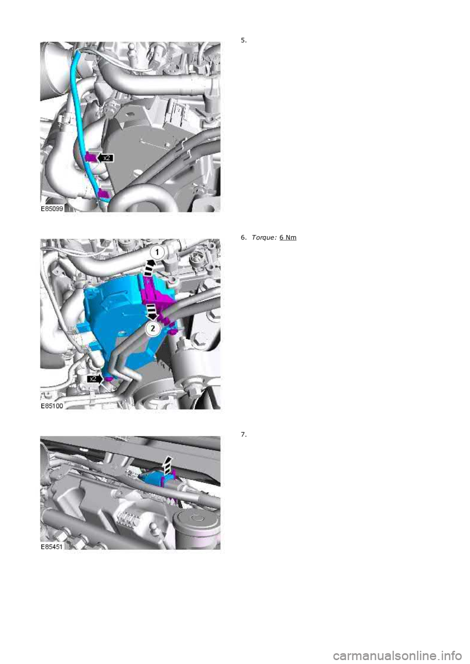
5.
T orque:
6 Nm 6.
7.
Page 1152 of 3229
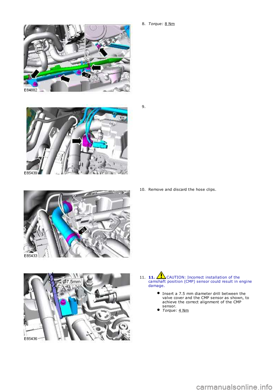
T orque:
8 Nm 8.
9.
Remove and dis card t he hos e clips .
10. 11. CAUTION: Incorrect ins tall ati on of the
cams haft posi ti on (CMP) s ens or could res ul t in engi ne
damage.
Insert a 7.5 mm diameter drill bet ween the
valve cover and t he CMP s ens or as s hown, to
achi eve the correct al ignment of the CMP
s ensor. T orque:
4 Nm 11.
Page 1153 of 3229
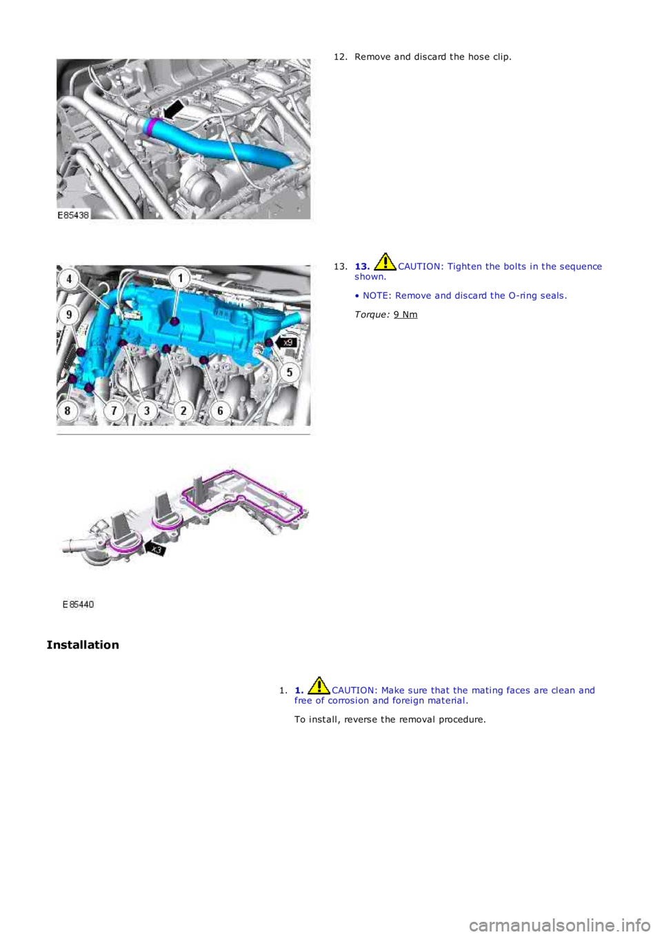
Remove and dis card t he hos e clip.
12. 13. CAUTION: Tight en the bol ts i n t he s equence
s hown.
• NOTE: Remove and dis card t he O-ri ng s eal s .
T orque: 9 Nm 13.
Installation 1. CAUTION: Make s ure that the mati ng faces are cl ean and
free of corros i on and forei gn mat erial .
To i nst all , revers e t he removal procedure.
1.
Page 1154 of 3229

Publi s hed: 11-May-2011
Intake Air Distribution and Filtering - I6 3.2L Petrol -
Torque SpecificationsDescriptionNmlb-ft
Air cl eaner hous i ng bol ts64
Page 1155 of 3229
Publi s hed: 11-May-2011
Intake Air Distribution and Filtering - I6 3.2L Petrol - Intake Air
Distribution and Filtering
Des cript ion and Operat ion
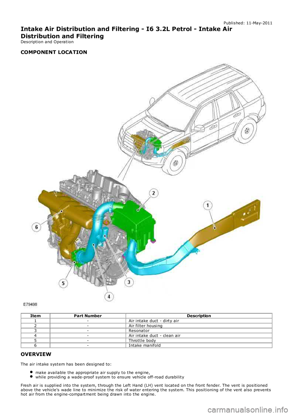
COMPONENT LOCATION
ItemPart NumberDescription
1-Air i ntake duct - dirt y ai r
2-Air fil ter housi ng3-Res onat or
4-Air i ntake duct - cl ean air
5-Throt tl e body6-Intake manifold
OVERVIEW
The air i nt ake s ys t em has been des igned to:
make available the appropriat e air s uppl y t o t he engi ne,whil e providi ng a wade-proof s ys tem to ens ure vehi cl e off-road durabil it y
Fres h air i s s uppl ied i nto t he s yst em, t hrough the Left Hand (LH) vent locat ed on t he front fender. The vent is pos it ionedabove the vehicle's wade li ne to mini mize t he ris k of water entering t he s yst em. This pos it ioning of t he vent al so prevent shot air from the engine-compart ment being drawn int o t he engi ne.
Page 1156 of 3229
A polyfibre porous duct provi di ng low int ake noi se, di rects ai r into the bas e of t he ri gid i njecti on-molded ai r fi lt er hous ing.The fi lt er hous ing is s upported on 4 elas tomer mount ings t o mi ni mi ze noi se transmis si on t o t he vehi cl e's body s truct ure. Aone-way drai n valve, incorporat ed in t he bas e of the fil ter hous ing, releas es any water t hat may have ent ered t he s yst em.Int ake air i s cl eaned as it pas ses t hrough an oi l-soaked fi lt er el ement which offers minimal obs truct ion to t he flow of ai r.
Clean ai r pas s es through the Mas s Ai r Fl ow (MAF) sens or and al ong a s ealed polypropylene duct to t he t hrot tl e body andint ake manifol d. The cl ean air duct features a s ingle quart er-wave res onator t ube to enhance engi ne sound quali ty duringint ake manifol d t ract s wit chi ng event s.
Computat ional flui d dynami cs were ext ens i vel y used in t he desi gn and refinement of the sys tem t o mi ni mize ai r-pres s uredrop.
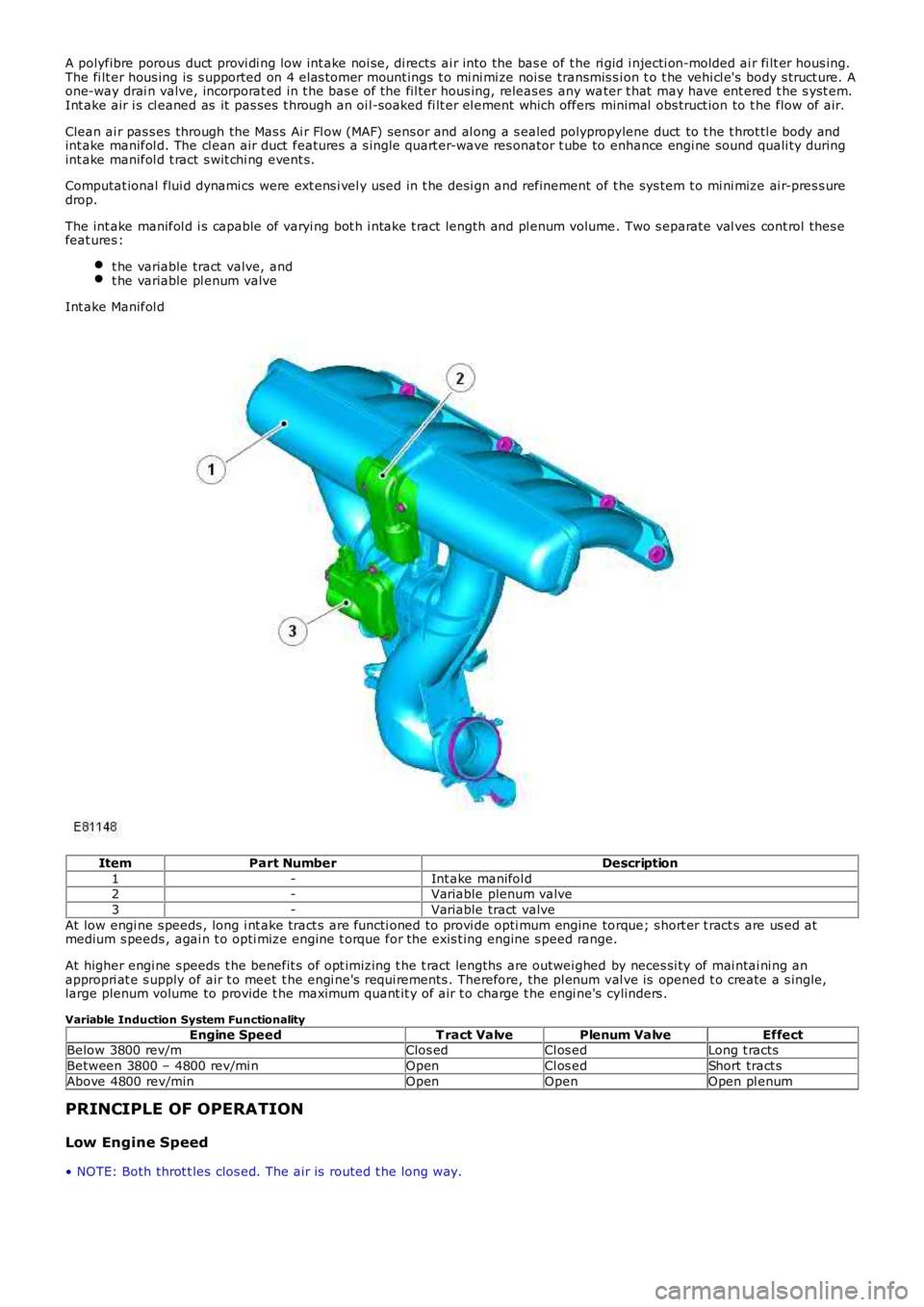
The int ake manifol d i s capable of varyi ng bot h i ntake t ract length and pl enum volume. Two s eparate val ves cont rol thes efeat ures :
t he variable tract valve, andt he variable pl enum valve
Int ake Manifol d
ItemPart NumberDescription
1-Int ake manifol d2-Variable plenum valve
3-Variable tract valve
At low engi ne s peeds , long i nt ake tract s are functi oned to provi de opti mum engine torque; s hort er t ract s are us ed atmedium s peeds , agai n t o opti mize engine t orque for the exis t ing engine s peed range.
At higher engi ne s peeds t he benefit s of opt imizing t he t ract lengths are outwei ghed by neces si ty of mai ntai ni ng anappropri at e s upply of air t o meet t he engi ne's requi rements . Therefore, the pl enum val ve is opened t o create a s ingle,large plenum volume to provide t he maximum quant it y of air t o charge t he engi ne's cylinders .
Variable Induction System Functionality
Engine SpeedT ract ValvePlenum ValveEffectBelow 3800 rev/mClos edCl os edLong t racts
Between 3800 – 4800 rev/mi nOpenCl os edShort tract s
Above 4800 rev/minOpenOpenOpen pl enum
PRINCIPLE OF OPERATION
Low Engine Speed
• NOTE: Both throt t les clos ed. The ai r is routed t he long way.
Page 1157 of 3229
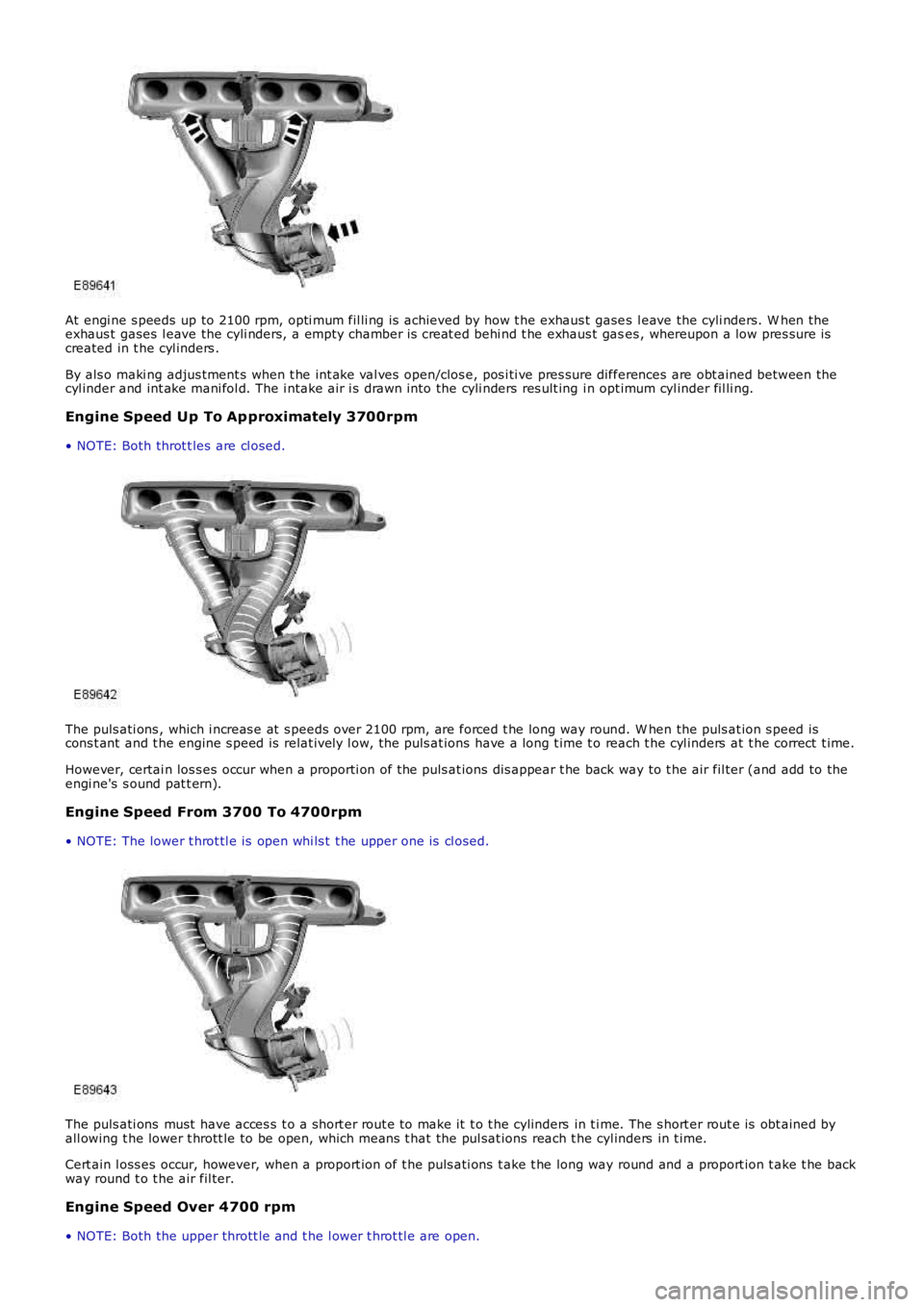
At engi ne s peeds up to 2100 rpm, opti mum fil li ng is achieved by how t he exhaus t gases l eave the cyli nders. W hen theexhaus t gases l eave the cyli nders, a empty chamber is creat ed behi nd t he exhaus t gases , whereupon a low pres sure iscreated in t he cyl inders .
By als o maki ng adjus tment s when t he int ake val ves open/clos e, pos i ti ve pres sure differences are obt ained between thecyl inder and int ake mani fol d. The i ntake air i s drawn into the cyli nders res ult ing in opt imum cyl inder fil li ng.
Engine Speed Up To Ap proximately 3700rpm
• NOTE: Both throt t les are cl osed.
The puls ati ons , which i ncreas e at s peeds over 2100 rpm, are forced t he long way round. W hen the puls at ion s peed iscons t ant and t he engine s peed is relat ively l ow, the puls at ions have a long t ime t o reach t he cyl inders at t he correct t ime.
However, certai n los s es occur when a proporti on of the puls at ions dis appear t he back way to t he air fil ter (and add to theengi ne's s ound pat t ern).
Engine Speed From 3700 To 4700rpm
• NOTE: The lower t hrot tl e is open whi ls t t he upper one is cl osed.
The puls ati ons must have acces s t o a s hort er rout e to make it t o t he cylinders in t ime. The s hort er rout e is obt ained byall owing t he lower t hrott le to be open, which means t hat the pul sat ions reach t he cyl inders in t ime.
Cert ain l oss es occur, however, when a proport ion of t he puls ati ons t ake t he long way round and a proport ion t ake t he backway round t o t he air fil ter.
Engine Speed Over 4700 rpm
• NOTE: Both the upper thrott le and t he l ower t hrot tl e are open.
Page 1158 of 3229
In thi s posi ti on, t he puls ati ons are onl y det ermined by t he s hort int ake pi pe's geometry.
The t ot al vol ume for al l cyli nders now acces s ibl e is necess ary to have s uffici ent acces s t o air.
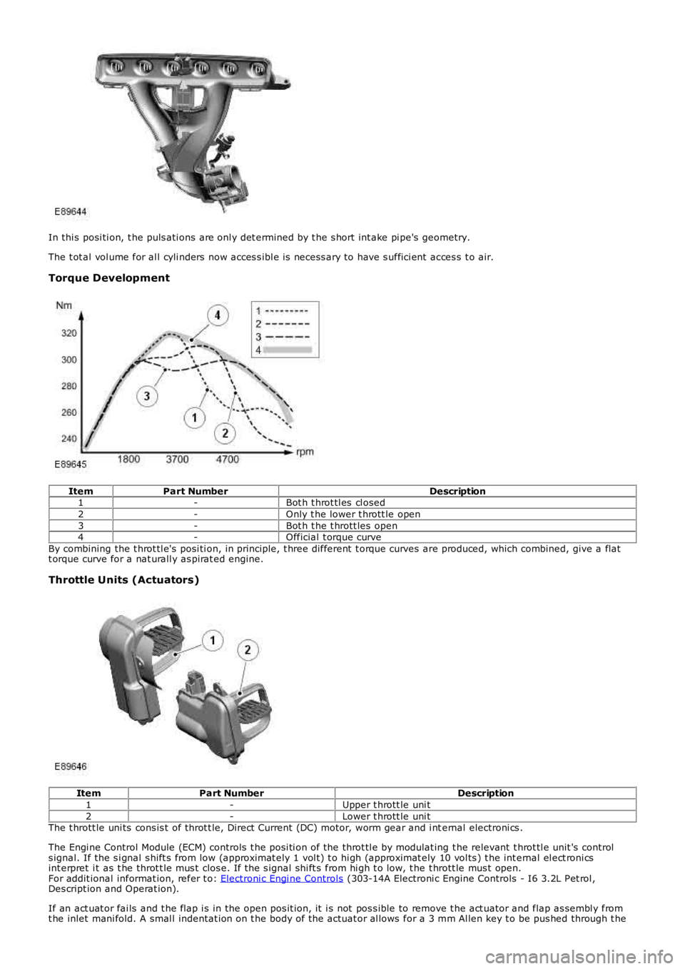
Torque Development
ItemPart NumberDescription1-Bot h t hrot tl es cl osed
2-Only t he lower t hrott le open
3-Bot h t he t hrott les open4-Official t orque curve
By combining the t hrot tl e's posi ti on, in principle, t hree different t orque curves are produced, which combined, give a flatt orque curve for a nat urall y as pirat ed engine.
Throttle Units (Actuators)
ItemPart NumberDescription
1-Upper t hrott le uni t
2-Lower t hrott le uni tThe t hrott le uni ts cons is t of throt t le, Direct Current (DC) motor, worm gear and i nternal electroni cs .
The Engi ne Control Module (ECM) controls t he posi ti on of the throt tl e by modulat ing t he relevant t hrot tl e unit 's controls ignal. If the s i gnal s hift s from low (approximat ely 1 vol t) t o hi gh (approximat ely 10 vol ts ) t he int ernal el ect roni csint erpret i t as t he throt t le mus t clos e. If t he s ignal shi ft s from hi gh t o low, t he t hrott le mus t open.For addit ional informat ion, refer t o: Electroni c Engi ne Controls (303-14A Electroni c Engine Controls - I6 3.2L Pet rol ,Des cript ion and Operat ion).
If an act uat or fai ls and t he flap i s in the open pos it ion, it i s not pos s ible to remove t he act uator and flap as sembl y fromt he inlet mani fold. A smal l indentat ion on t he body of the actuat or al lows for a 3 mm Al len key t o be pus hed through t he
Page 1159 of 3229

t hi n membrane wall of the act uat or hous ing. The All en key can be engaged i n t he spi ndl e of t he act uat or mot or, whichall ows the flap to be turned to the clos ed pos it ion and cons equent ly the actuat or and flap as s embly can t hen be removedfrom the i ntake manifold.
Page 1160 of 3229
Publi s hed: 11-May-2011
Intake Air Distribution and Filtering - I6 3.2L Petrol - Intake Air
Distribution and Filtering
Diagnosi s and Tes ti ng
Principles of Operation
For a detail ed descripti on of the intake ai r di s tributi on and fi lt eri ng sys t em, refe r t o t he rel evant Des cript ion and Operat ion
s ect ion i n t he works hop manual .
REFER to: Intake Air Di s tributi on and Fil teri ng (303-12A Int ake Air Dis t ri but ion and Fi lt ering - I6 3.2L Petrol, Des cript ion
and Operat ion).
Inspection and Verification CAUTION: Di agnos is by s ubs ti tut ion from a donor vehicle is
NO T acceptabl e. Subs ti tut ion of cont rol modules does
not guarant ee confirmat ion of a faul t, and may als o caus e addit ional fault s i n t he v ehi cl e being t est ed and/or t he donor
vehi cl e.
1. Verify t he cus t omer concern.
1.
2. Vis ually ins pect for obvious s igns of mechani cal or electrical damage.
2.
Visual Inspection Mechanical Electrical
Hos es and duct s (damage/connect ions ) Air cl eaner element (contaminated/bl ocked)
Res tricted ai r int ake
Seals and gas ket s Mass Air Flow (MAF) s ens or
Thrott le body
Harness (s ecurit y/damage)
Connecti ons (s ecurit y/damage)
3.
If an obvious cause for an obs erved or report ed concern is found, correct t he caus e (if pos s ible) before
proceeding t o t he next s t ep
3.
4. If t he caus e is not vis ually evi dent , verify t he sympt om and refer t o t he Sympt om Ch art, al ternat ively, check for
Di agnos ti c Trouble Codes (DTCs) and refer t o t he DTC Index.
4.
Symptom Chart Symptom Possible Cause Action
Vehicle does not
s tart/hard s t art ing/poor
performance Res t ri ct ed/blocked air int ake Res t ri ct ed/blocked air cleaner
el ement Ensure t he air int ake s ys t em i s free from
blockage and i s correct ly i nst all ed Ins t all a new ai r cl eaner element as
neces s ary.
REFER to: Ai r Cl eaner (303-12A Int ake Air
Dis t ri but ion and Fi lt ering - I6 3.2L Petrol,
Removal and Inst all ati on). Exces s ive i nt ake nois e
Int ake pi pe
di s connect ed/damaged aft er the
ai r cl eaner Ai r cleaner as s embly i ncorrect ly
as s embled/damaged Check for correct ins tal lat ion and i nt egri ty of
air i nt ake s ys t em Check for correct ins tal lat ion and i nt egri ty of
t he air cleaner as s embly.
REFER to: Ai r Cl eaner (303-12A Int ake Air
Dis t ri but ion and Fi lt ering - I6 3.2L Petrol,
Removal and Inst all ati on). DTC Index
• NOTE: If the control modul e or a component i s s us pect and the vehicle remains unde r manufacturer warrant y, refer t o the
W arranty Pol icy and Procedures manual (s ect ion B1.2), or determine i f any pri or appr oval programme is in operat ion, pri or
t o the ins tall ati on of a new module/component.
• NOTE: Generic scan t ool s may not read the codes li st ed, or may read only fi ve digi t codes . Mat ch the five di git s from t he
s can tool to the firs t fi ve di git s of the seven digi t code l is ted to ident ify t he fa ul t (t he las t t wo digi ts gi ve addi ti onal
informat ion read by the manufact urer approved diagnos t ic s ys tem).
• NOTE: W hen performing volt age or res is t ance t est s , always use a digi tal mult imeter (DMM) accurat e t o t hree deci mal
places, and wi th an up-t o-date cal ibrat ion cert ificate. W hen tes ti ng res is t ance al wa ys take t he res is t ance of t he DMM
leads i nt o account .
• NOTE: Check and recti fy bas ic faul ts before beginni ng diagnos t ic rout ines i nvol vi n g pinpoint t es t s.
• NOTE: Ins pect connect ors for s igns of water ingres s , and pins for damage and/or co rros ion.
• NOTE: If DTCs are recorded and, aft er performi ng the pi npoi nt tes ts , a fault is no t present , an int ermi tt ent concern may
be t he caus e. Always check for loose connect ions and corroded terminals .
DT C Description Possible Causes Action
P010100 Mas s or volume ai r fl ow A
circui t range/performance Mas s ai r fl ow (MAF) s ens or
ci rcuit : short ci rcuit t o ground Mas s ai r fl ow (MAF) s ens or Check t he MAF s ensor and circui ts . Refer t o t he
electrical gui des . Ins t all a new s ens or as
required.