LAND ROVER FRELANDER 2 2006 Repair Manual
Manufacturer: LAND ROVER, Model Year: 2006, Model line: FRELANDER 2, Model: LAND ROVER FRELANDER 2 2006Pages: 3229, PDF Size: 78.5 MB
Page 1161 of 3229
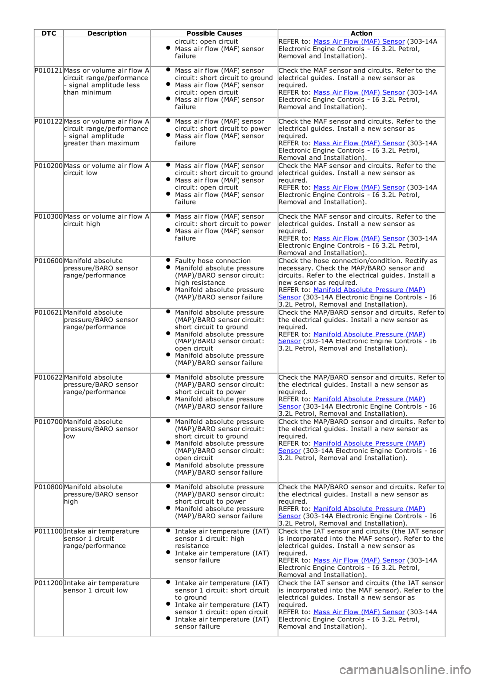
DT C
Description Possible Causes Action
ci rcuit : open ci rcuit
Mas s ai r fl ow (MAF) s ens or
fail ure REFER to:
Mas s Air Flow (MAF) Sens or (303-14A
Electroni c Engi ne Control s - I6 3.2L Pet rol ,
Removal and Inst all at ion).
P010121 Mas s or volume ai r fl ow A
circui t range/performance
- s ignal ampli tude l es s
t han mini mum Mas s ai r fl ow (MAF) s ens or
ci rcuit : short ci rcuit t o ground Mas s ai r fl ow (MAF) s ens or
ci rcuit : open ci rcuit Mas s ai r fl ow (MAF) s ens or
fail ure Check t he MAF s ensor and circui ts . Refer t o t he
electrical gui des . Ins t all a new s ens or as
required.
REFER to: Mas s Air Flow (MAF) Sens or (303-14A
Electroni c Engi ne Control s - I6 3.2L Pet rol ,
Removal and Inst all at ion).
P010122 Mas s or volume ai r fl ow A
circui t range/performance
- s ignal ampli tude
great er than maximum Mas s ai r fl ow (MAF) s ens or
ci rcuit : short ci rcuit t o power Mas s ai r fl ow (MAF) s ens or
fail ure Check t he MAF s ensor and circui ts . Refer t o t he
electrical gui des . Ins t all a new s ens or as
required.
REFER to: Mas s Air Flow (MAF) Sens or (303-14A
Electroni c Engi ne Control s - I6 3.2L Pet rol ,
Removal and Inst all at ion).
P010200 Mas s or volume ai r fl ow A
circui t low Mas s ai r fl ow (MAF) s ens or
ci rcuit : short ci rcuit t o ground Mas s ai r fl ow (MAF) s ens or
ci rcuit : open ci rcuit Mas s ai r fl ow (MAF) s ens or
fail ure Check t he MAF s ensor and circui ts . Refer t o t he
electrical gui des . Ins t all a new s ens or as
required.
REFER to: Mas s Air Flow (MAF) Sens or (303-14A
Electroni c Engi ne Control s - I6 3.2L Pet rol ,
Removal and Inst all at ion).
P010300 Mas s or volume ai r fl ow A
circui t high Mas s ai r fl ow (MAF) s ens or
ci rcuit : short ci rcuit t o power Mas s ai r fl ow (MAF) s ens or
fail ure Check t he MAF s ensor and circui ts . Refer t o t he
electrical gui des . Ins t all a new s ens or as
required.
REFER to: Mas s Air Flow (MAF) Sens or (303-14A
Electroni c Engi ne Control s - I6 3.2L Pet rol ,
Removal and Inst all at ion).
P010600 Manifold abs olut e
pres s ure/BARO s ens or
range/performance Fault y hos e connecti on Mani fold abs olut e pres s ure
(MAP)/BARO s ens or circui t:
hi gh res is t ance Mani fold abs olut e pres s ure
(MAP)/BARO s ens or fail ure Check t he hose connect ion/condit ion. Rect ify as
neces sary. Check t he MAP/BARO sens or and
ci rcuit s . Refer to the el ect ri cal guides . Ins tal l a
new s ens or as requi red.
REFER to: Manifold Abs olute Pres sure (MAP) Sens or (303-14A El ect roni c Engi ne Cont rol s - I6
3.2L Petrol, Removal and Ins tal lati on).
P010621 Manifold abs olut e
pres s ure/BARO s ens or
range/performance Mani fold abs olut e pres s ure
(MAP)/BARO s ens or circui t:
s hort ci rcuit t o ground Mani fold abs olut e pres s ure
(MAP)/BARO s ens or circui t:
open circui t Mani fold abs olut e pres s ure
(MAP)/BARO s ens or fail ure Check t he MAP/BARO s ens or and ci rcuit s . Refer to
the el ect ri cal guides . Ins tal l a new s ensor as
required.
REFER to: Manifold Abs olute Pres sure (MAP) Sens or (303-14A El ect roni c Engi ne Cont rol s - I6
3.2L Petrol, Removal and Ins tal lati on).
P010622 Manifold abs olut e
pres s ure/BARO s ens or
range/performance Mani fold abs olut e pres s ure
(MAP)/BARO s ens or circui t:
s hort ci rcuit t o power Mani fold abs olut e pres s ure
(MAP)/BARO s ens or fail ure Check t he MAP/BARO s ens or and ci rcuit s . Refer to
the el ect ri cal guides . Ins tal l a new s ensor as
required.
REFER to: Manifold Abs olute Pres sure (MAP) Sens or (303-14A El ect roni c Engi ne Cont rol s - I6
3.2L Petrol, Removal and Ins tal lati on).
P010700 Manifold abs olut e
pres s ure/BARO s ens or
l ow Mani fold abs olut e pres s ure
(MAP)/BARO s ens or circui t:
s hort ci rcuit t o ground Mani fold abs olut e pres s ure
(MAP)/BARO s ens or circui t:
open circui t Mani fold abs olut e pres s ure
(MAP)/BARO s ens or fail ure Check t he MAP/BARO s ens or and ci rcuit s . Refer to
the el ect ri cal guides . Ins tal l a new s ensor as
required.
REFER to: Manifold Abs olute Pres sure (MAP) Sens or (303-14A El ect roni c Engi ne Cont rol s - I6
3.2L Petrol, Removal and Ins tal lati on).
P010800 Manifold abs olut e
pres s ure/BARO s ens or
high Mani fold abs olut e pres s ure
(MAP)/BARO s ens or circui t:
s hort ci rcuit t o power Mani fold abs olut e pres s ure
(MAP)/BARO s ens or fail ure Check t he MAP/BARO s ens or and ci rcuit s . Refer to
the el ect ri cal guides . Ins tal l a new s ensor as
required.
REFER to: Manifold Abs olute Pres sure (MAP) Sens or (303-14A El ect roni c Engi ne Cont rol s - I6
3.2L Petrol, Removal and Ins tal lati on).
P011100 Intake air t emperat ure
s ensor 1 ci rcuit
range/performance Intake ai r temperat ure (IAT)
s ens or 1 ci rcuit : high
res is tance Intake ai r temperat ure (IAT)
s ens or fail ure Check t he IAT s ens or and circuit s (the IAT s ens or
is i ncorporated i nto the MAF sens or). Refer to the
electrical gui des . Ins t all a new s ens or as
required.
REFER to: Mas s Air Flow (MAF) Sens or (303-14A
Electroni c Engi ne Control s - I6 3.2L Pet rol ,
Removal and Inst all at ion).
P011200 Intake air t emperat ure
s ensor 1 ci rcuit l ow Intake ai r temperat ure (IAT)
s ens or 1 ci rcuit : s hort circuit
t o ground Intake ai r temperat ure (IAT)
s ens or 1 ci rcuit : open ci rcuit Intake ai r temperat ure (IAT)
s ens or fail ure Check t he IAT s ens or and circuit s (the IAT s ens or
is i ncorporated i nto the MAF sens or). Refer to the
electrical gui des . Ins t all a new s ens or as
required.
REFER to: Mas s Air Flow (MAF) Sens or (303-14A
Electroni c Engi ne Control s - I6 3.2L Pet rol ,
Removal and Inst all at ion).
Page 1162 of 3229
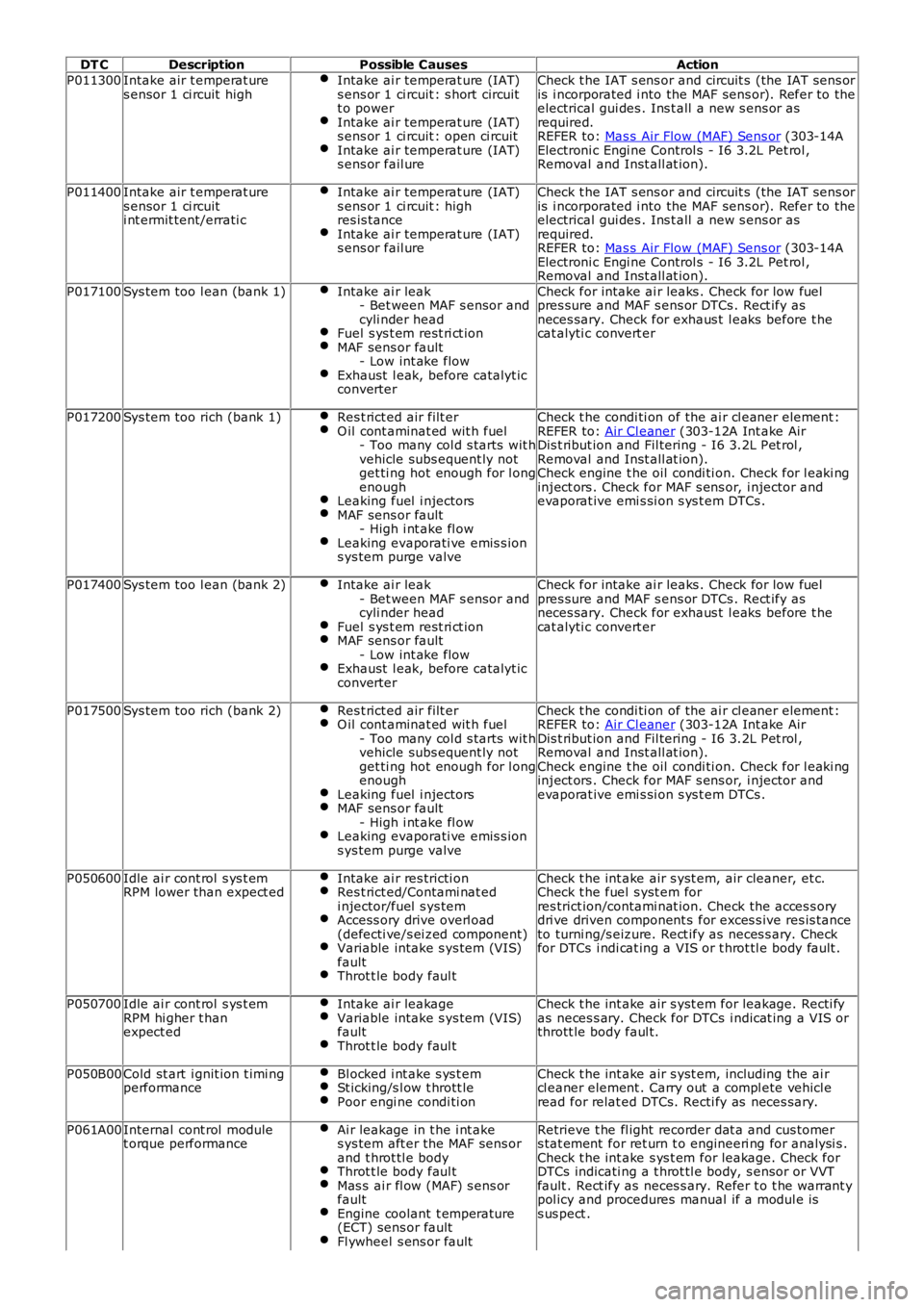
DT C
Description Possible Causes Action
P011300 Intake air t emperat ure
s ensor 1 ci rcuit high Intake ai r temperat ure (IAT)
s ens or 1 ci rcuit : s hort circuit
t o power Intake ai r temperat ure (IAT)
s ens or 1 ci rcuit : open ci rcuit Intake ai r temperat ure (IAT)
s ens or fail ure Check t he IAT s ens or and circuit s (the IAT s ens or
is i ncorporated i nto the MAF sens or). Refer to the
electrical gui des . Ins t all a new s ens or as
required.
REFER to: Mas s Air Flow (MAF) Sens or (303-14A
Electroni c Engi ne Control s - I6 3.2L Pet rol ,
Removal and Inst all at ion).
P011400 Intake air t emperat ure
s ensor 1 ci rcuit
i nt ermit tent/errati c Intake ai r temperat ure (IAT)
s ens or 1 ci rcuit : high
res is tance Intake ai r temperat ure (IAT)
s ens or fail ure Check t he IAT s ens or and circuit s (the IAT s ens or
is i ncorporated i nto the MAF sens or). Refer to the
electrical gui des . Ins t all a new s ens or as
required.
REFER to: Mas s Air Flow (MAF) Sens or (303-14A
Electroni c Engi ne Control s - I6 3.2L Pet rol ,
Removal and Inst all at ion).
P017100 Sys tem too l ean (bank 1) Intake ai r leak
- Bet ween MAF s ensor and
cyli nder head Fuel s ys t em rest ri ct ion
MAF sens or fault
- Low int ake flow Exhaust l eak, before catalyt ic
converter Check for intake ai r leaks . Check for low fuel
pres sure and MAF s ens or DTCs . Rect ify as
neces sary. Check for exhaus t l eaks before t he
cat alyti c convert er
P017200 Sys tem too rich (bank 1) Res t rict ed air filt er O il cont aminat ed wit h fuel
- Too many col d s tarts wit h
vehicle subs equent ly not
get ti ng hot enough for l ong
enough Leaking fuel i njectors
MAF sens or fault
- High i nt ake fl ow Leaking evaporati ve emis s ion
s ys tem purge valve Check t he condi ti on of the ai r cl eaner element :
REFER to: Air Cl eaner (303-12A Int ake Air
Dis t ribut ion and Fil tering - I6 3.2L Pet rol ,
Removal and Inst all at ion).
Check engine t he oil condi ti on. Check for l eaki ng
inject ors . Check for MAF s ens or, i njector and
evaporat ive emi s si on s ys t em DTCs .
P017400 Sys tem too l ean (bank 2) Intake ai r leak
- Bet ween MAF s ensor and
cyli nder head Fuel s ys t em rest ri ct ion
MAF sens or fault
- Low int ake flow Exhaust l eak, before catalyt ic
converter Check for intake ai r leaks . Check for low fuel
pres sure and MAF s ens or DTCs . Rect ify as
neces sary. Check for exhaus t l eaks before t he
cat alyti c convert er
P017500 Sys tem too rich (bank 2) Res t rict ed air filt er O il cont aminat ed wit h fuel
- Too many col d s tarts wit h
vehicle subs equent ly not
get ti ng hot enough for l ong
enough Leaking fuel i njectors
MAF sens or fault
- High i nt ake fl ow Leaking evaporati ve emis s ion
s ys tem purge valve Check t he condi ti on of the ai r cl eaner element :
REFER to: Air Cl eaner (303-12A Int ake Air
Dis t ribut ion and Fil tering - I6 3.2L Pet rol ,
Removal and Inst all at ion).
Check engine t he oil condi ti on. Check for l eaki ng
inject ors . Check for MAF s ens or, i njector and
evaporat ive emi s si on s ys t em DTCs .
P050600 Idle ai r cont rol s ys t em
RPM lower than expect ed Intake ai r res tricti on Res t rict ed/Contami nat ed
i njector/fuel s ys tem Access ory drive overl oad
(defecti ve/s ei zed component) Variable intake s ys tem (VIS)
fault Throt t le body faul t Check t he int ake air s yst em, air cleaner, et c.
Check t he fuel s yst em for
res trict ion/contami nat ion. Check the acces s ory
dri ve driven component s for exces s ive res is tance
to turni ng/s eizure. Rect ify as neces s ary. Check
for DTCs i ndi cat ing a VIS or t hrot tl e body fault .
P050700 Idle ai r cont rol s ys t em
RPM hi gher t han
expect ed Intake ai r leakage Variable intake s ys tem (VIS)
fault Throt t le body faul t Check t he int ake air s yst em for leakage. Recti fy
as neces s ary. Check for DTCs i ndicat ing a VIS or
thrott le body faul t.
P050B00 Cold st art i gnit ion t imi ng
performance Bl ocked i nt ake s ys t em St icking/s l ow t hrott le
Poor engi ne condi ti on Check t he int ake air s yst em, including the ai r
cl eaner element . Carry out a compl ete vehicl e
read for relat ed DTCs. Recti fy as neces sary.
P061A00 Internal cont rol module
t orque performance Ai r leakage in t he i nt ake
s ys tem aft er the MAF sens or
and t hrot tl e body Throt t le body faul t
Mas s ai r fl ow (MAF) s ens or
fault Engine coolant t emperature
(ECT) sens or fault Fl ywheel s ens or fault Retrieve t he fl ight recorder dat a and cus tomer
s tat ement for ret urn t o engineeri ng for analysi s .
Check t he int ake s ys t em for leakage. Check for
DTCs indicati ng a t hrot tl e body, s ensor or VVT
fault . Rect ify as neces s ary. Refer t o t he warrant y
pol icy and procedures manual if a modul e is
s us pect .
Page 1163 of 3229
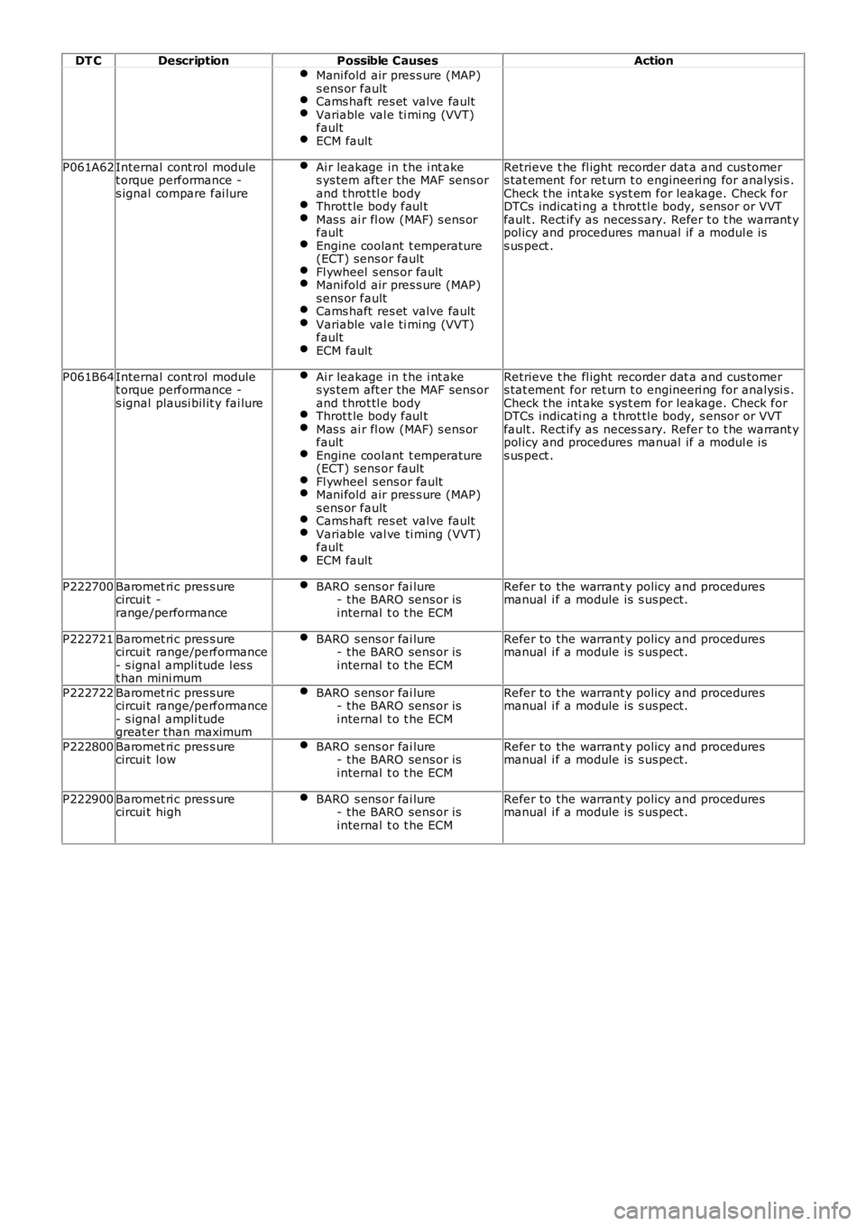
DT C
Description Possible Causes Action
Mani fold air pres s ure (MAP)
s ens or fault Cams haft res et valve fault
Variable val e ti mi ng (VVT)
fault ECM fault
P061A62
Internal cont rol module
t orque performance -
s ignal compare fai lure Ai r leakage in t he i nt ake
s ys tem aft er the MAF sens or
and t hrot tl e body Throt t le body faul t
Mas s ai r fl ow (MAF) s ens or
fault Engine coolant t emperature
(ECT) sens or fault Fl ywheel s ens or fault
Mani fold air pres s ure (MAP)
s ens or fault Cams haft res et valve fault
Variable val e ti mi ng (VVT)
fault ECM fault Retrieve t he fl ight recorder dat a and cus tomer
s tat ement for ret urn t o engineeri ng for analysi s .
Check t he int ake s ys t em for leakage. Check for
DTCs indicati ng a t hrot tl e body, s ensor or VVT
fault . Rect ify as neces s ary. Refer t o t he warrant y
pol icy and procedures manual if a modul e is
s us pect .
P061B64 Internal cont rol module
t orque performance -
s ignal plausi bil it y fai lure Ai r leakage in t he i nt ake
s ys tem aft er the MAF sens or
and t hrot tl e body Throt t le body faul t
Mas s ai r fl ow (MAF) s ens or
fault Engine coolant t emperature
(ECT) sens or fault Fl ywheel s ens or fault
Mani fold air pres s ure (MAP)
s ens or fault Cams haft res et valve fault
Variable val ve ti ming (VVT)
fault ECM fault Retrieve t he fl ight recorder dat a and cus tomer
s tat ement for ret urn t o engineeri ng for analysi s .
Check t he int ake s ys t em for leakage. Check for
DTCs indicati ng a t hrot tl e body, s ensor or VVT
fault . Rect ify as neces s ary. Refer t o t he warrant y
pol icy and procedures manual if a modul e is
s us pect .
P222700 Baromet ri c pres s ure
circui t -
range/performance BARO s ens or fai lure
- the BARO sens or is
i nternal t o t he ECM Refer to the warrant y policy and procedures
manual i f a module is s us pect.
P222721 Baromet ri c pres s ure
circui t range/performance
- s ignal ampli tude l es s
t han mini mum BARO s ens or fai lure
- the BARO sens or is
i nternal t o t he ECM Refer to the warrant y policy and procedures
manual i f a module is s us pect.
P222722 Baromet ri c pres s ure
circui t range/performance
- s ignal ampli tude
great er than maximum BARO s ens or fai lure
- the BARO sens or is
i nternal t o t he ECM Refer to the warrant y policy and procedures
manual i f a module is s us pect.
P222800 Baromet ri c pres s ure
circui t low BARO s ens or fai lure
- the BARO sens or is
i nternal t o t he ECM Refer to the warrant y policy and procedures
manual i f a module is s us pect.
P222900 Baromet ri c pres s ure
circui t high BARO s ens or fai lure
- the BARO sens or is
i nternal t o t he ECM Refer to the warrant y policy and procedures
manual i f a module is s us pect.
Page 1164 of 3229
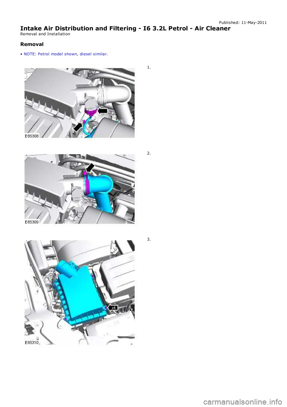
Publi s hed: 11-May-2011
Intake Air Distribution and Filtering - I6 3.2L Petrol - Air Cleaner
Removal and Inst all ati on
Removal
• NOTE: Petrol model s hown, di esel s imilar.
1.
2.
3.
Page 1165 of 3229
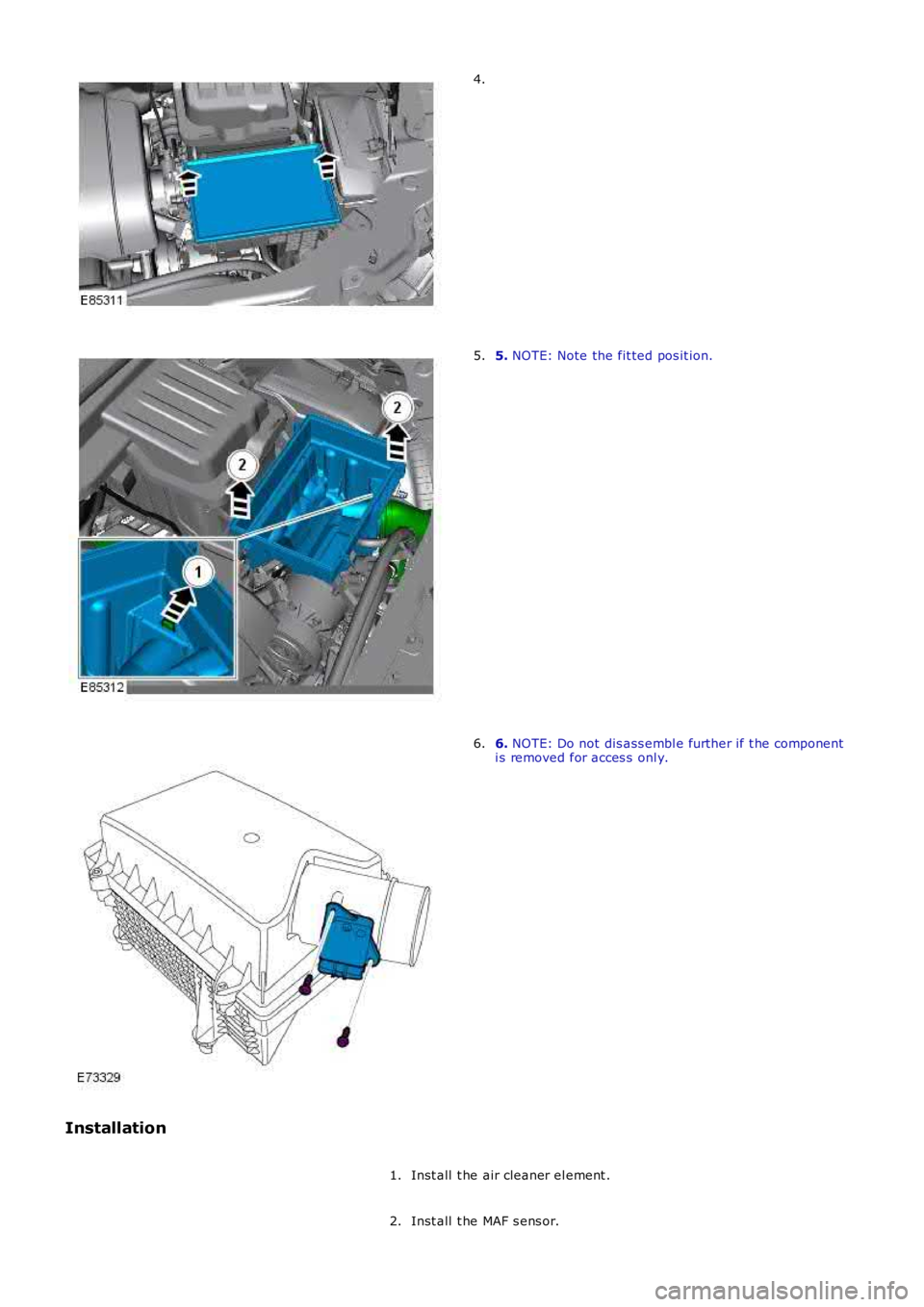
4.
5. NOTE: Note the fit ted pos it ion.5.
6. NOTE: Do not dis ass embl e further if t he componenti s removed for acces s onl y.6.
Installation
Inst all t he air cleaner el ement .1.
Inst all t he MAF s ens or.2.
Page 1166 of 3229

3. NOTE: Ali gn to the pos it ion not ed on removal.
Inst all t he air cleaner hous ing.
3.
Inst all t he air cleaner out let pipes .4.
Connect t he MAF s ensor electrical connect or.5.
Page 1167 of 3229
Publi s hed: 11-May-2011
Intake Air Distribution and Filtering - TD4 2.2L Diesel -
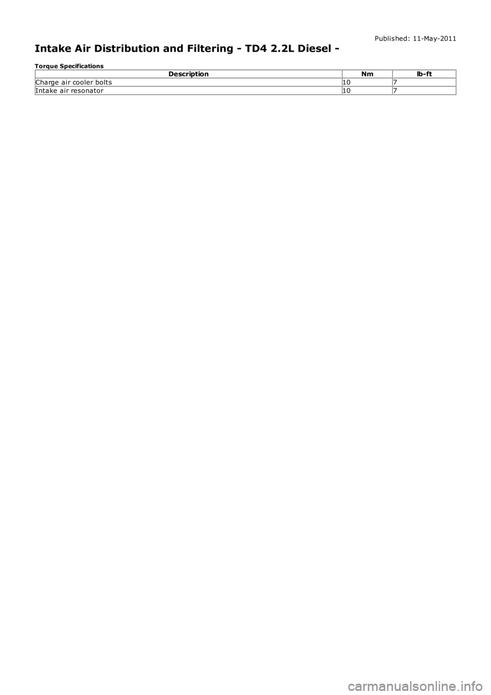
Torque SpecificationsDescriptionNmlb-ft
Charge ai r cooler bolt s107
Intake air resonator107
Page 1168 of 3229
Publi s hed: 11-May-2011
Intake Air Distribution and Filtering - TD4 2.2L Diesel - Intake Air
Distribution and Filtering
Des cript ion and Operat ion
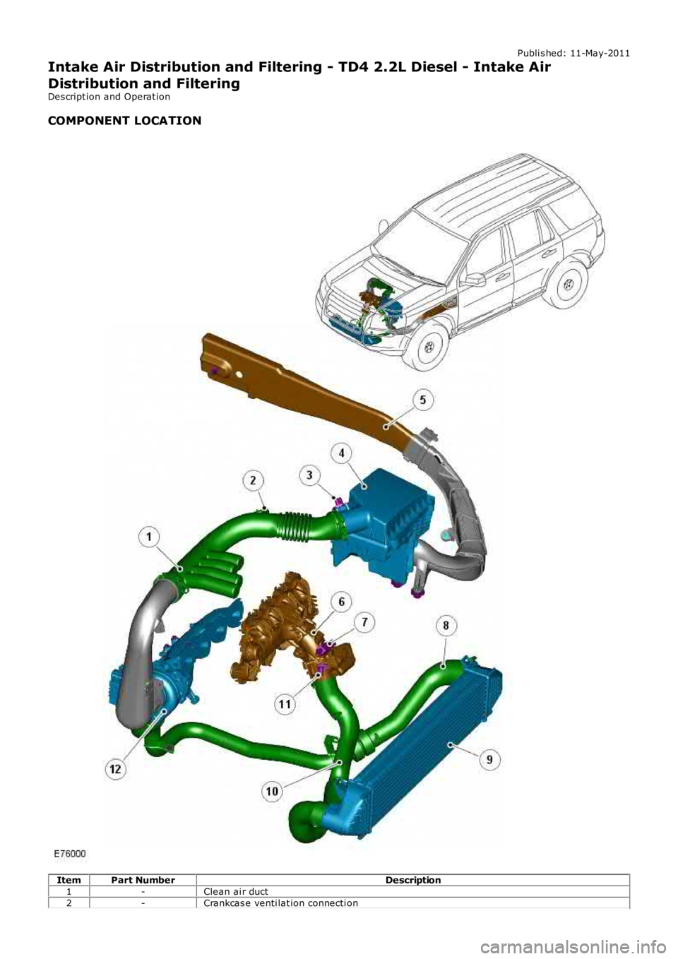
COMPONENT LOCATION
ItemPart NumberDescription
1-Clean ai r duct
2-Crankcas e venti lat ion connecti on
Page 1169 of 3229
3-Mas s Air Flow (MAF) s ensor
4-Air fil ter housi ng
5-Dirty air int ake duct6-Electroni c t hrott le and int ake mani fol d ass embl y
7-Manifol d Abs olute Pres sure (MAP) sens or
8-Hos e - t urbocharger t o charge air cooler9-Charge air cooler
10-Hos e - charge air cooler to elect roni c thrott le (3 pi ece)
11-Int ake Air Temperat ure (IAT) s ens or12-Turbocharger and exhaus t mani fold
OVERVIEW
The TD4 engine i nt ake air s yst em provides fi lt ered and pres s uri zed ai r to the engine cyli nders , to promote compl etecombus t ion of t he inject ed fuel under al l engine condit ions .
A di rt y air i nt ake duct i s located behind the Left -Hand (LH) front fender and is connect ed to the ai r fi lt er hous ing. Air isdrawn into the i ntake air duct and direct ed through an oil impregnat ed repl aceable fil ter element , locat ed wi thi n the ai rfi lt er hous ing. The filt ered i ntake air i s t hen direct ed through t he clean ai r duct t o the compress or s ide of t he turbocharger.
The clean air duct is manufact ured t o i ncorporat e 4-quarter wave t ubes and a connection to the crankcas e venti lat ions ys t em. The quarter wave t ubes reduce the Noi se, Vi brati on and Hars hnes s (NVH) levels creat ed by t he air t raveli ngt hrough the duct. The connect ion t o t he crankcas e vent il ati on s ys t em al lows environment al ly harmful gas es and vapors tobe drawn from t he engine crankcas e, and int o t he cl ean air duct . The gases and vapors are mi xed wit h t he fi lt ered i ntakeair and burned i n t he cyl inders .
The t urbocharger compres ses and di rects the press uri zed hot i ntake air t hrough a large bore connecti ng hos e to t he chargeair cooler. The ai r pas s es through the charge ai r cooler and i s s ubs equent ly cooled t o i ncreas e t he i nt ake air densi ty. Theoutput s ide of t he charge air cool er direct s the cool dens e ai r through a large bore connecti ng hose to the el ect ronict hrott le and intake mani fold, where the ai r is then dis t ri but ed via the i ntake manifold ports t o t he i ndi vi dual enginecyl inders .
Exhaus t gas via t he Exhaus t Gas Reci rculat ion (EGR) sys t em i s als o direct ed i nt o t he int ake air s yst em t o reduce Oxi des OfNit rogen (NOX) emis s ions . A pipe connect s t he EGR valve l ocat ed at the Ri ght -Hand (RH) s ide of t he engine, to the i ntakemanifold l ocat ed at the Left-Hand (LH) s ide of t he engine. The exchange of exhaust gas i nto t he i nt ake manifold i scont rol led by t he Engine Control Modul e (ECM) during cert ain engine operat ing conditions.For addit ional informat ion, refer t o: Engi ne Emis s ion Cont rol (303-08B Engi ne Emis s ion Cont rol - TD4 2.2L Di esel ,Des cript ion and Operat ion).
Electroni c s ens ors are s t rat egi cal ly l ocat ed around t he int ake ai r s ys t em and const antl y provide i nformat ion of IAT, MAFand MAP t o t he ECM. Thi s i nformat ion i s proces sed and us ed by t he ECM for adjust ing engi ne performance to meet thecurrent operat ing condi ti ons , and driver demands .For addit ional informat ion, refer t o: Electroni c Engi ne Controls - 2.2L Dies el (303-14 El ect ronic Engine Cont rols - 2.2LDies el, Des cript ion and Operat ion).
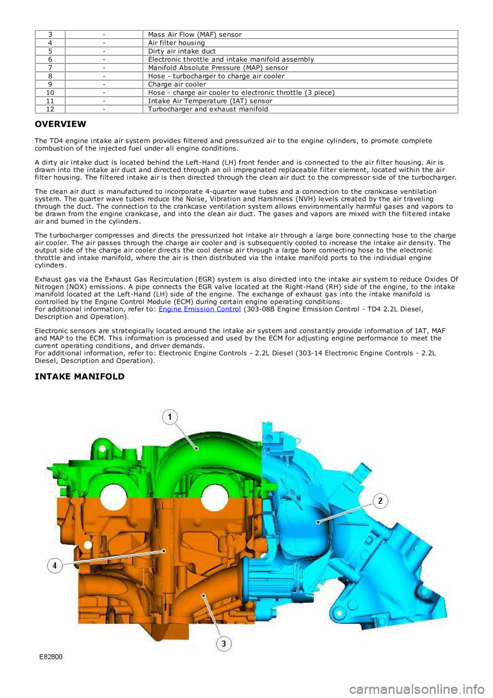
INTAKE MANIFOLD
Page 1170 of 3229
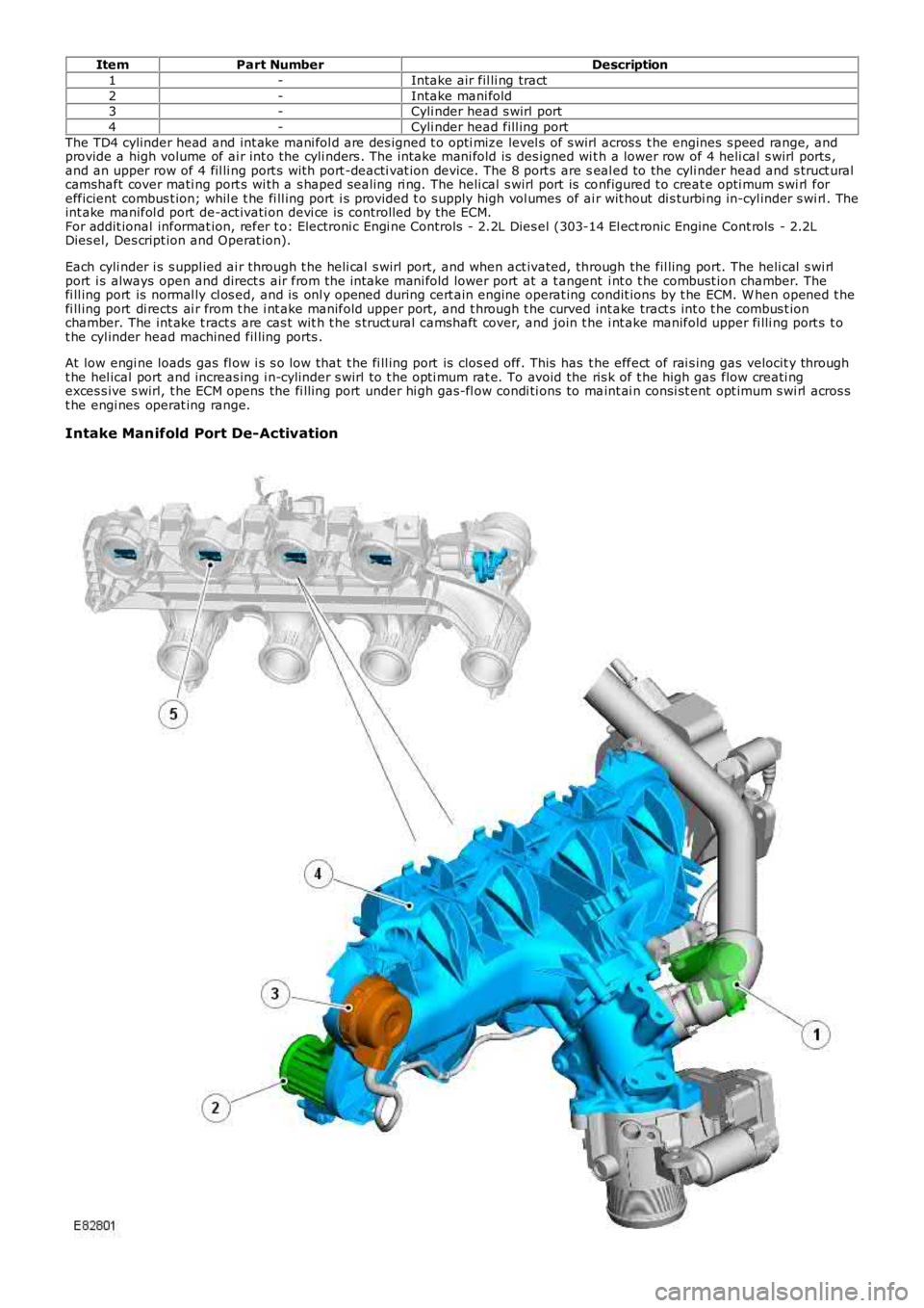
ItemPart NumberDescription
1-Intake air fil li ng tract
2-Intake mani fold3-Cyli nder head s wirl port
4-Cyli nder head fill ing port
The TD4 cylinder head and int ake mani fol d are des igned t o opti mize level s of s wirl acros s t he engines s peed range, andprovide a high volume of ai r int o the cyli nders . The intake mani fold is des igned wi th a lower row of 4 heli cal s wirl ports ,and an upper row of 4 fil li ng port s wit h port -deacti vat ion device. The 8 port s are seal ed to the cyli nder head and s truct uralcamshaft cover mati ng port s wi th a s haped s ealing ri ng. The heli cal s wirl port is configured t o creat e opti mum s wi rl forefficient combus t ion; whil e t he fi ll ing port i s provided t o s upply high vol umes of ai r wit hout di s turbi ng in-cyl inder s wi rl . Theint ake manifol d port de-act ivati on devi ce is controlled by the ECM.For addit ional informat ion, refer t o: Electroni c Engi ne Controls - 2.2L Dies el (303-14 El ect ronic Engine Cont rols - 2.2LDies el, Des cript ion and Operat ion).
Each cyli nder i s s uppl ied ai r through t he heli cal s wirl port, and when act ivated, through the fil ling port. The heli cal s wi rlport i s always open and direct s air from the intake mani fold lower port at a t angent i nt o t he combust ion chamber. Thefi ll ing port is normal ly cl os ed, and is onl y opened during cert ain engine operat ing condit ions by t he ECM. W hen opened t hefi ll ing port di rects ai r from t he i nt ake manifold upper port, and t hrough t he curved int ake tract s int o t he combus t ionchamber. The int ake t ract s are cas t wit h t he s truct ural cams haft cover, and join t he i nt ake manifold upper fi lli ng port s t ot he cyl inder head machined fil ling ports .
At low engi ne loads gas fl ow i s s o low that t he fi ll ing port is clos ed off. This has t he effect of rai s ing gas velocit y throught he hel ical port and increas ing i n-cylinder s wirl to t he opti mum rat e. To avoid the ris k of t he high gas flow creati ngexces s ive s wirl, t he ECM opens the fi lli ng port under hi gh gas-fl ow condi ti ons to maint ai n consi st ent opt imum s wi rl acros st he engi nes operat ing range.
Intake Manifold Port De-Activation