LAND ROVER FRELANDER 2 2006 Repair Manual
FRELANDER 2 2006
LAND ROVER
LAND ROVER
https://www.carmanualsonline.info/img/64/57251/w960_57251-0.png
LAND ROVER FRELANDER 2 2006 Repair Manual
Trending: mileage, auxiliary battery, timing belt, traction control, headrest, maintenance, ground clearance
Page 2261 of 3229
Suppl ement al Rest rai nt Sys tem, Des cri pti on and Operati on).
The ins t rument panel cons i st s of 2 pl as t ic mol dings (upper and lower) which are welded t oget her t o provi de a s ingleas sembl y. The i nst rument panel provi des mounti ng poi nts for various driver and pas s enger int erfaces . Als o containedwit hin the i nst rument panel are t he air dis t ri but ion ducts , vents and regis ters.For addit ional informat ion, refer t o: Air Di st ri buti on and Fi lt eri ng (412-01 Climat e Cont rol, Des cript ion and O perati on).
Page 2262 of 3229
Publi s hed: 11-May-2011
Instrument Panel and Console - Instrument PanelTD4 2.2L Diesel
Removal and Inst all ati on
Removal
Make t he SRS s ys t em s afe.
Refer t o: Supplement al Res t raint Sys tem (SRS) Depowering andRepowering (501-20, General Procedures ).
1.
Remove t he winds hield wiper motor.
Refer t o: W i nds hield W i per Mot or (501-16 W ipers and W as hers ,Removal and Ins tall ati on).
2.
Evacuate the A/C s ys tem.
Refer t o: Air Condi ti oning (A/C) Sys tem Recovery, Evacuati on andCharging (412-00 Cl imat e Control Sys t em - General Informat ion,General Procedures).
3.
Remove both front door ass embl ies .
Refer t o: Front Door (501-03 Body Clos ures , Removal andInst all at ion).
4.
Remove both A-pil lar upper t ri m panels .
Refer t o: A-Pil lar Tri m Panel (501-05 Int erior Trim andOrnament ati on, Removal and Ins tal lat ion).
5.
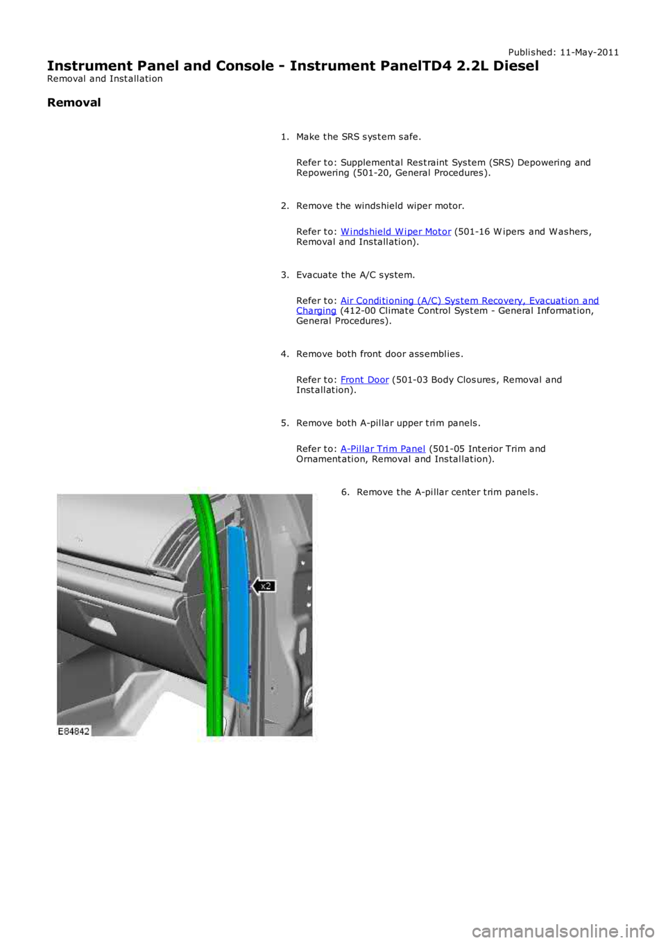
Remove t he A-pi llar center t rim panels .6.
Page 2263 of 3229
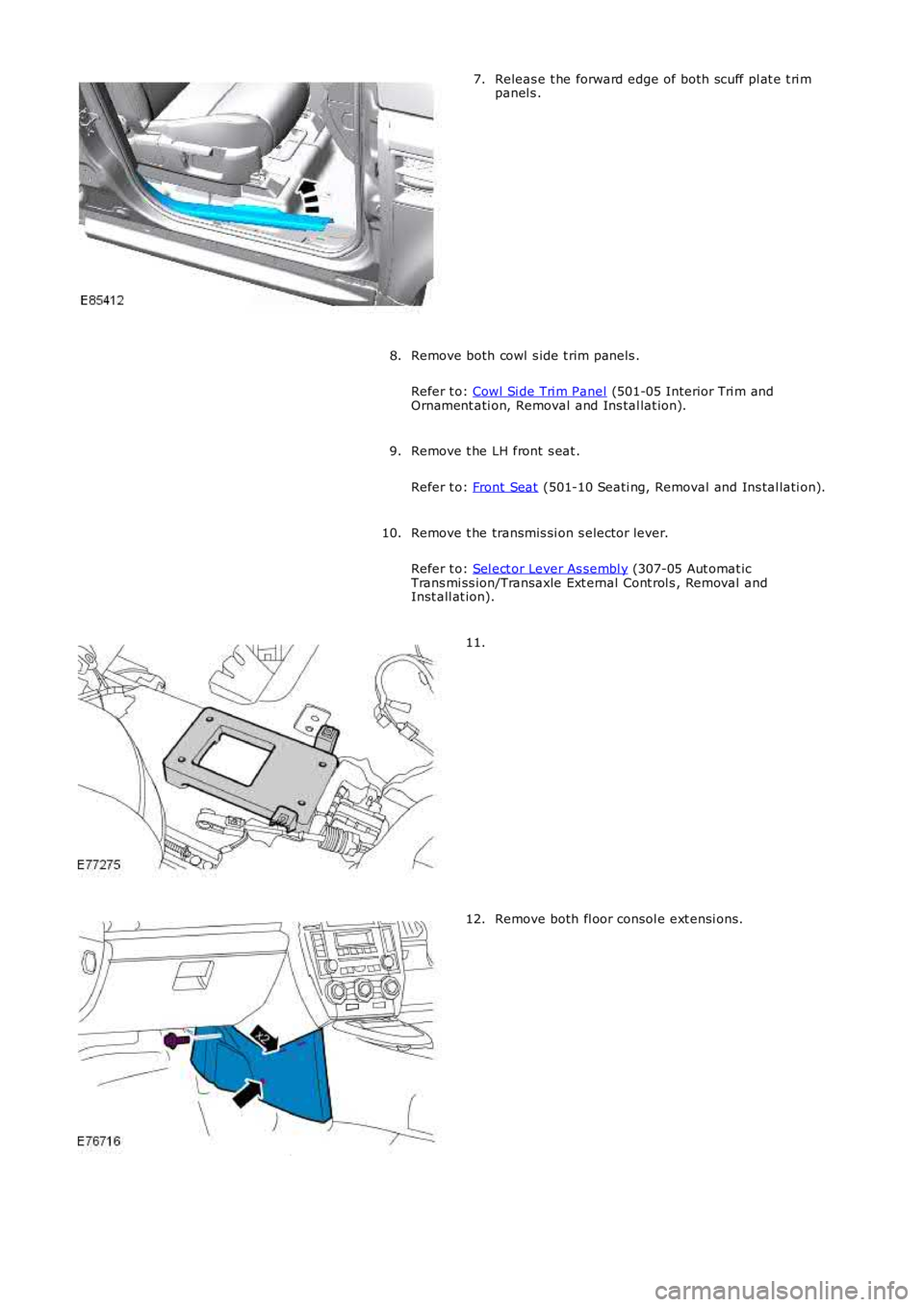
Releas e t he forward edge of both scuff pl at e t ri mpanel s .7.
Remove both cowl s ide t rim panels .
Refer t o: Cowl Si de Tri m Panel (501-05 Interior Tri m andOrnament ati on, Removal and Ins tal lat ion).
8.
Remove t he LH front s eat .
Refer t o: Front Seat (501-10 Seati ng, Removal and Ins tal lati on).
9.
Remove t he transmis si on s elector lever.
Refer t o: Sel ect or Lever As sembl y (307-05 Aut omat icTrans mi ss ion/Transaxle Ext ernal Cont rol s , Removal andInst all at ion).
10.
11.
Remove both fl oor consol e ext ensi ons.12.
Page 2264 of 3229
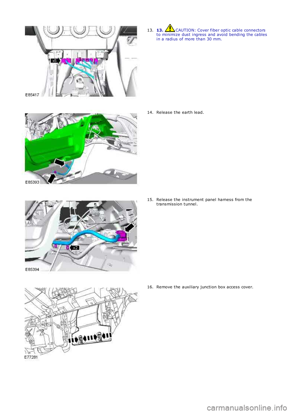
13. CAUTION: Cover fiber opti c cabl e connectorst o mi nimi ze dus t i ngress and avoid bendi ng the cablesi n a radi us of more than 30 mm.
13.
Releas e t he eart h lead.14.
Releas e t he ins trument panel harnes s from t het rans mis s ion t unnel .15.
Remove t he auxi liary juncti on box acces s cover.16.
Page 2265 of 3229
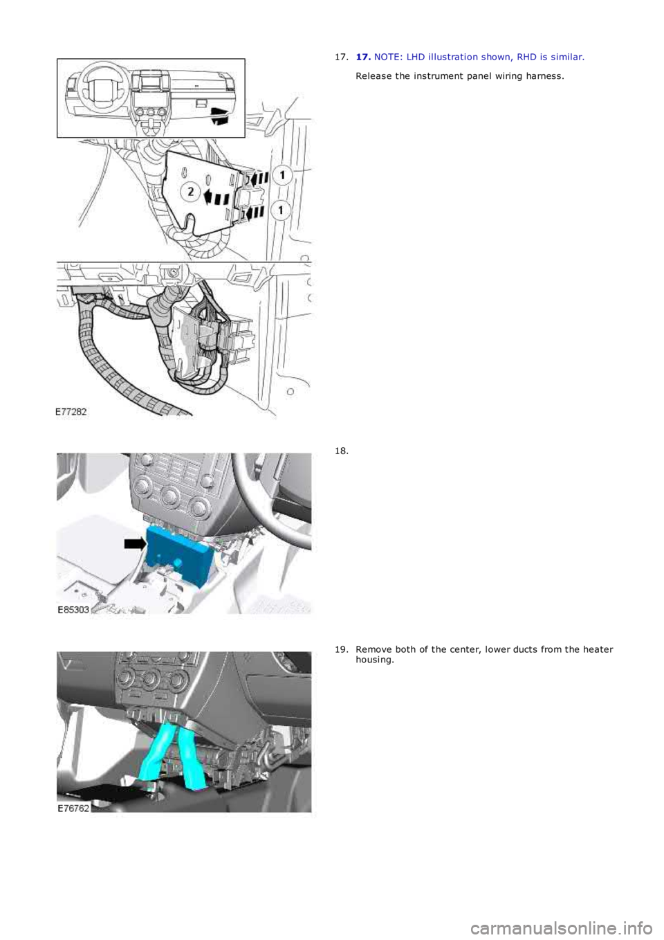
17. NOTE: LHD il lus trati on s hown, RHD is s imil ar.
Releas e t he ins trument panel wiring harnes s .
17.
18.
Remove both of t he center, l ower duct s from t he heaterhousi ng.19.
Page 2266 of 3229
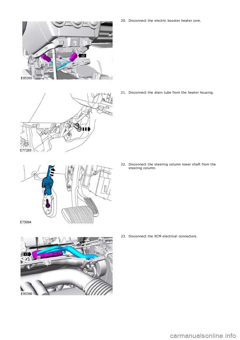
Di sconnect t he electric boost er heat er core.20.
Di sconnect t he drain tube from the heat er hous ing.21.
Di sconnect t he s teeri ng col umn l ower s haft from t hes teering column.22.
Di sconnect t he ECM electrical connect ors .23.
Page 2267 of 3229
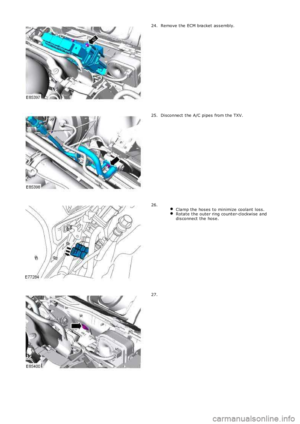
Remove t he ECM bracket as s embly.24.
Di sconnect t he A/C pipes from t he TXV.25.
Clamp the hos es t o mi nimi ze coolant l os s .Rotat e t he outer ring count er-cl ockwi se anddis connect the hos e.
26.
27.
Page 2268 of 3229
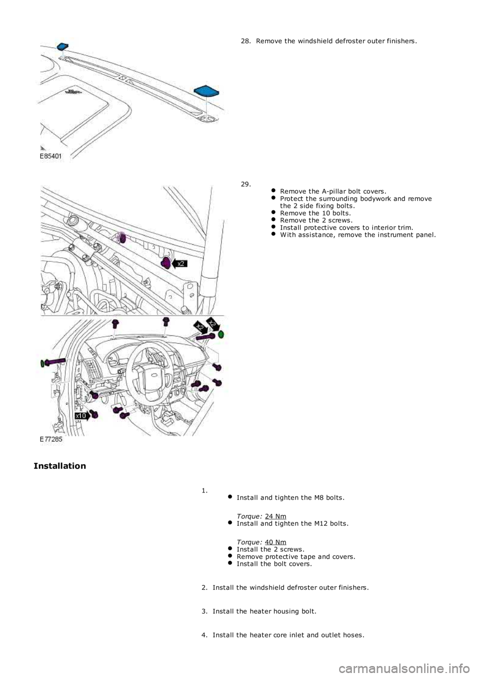
Remove t he winds hield defros ter outer finis hers .
28.
Remove t he A-pi llar bolt covers . Prot ect t he s urroundi ng bodywork and remove
t he 2 s ide fixi ng bol ts . Remove t he 10 bolt s.
Remove t he 2 s crews .
Inst all prot ect ive covers t o i nt eri or trim.
W it h ass i st ance, remove the i nst rument panel.29.
Installation Inst all and t ighten t he M8 bol ts .
T orque: 24 Nm Inst all and t ighten t he M12 bol ts .
T orque: 40 Nm Inst all t he 2 s crews .
Remove prot ect ive t ape and covers.
Inst all t he bol t covers.1.
Inst all t he winds hield defros ter outer finis hers .
2.
Inst all t he heat er hous ing bol t.
3.
Inst all t he heat er core inl et and out let hos es .
4.
Page 2269 of 3229
Remove t he cool ant hos e clamps .
5.
Connect t he A/C pipes t o the TXV and ti ght en t he M6 nut .
T orque: 10 Nm 6.
Inst all t he ECM bracket as s embly and ti ght en t he nut s .
T orque: 10 Nm 7.
Connect t he ECM elect rical connectors .
8.
9. W ARNING: Make sure t hat a new bolt i s ins tal led.
Connect t he s teeri ng col umn l ower s haft and t ight en the bol t.
T orque: 25 Nm 9.
Connect t he drain tube t o t he heater hous i ng.
10.
Connect t he electric boos ter heat er core.
11.
Inst all t he cent er, lower ducts t o t he heater hous i ng.
12.
Inst all t he NVH pad.
13.
Inst all t he ins trument panel wiring harnes s .
14.
Inst all t he auxi liary juncti on box acces s cover.
15.
Secure t he ins trument panel harnes s to the trans mi ss i on tunnel.
16.
Secure and t ighten the eart h l ead.
T orque: 10 Nm 17.
Connect t he body harnes s t o t he i ns t rument panel .
18.
Inst all t he fl oor consol e extens ions.
19.
Inst all t he s el ect or lever mount ing bracket.
20.
Inst all t he transmis si on s elector lever.
Refer t o: Sel ect or Lever As sembl y (307-05 Aut omat ic
Trans mi ss ion/Transaxle Ext ernal Cont rol s , Removal and
Inst all at ion).
21.
Inst all t he LH front s eat .
Refer t o: Front Seat (501-10 Seati ng, Removal and Ins tal lati on).
22.
Inst all both cowl s ide t rim panels .
Refer t o: Cowl Si de Tri m Panel (501-05 Interior Tri m and
Ornament ati on, Removal and Ins tal lat ion).
23.
Secure both scuff pl ate t rim panels .
24.
Inst all t he A-pi llar center t rim panels .
25.
Page 2270 of 3229
Inst all both A-pil lar upper t ri m panels .
Refer t o: A-Pil lar Tri m Panel (501-05 Int erior Trim andOrnament ati on, Removal and Ins tal lat ion).
26.
Inst all both front door ass embl ies .
Refer t o: Front Door (501-03 Body Clos ures , Removal andInst all at ion).
27.
Recharge the A/C sys tem.
Refer t o: Air Condi ti oning (A/C) Sys tem Recovery, Evacuati on andCharging (412-00 Cl imat e Control Sys t em - General Informat ion,General Procedures).
28.
Inst all t he winds hield wiper motor.
Refer t o: W i nds hield W i per Mot or (501-16 W ipers and W as hers ,Removal and Ins tall ati on).
29.
Connect t he batt ery ground cable.
Refer t o: Specificati ons (414-00 Bat tery and Charging Sys tem -General Informat ion, Specificati ons).
30.
Check and top-up the coolant.31.
Trending: wheel size, sat nav, clutch, coolant capacity, jacking, diagram, battery capacity
