LAND ROVER FRELANDER 2 2006 Repair Manual
FRELANDER 2 2006
LAND ROVER
LAND ROVER
https://www.carmanualsonline.info/img/64/57251/w960_57251-0.png
LAND ROVER FRELANDER 2 2006 Repair Manual
Trending: driver seat adjustment, USB port, brakes, check engine light, coolant level, oil pressure, instrument panel
Page 221 of 3229
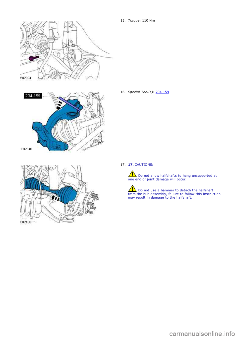
T orque:
110 Nm 15.
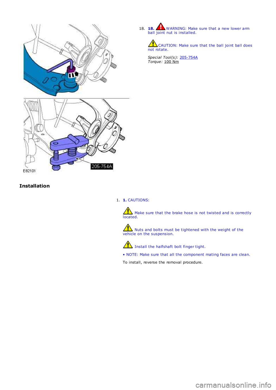
Speci al Tool (s ):
204-159 16.
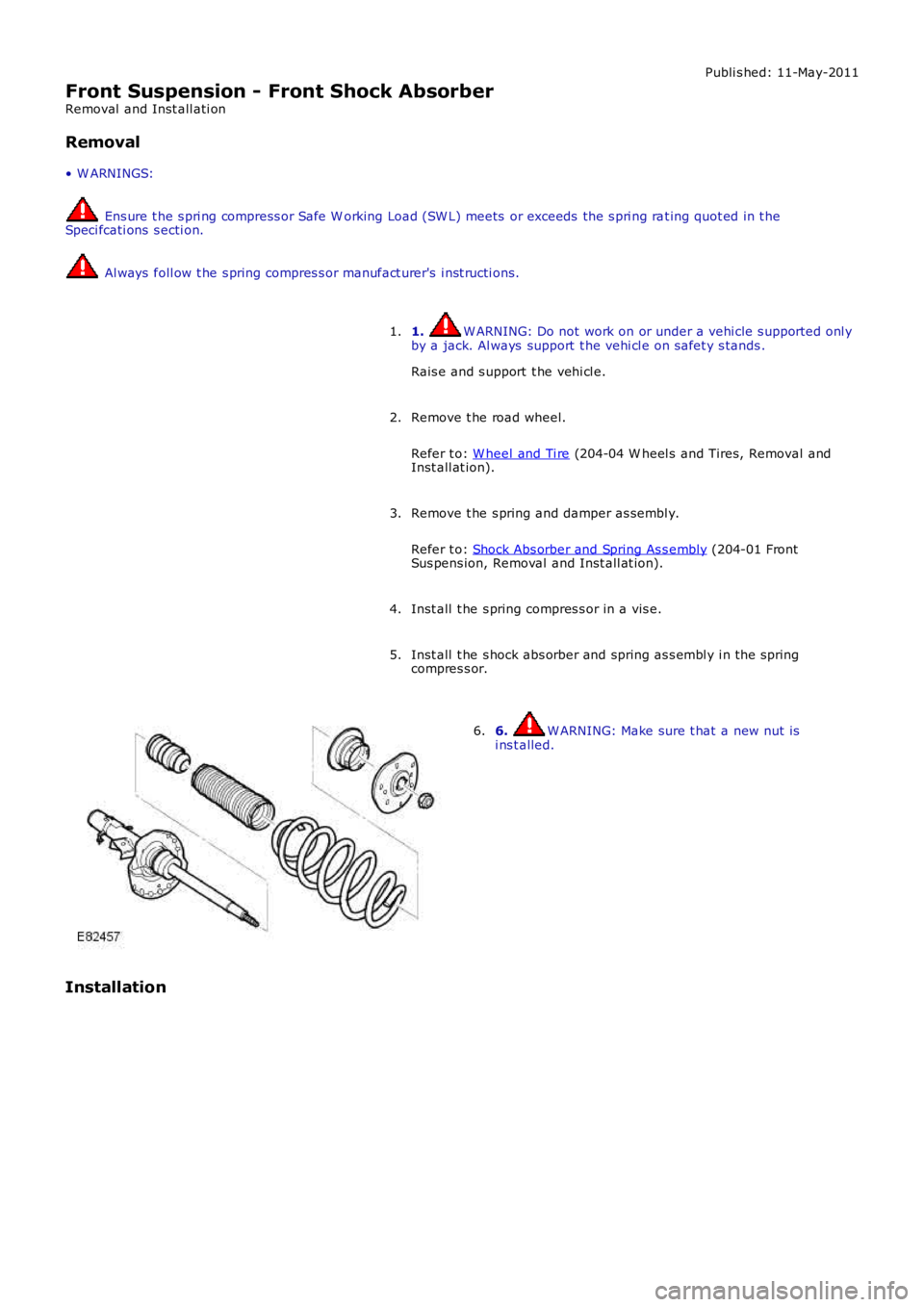
17.
CAUTIONS: Do not al low hal fs haft s to hang uns upported at
one end or joi nt damage will occur. Do not us e a hammer to det ach the hal fs haft
from the hub as s embly, fai lure to foll ow t his i nst ructi on
may res ul t in damage to t he halfs haft.
17.
Page 222 of 3229
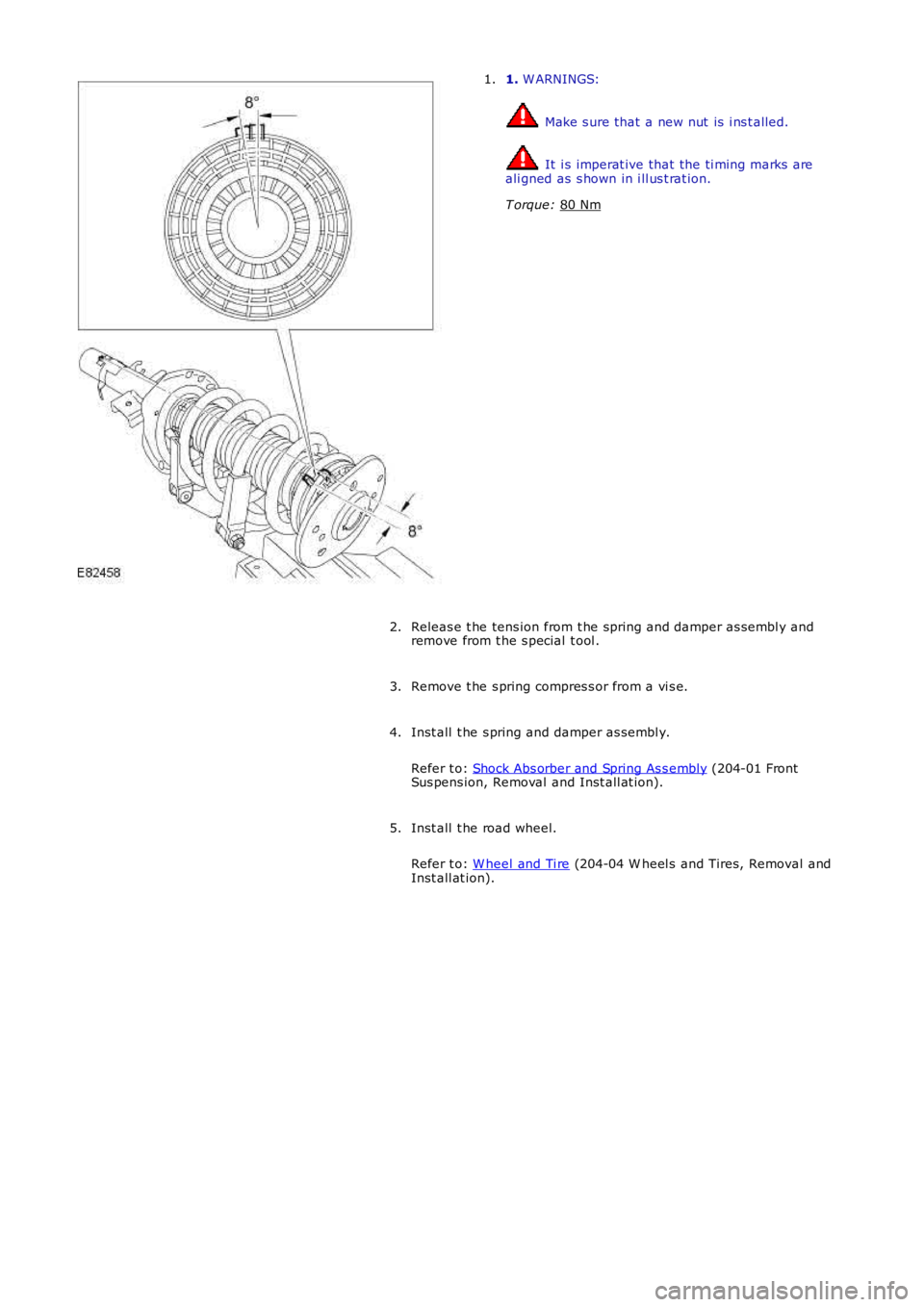
18. W ARNING: Make sure t hat a new lower arm
ball joi nt nut is i ns t alled. CAUTION: Make s ure that t he bal l joi nt bal l does
not rot ate.
Speci al Tool (s ): 205-754A T orque:
100 Nm 18.
Installation 1. CAUTIONS: Make s ure that t he brake hos e is not t wis t ed and is correctl y
l ocated. Nut s and bolt s mus t be t ightened wi th the wei ght of t he
vehicle on the s us pens ion. Ins tall t he halfshaft bol t fi nger t ight.
• NOTE: Make s ure that all t he component mat ing faces are clean.
To i nst all , revers e t he removal procedure.
1.
Page 223 of 3229
Publi s hed: 11-May-2011
Front Suspension - Front Shock Absorber
Removal and Inst all ati on
Removal
• W ARNINGS:
Ens ure t he s pri ng compress or Safe W orking Load (SW L) meets or exceeds the s pri ng rat ing quot ed in t heSpeci fcati ons s ecti on.
Al ways foll ow t he s pring compres s or manufact urer's i nst ructi ons.
1. W ARNING: Do not work on or under a vehi cle s upported onl yby a jack. Al ways support t he vehi cl e on s afet y s tands .
Rais e and s upport t he vehi cl e.
1.
Remove t he road wheel.
Refer t o: W heel and Ti re (204-04 W heel s and Tires, Removal andInst all at ion).
2.
Remove t he s pring and damper as sembl y.
Refer t o: Shock Abs orber and Spring As s embly (204-01 FrontSus pens ion, Removal and Inst all at ion).
3.
Inst all t he s pring compres s or in a vis e.4.
Inst all t he s hock abs orber and spring as s embl y i n the springcompres s or.5.
6. W ARNING: Make sure t hat a new nut isi ns t alled.6.
Installation
Page 224 of 3229
1.
W ARNINGS: Make s ure that a new nut is i ns t alled.
It i s imperat ive that the ti ming marks are
ali gned as s hown in i ll us t rat ion.
T orque: 80 Nm 1.
Releas e t he tens ion from t he spring and damper as sembl y and
remove from t he s pecial t ool .
2.
Remove t he s pring compres s or from a vi s e.
3.
Inst all t he s pring and damper as sembl y.
Refer t o: Shock Abs orber and Spring As s embly (204-01 Front
Sus pens ion, Removal and Inst all at ion).
4.
Inst all t he road wheel.
Refer t o: W heel and Ti re (204-04 W heel s and Tires, Removal and
Inst all at ion).
5.
Page 225 of 3229
Publi s hed: 11-May-2011
Front Suspension - Shock Absorber and Spring Assembly
Removal and Inst all ati on
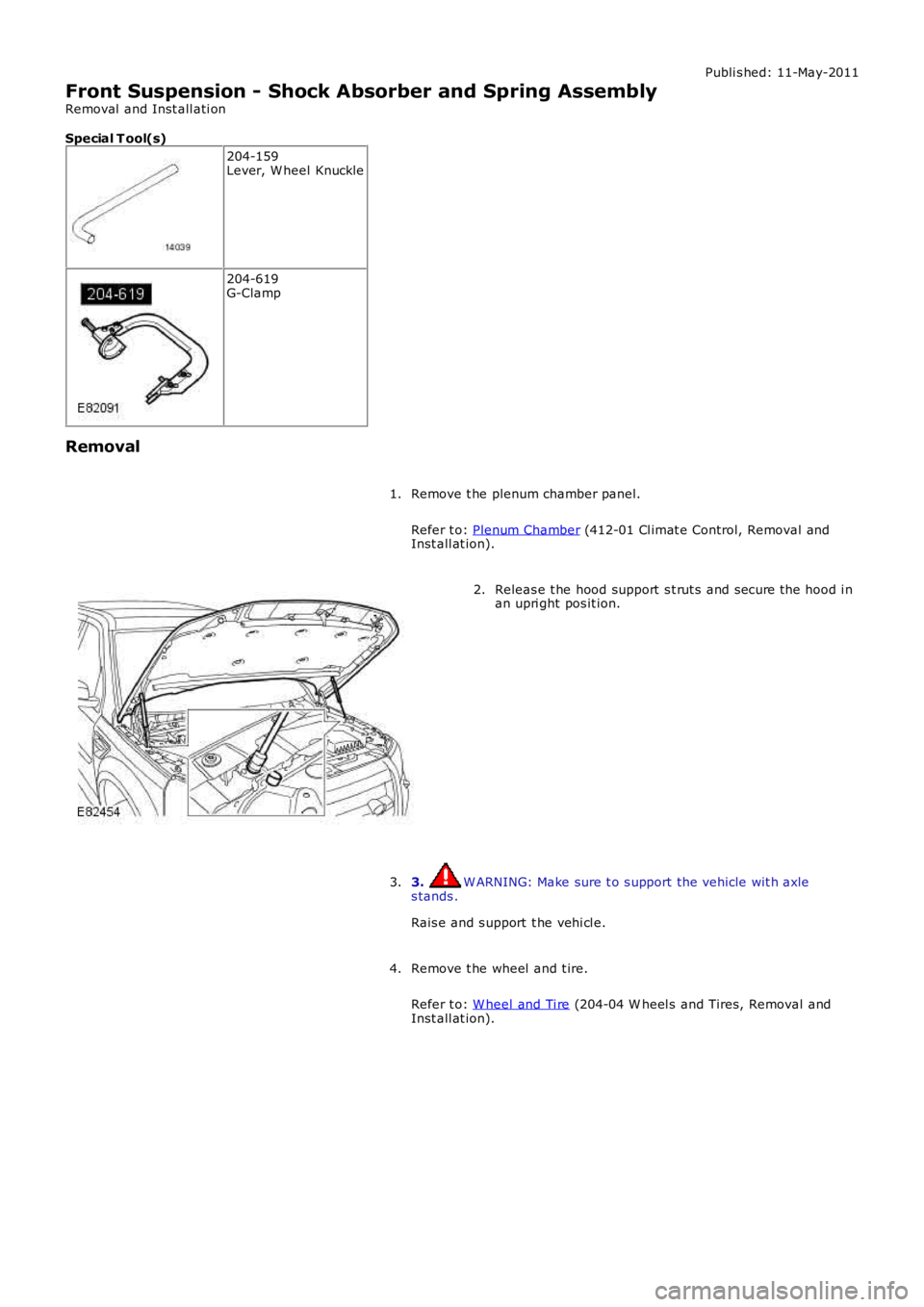
Special T ool(s)
204-159Lever, W heel Knuckle
204-619G-Clamp
Removal
Remove t he plenum chamber panel.
Refer t o: Plenum Chamber (412-01 Cl imat e Control, Removal andInst all at ion).
1.
Releas e t he hood support s t rut s and s ecure the hood i nan upri ght pos it ion.2.
3. W ARNING: Make sure t o s upport the vehicle wit h axles tands .
Rais e and s upport t he vehi cl e.
3.
Remove t he wheel and t ire.
Refer t o: W heel and Ti re (204-04 W heel s and Tires, Removal andInst all at ion).
4.
Page 226 of 3229
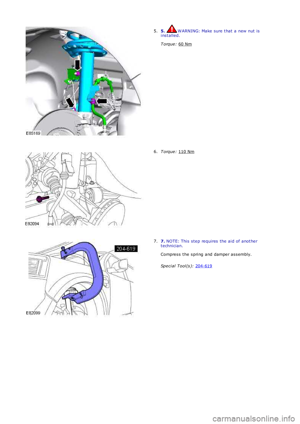
5. W ARNING: Make sure t hat a new nut is
i ns t alled.
T orque: 60 Nm 5.
T orque:
110 Nm 6.
7.
NOTE: Thi s s tep requires the ai d of anot her
t echnician.
Compres s t he s pri ng and damper as s embly.
Speci al Tool (s ): 204-619 7.
Page 227 of 3229
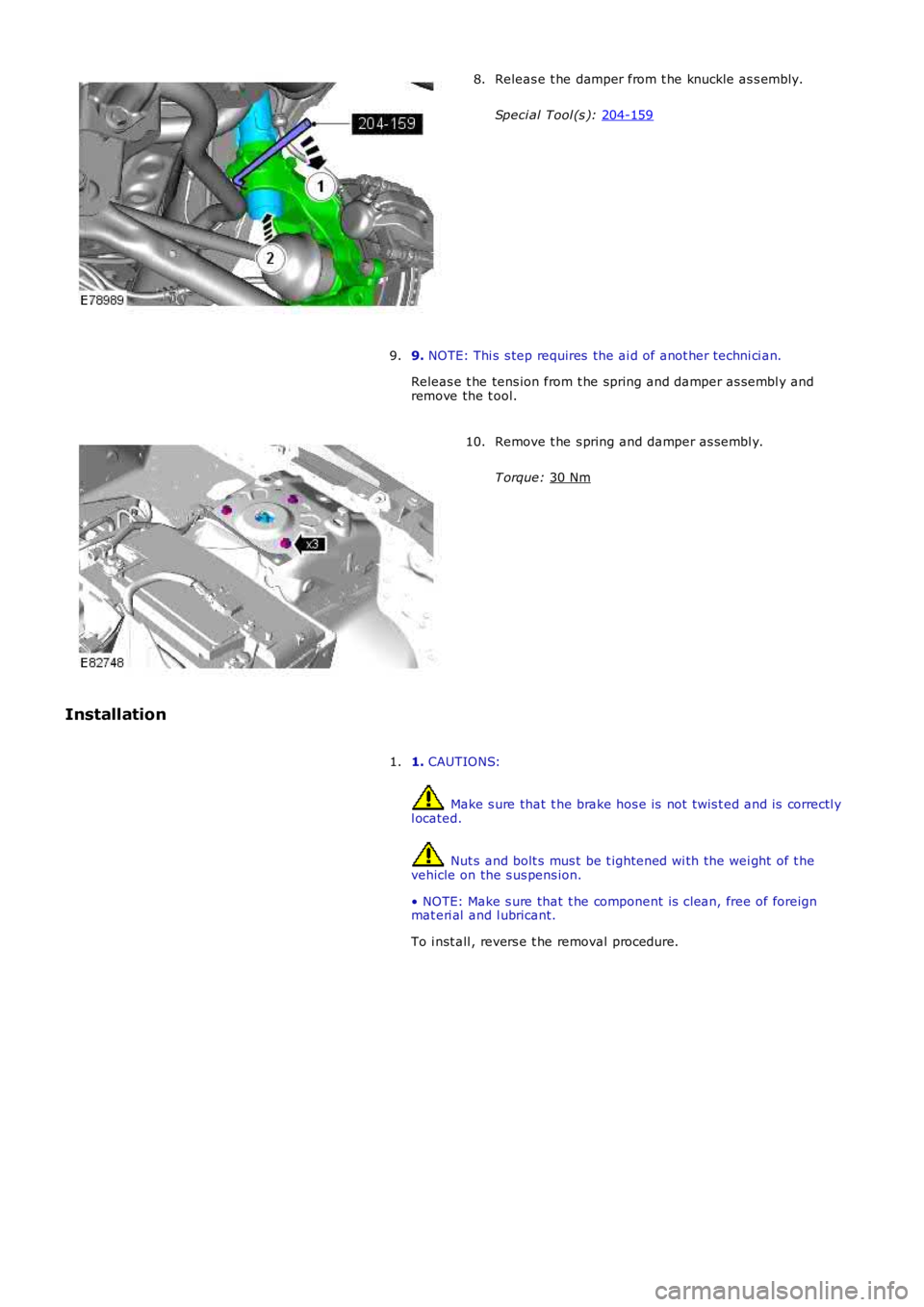
Releas e t he damper from t he knuckle as s embly.
Speci al Tool (s ): 204-159 8.
9. NOTE: Thi s s tep requires the ai d of anot her techni ci an.
Releas e t he tens ion from t he spring and damper as sembl y and
remove the t ool.
9. Remove t he s pring and damper as sembl y.
T orque: 30 Nm 10.
Installation 1. CAUTIONS: Make s ure that t he brake hos e is not t wis t ed and is correctl y
l ocated. Nut s and bolt s mus t be t ightened wi th the wei ght of t he
vehicle on the s us pens ion.
• NOTE: Make s ure that t he component is clean, free of foreign
mat eri al and l ubricant.
To i nst all , revers e t he removal procedure.
1.
Page 228 of 3229
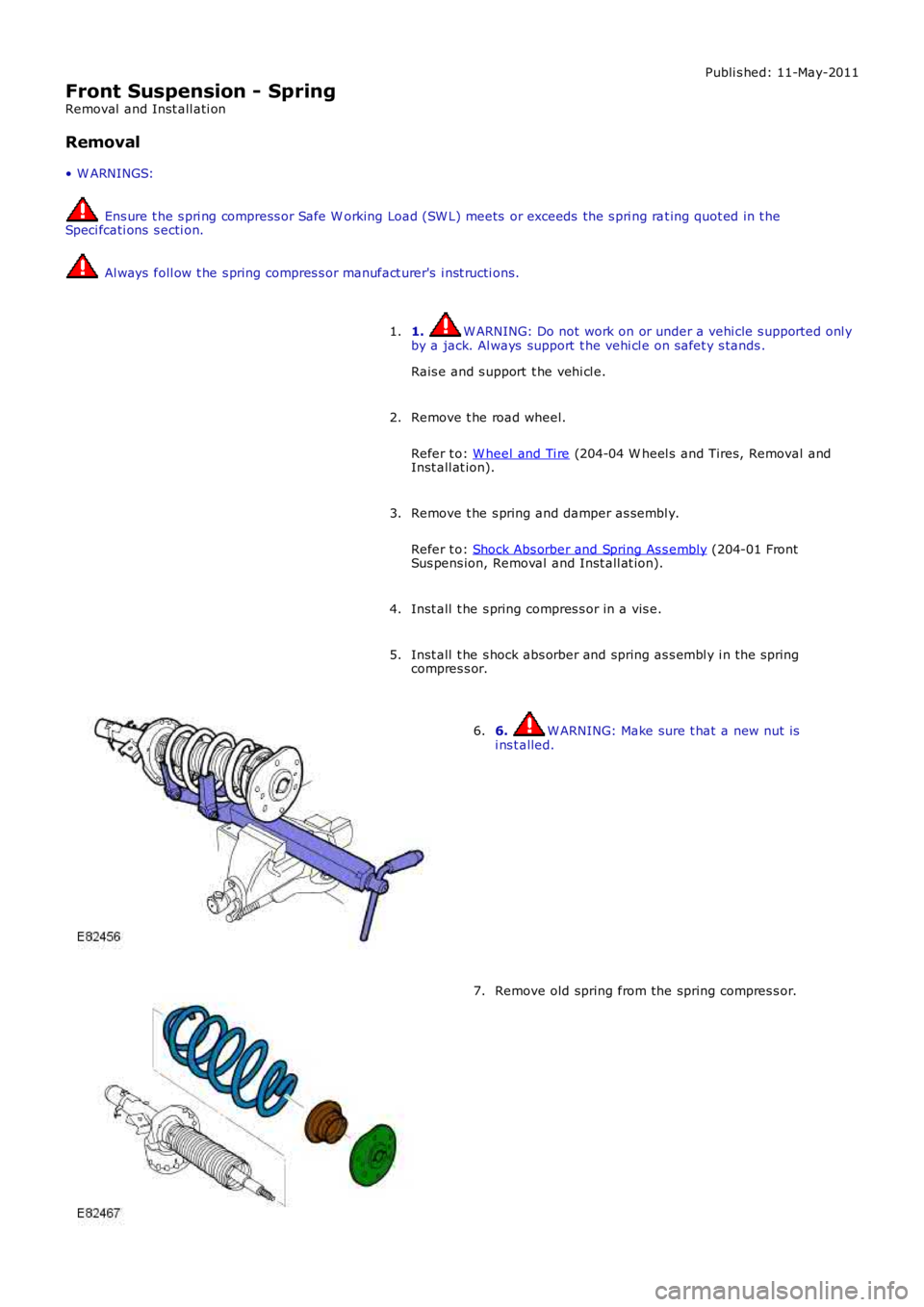
Publi s hed: 11-May-2011
Front Suspension - Spring
Removal and Inst all ati on
Removal
• W ARNINGS:
Ens ure t he s pri ng compress or Safe W orking Load (SW L) meets or exceeds the s pri ng rat ing quot ed in t heSpeci fcati ons s ecti on.
Al ways foll ow t he s pring compres s or manufact urer's i nst ructi ons.
1. W ARNING: Do not work on or under a vehi cle s upported onl yby a jack. Al ways support t he vehi cl e on s afet y s tands .
Rais e and s upport t he vehi cl e.
1.
Remove t he road wheel.
Refer t o: W heel and Ti re (204-04 W heel s and Tires, Removal andInst all at ion).
2.
Remove t he s pring and damper as sembl y.
Refer t o: Shock Abs orber and Spring As s embly (204-01 FrontSus pens ion, Removal and Inst all at ion).
3.
Inst all t he s pring compres s or in a vis e.4.
Inst all t he s hock abs orber and spring as s embl y i n the springcompres s or.5.
6. W ARNING: Make sure t hat a new nut isi ns t alled.6.
Remove old spring from the spring compres s or.7.
Page 229 of 3229
Installation
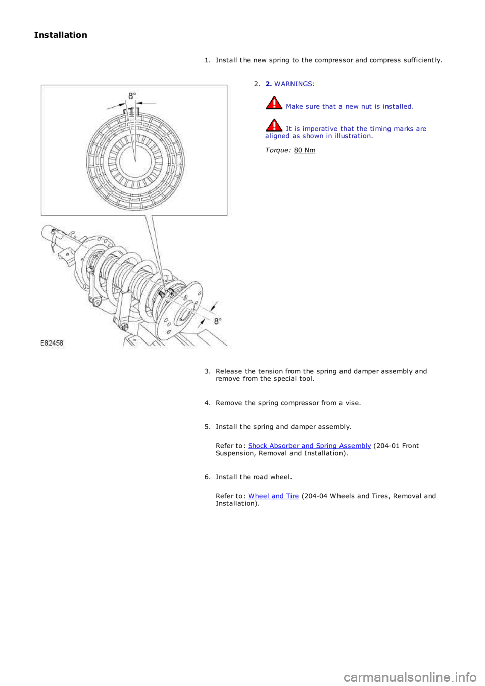
Inst all t he new s pri ng to the compres s or and compress suffi ci ent ly.
1. 2.
W ARNINGS: Make s ure that a new nut is i ns t alled.
It i s imperat ive that the ti ming marks are
ali gned as s hown in i ll us t rat ion.
T orque: 80 Nm 2.
Releas e t he tens ion from t he spring and damper as sembl y and
remove from t he s pecial t ool .
3.
Remove t he s pring compres s or from a vi s e.
4.
Inst all t he s pring and damper as sembl y.
Refer t o: Shock Abs orber and Spring As s embly (204-01 Front
Sus pens ion, Removal and Inst all at ion).
5.
Inst all t he road wheel.
Refer t o: W heel and Ti re (204-04 W heel s and Tires, Removal and
Inst all at ion).
6.
Page 230 of 3229
Publi s hed: 11-May-2011
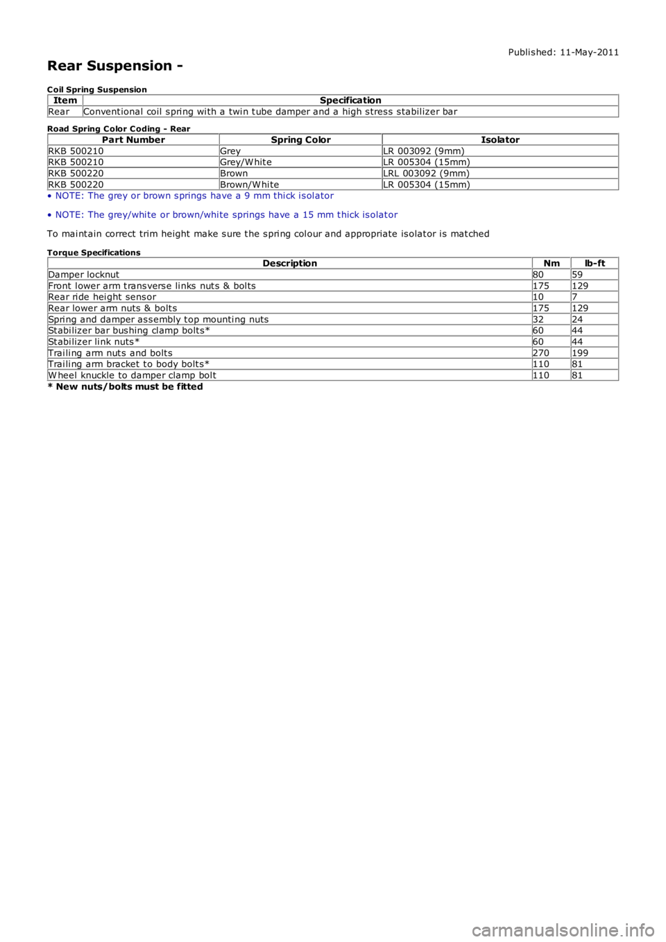
Rear Suspension -
C oil Spring SuspensionItemSpecification
RearConvent ional coil s pri ng wi th a twi n t ube damper and a high s tres s s tabil izer bar
Road Spring C olor C oding - Rear
Part NumberSpring ColorIsolator
RKB 500210GreyLR 003092 (9mm)RKB 500210Grey/W hit eLR 005304 (15mm)
RKB 500220BrownLRL 003092 (9mm)
RKB 500220Brown/W hi teLR 005304 (15mm)• NOTE: The grey or brown s prings have a 9 mm thi ck i s ol ator
• NOTE: The grey/whi te or brown/whi te springs have a 15 mm t hick is olat or
To mai nt ain correct trim height make s ure t he s pri ng col our and appropriate is olat or i s mat ched
Torque SpecificationsDescriptionNmlb-ft
Damper locknut8059
Front l ower arm t rans vers e li nks nut s & bol ts175129Rear ri de hei ght sens or107
Rear lower arm nuts & bolt s175129
Spri ng and damper as s embly t op mounti ng nuts3224St abi lizer bar bus hing cl amp bolt s*6044
St abi lizer li nk nuts *6044
Trai li ng arm nut s and bolt s270199Trai li ng arm bracket t o body bolt s*11081
W heel knuckle to damper clamp bol t11081
* New nuts/bolts must be fitted
Trending: navigation update, change language, maintenance, blower, high beam, navigation, sat nav
