LAND ROVER FRELANDER 2 2006 Repair Manual
FRELANDER 2 2006
LAND ROVER
LAND ROVER
https://www.carmanualsonline.info/img/64/57251/w960_57251-0.png
LAND ROVER FRELANDER 2 2006 Repair Manual
Trending: compression ratio, roof, service schedule, rear entertainment, low beam, timing belt, catalytic converter
Page 2461 of 3229
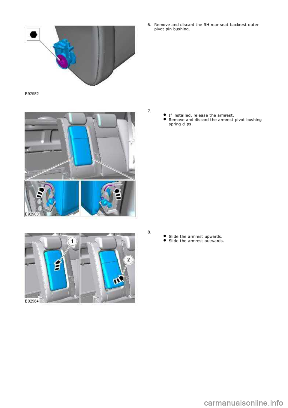
Remove and dis card t he RH rear seat backrest out erpivot pin bus hing.6.
If ins tal led, releas e t he armres t.Remove and dis card t he armres t pivot bus hings pri ng cl ips .
7.
Sli de t he armrest upwards .Sli de t he armrest out wards .
8.
Page 2462 of 3229
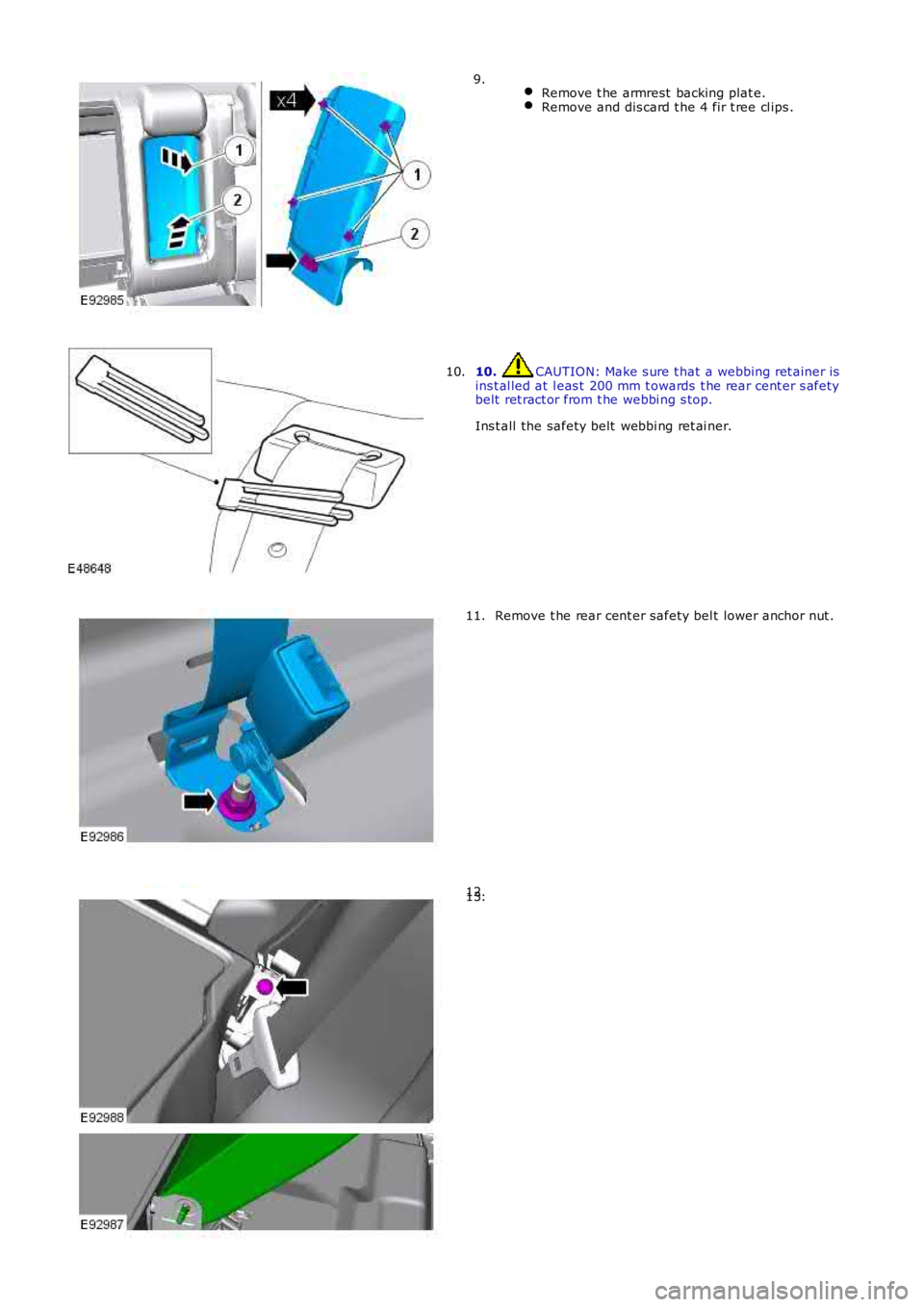
Remove t he armrest backing plat e.Remove and dis card t he 4 fir t ree cl ips .
9.
10. CAUTION: Make s ure t hat a webbing ret ainer isins t al led at l eas t 200 mm t owards t he rear cent er s afetybelt ret ract or from t he webbi ng s top.
Ins t all the safety belt webbi ng ret ai ner.
10.
Remove t he rear cent er safety bel t lower anchor nut .11.
12.13.
Page 2463 of 3229
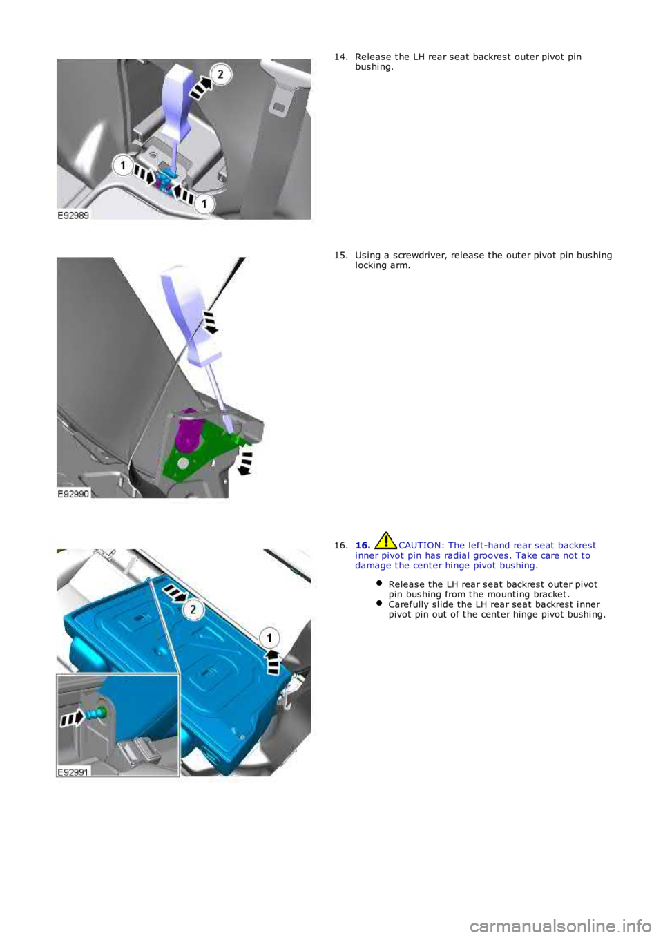
Releas e t he LH rear s eat backres t outer pivot pinbus hi ng.14.
Us ing a s crewdriver, releas e t he out er pivot pin bus hingl ocking arm.15.
16. CAUTION: The left-hand rear s eat backres ti nner pivot pin has radial grooves . Take care not t odamage t he cent er hi nge pivot bus hing.
Releas e t he LH rear s eat backres t outer pivotpin bus hing from t he mounti ng bracket .Carefully sl ide t he LH rear seat backres t i nnerpivot pin out of t he cent er hinge pivot bushi ng.
16.
Page 2464 of 3229
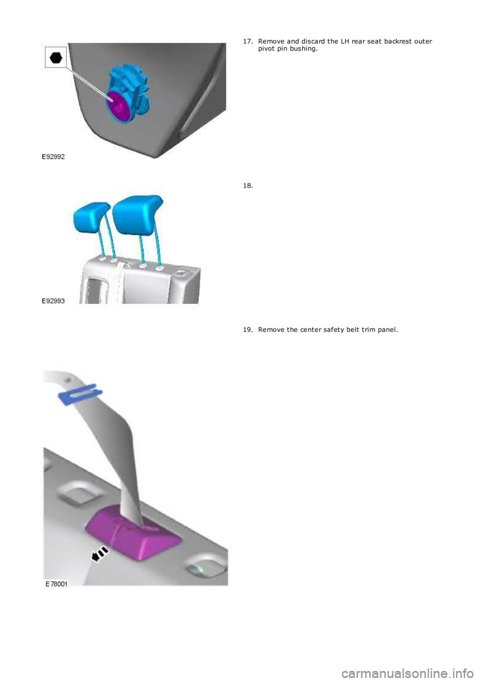
Remove and dis card t he LH rear seat backres t out erpivot pin bus hing.17.
18.
Remove t he cent er safet y belt t rim panel.19.
Page 2465 of 3229
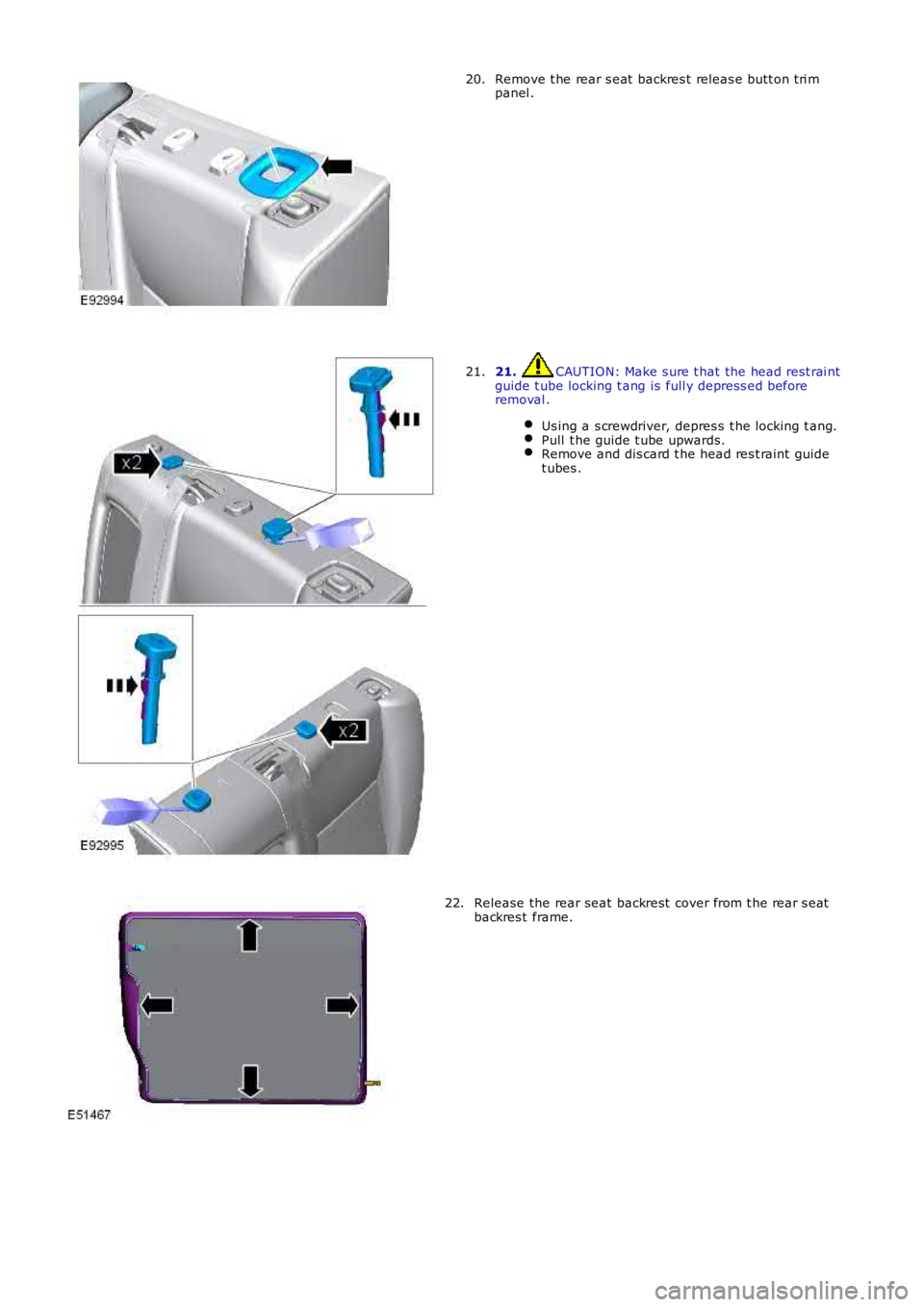
Remove t he rear s eat backres t releas e butt on t ri mpanel .20.
21. CAUTION: Make s ure t hat the head rest rai ntguide t ube locking t ang is full y depress ed beforeremoval .
Us ing a s crewdriver, depres s t he locking t ang.Pull t he guide t ube upwards.Remove and dis card t he head res t raint guidet ubes .
21.
Release the rear seat backrest cover from t he rear s eatbackres t frame.22.
Page 2466 of 3229
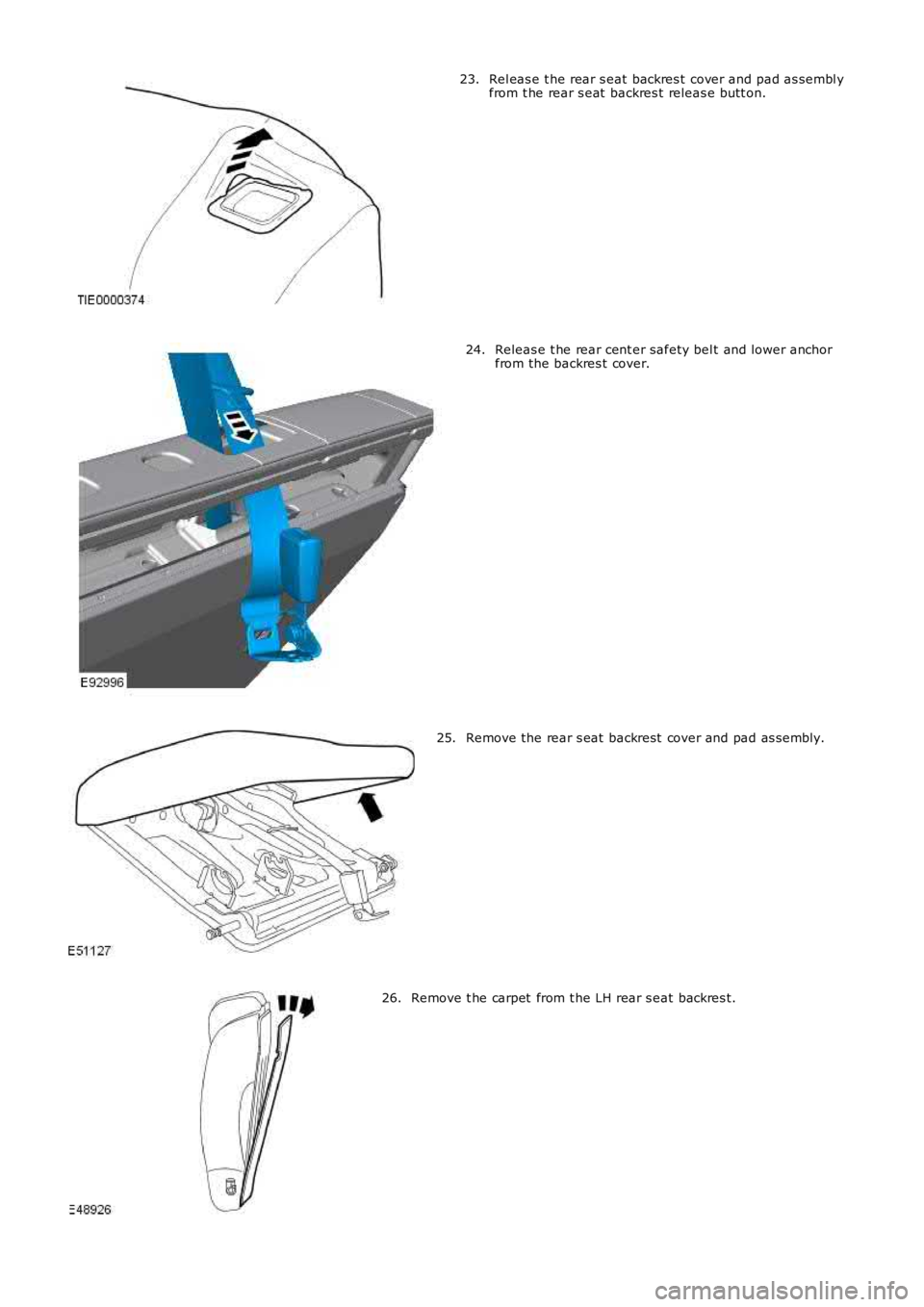
Rel eas e t he rear s eat backres t cover and pad as sembl yfrom t he rear s eat backres t releas e butt on.23.
Releas e t he rear cent er safety bel t and lower anchorfrom the backres t cover.24.
Remove the rear s eat backrest cover and pad as s embly.25.
Remove t he carpet from t he LH rear s eat backres t .26.
Page 2467 of 3229
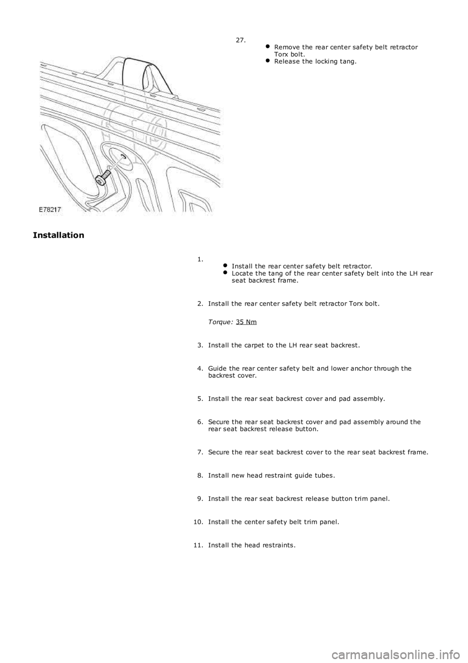
Remove t he rear cent er safety bel t ret ractor
Torx bol t. Releas e t he locki ng t ang.27.
Installation Inst all t he rear cent er safety bel t ret ractor. Locat e t he tang of t he rear center s afety bel t int o t he LH rear
s eat backres t frame. 1.
Inst all t he rear cent er safety bel t ret ractor Torx bolt .
T orque: 35 Nm 2.
Inst all t he carpet to t he LH rear seat backrest .
3.
Guide the rear center s afet y belt and l ower anchor t hrough t he
backrest cover.
4.
Inst all t he rear s eat backres t cover and pad ass embly.
5.
Secure t he rear s eat backres t cover and pad ass embl y around t he
rear s eat backres t rel eas e but ton.
6.
Secure t he rear s eat backres t cover to the rear seat backrest frame.
7.
Inst all new head res t rai nt gui de tubes .
8.
Inst all t he rear s eat backres t releas e butt on t ri m panel.
9.
Inst all t he cent er safet y belt t rim panel.
10.
Inst all t he head res traints .
11.
Page 2468 of 3229
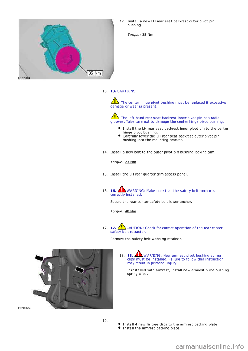
Ins t all a new LH rear s eat backres t out er pivot pi n
bushi ng.
T orque: 35 Nm 12.
13. CAUTIONS: The center hinge pi vot bus hing mus t be repl aced i f exces si ve
damage or wear is pres ent. The l eft -hand rear s eat backres t inner pivot pin has radial
grooves. Take care not t o damage t he cent er hi nge pivot bus hing.
Inst all t he LH rear s eat backres t inner pivot pin t o t he cent er
hinge pi vot bus hing. Carefully lower the LH rear s eat backres t out er pivot pin
bus hi ng int o t he mounti ng bracket . 13.
Inst all a new bol t to the out er pi vot pi n bushi ng locking arm.
T orque: 23 Nm 14.
Inst all t he LH rear quart er trim acces s panel .
15.
16. W ARNING: Make sure t hat t he s afet y bel t anchor is
correct ly i nst all ed.
Secure t he rear cent er s afety bel t lower anchor.
T orque: 40 Nm 16.
17. CAUTION: Check for correct operati on of the rear cent er
s afet y belt ret ract or.
Remove t he s afety bel t webbi ng ret ainer.
17. 18. W ARNING: New armrest pi vot bus hing s pri ng
clips must be ins tall ed. Fail ure to foll ow t hi s i ns t ructi on
may resul t in personal injury.
If i nst all ed wit h armres t , ins tall new armres t pi vot bus hi ng
s pring cl ips .
18.
Inst all 4 new fi r tree cl ips t o t he armres t backing pl ate. Inst all t he armrest backing plat e.19.
Page 2469 of 3229
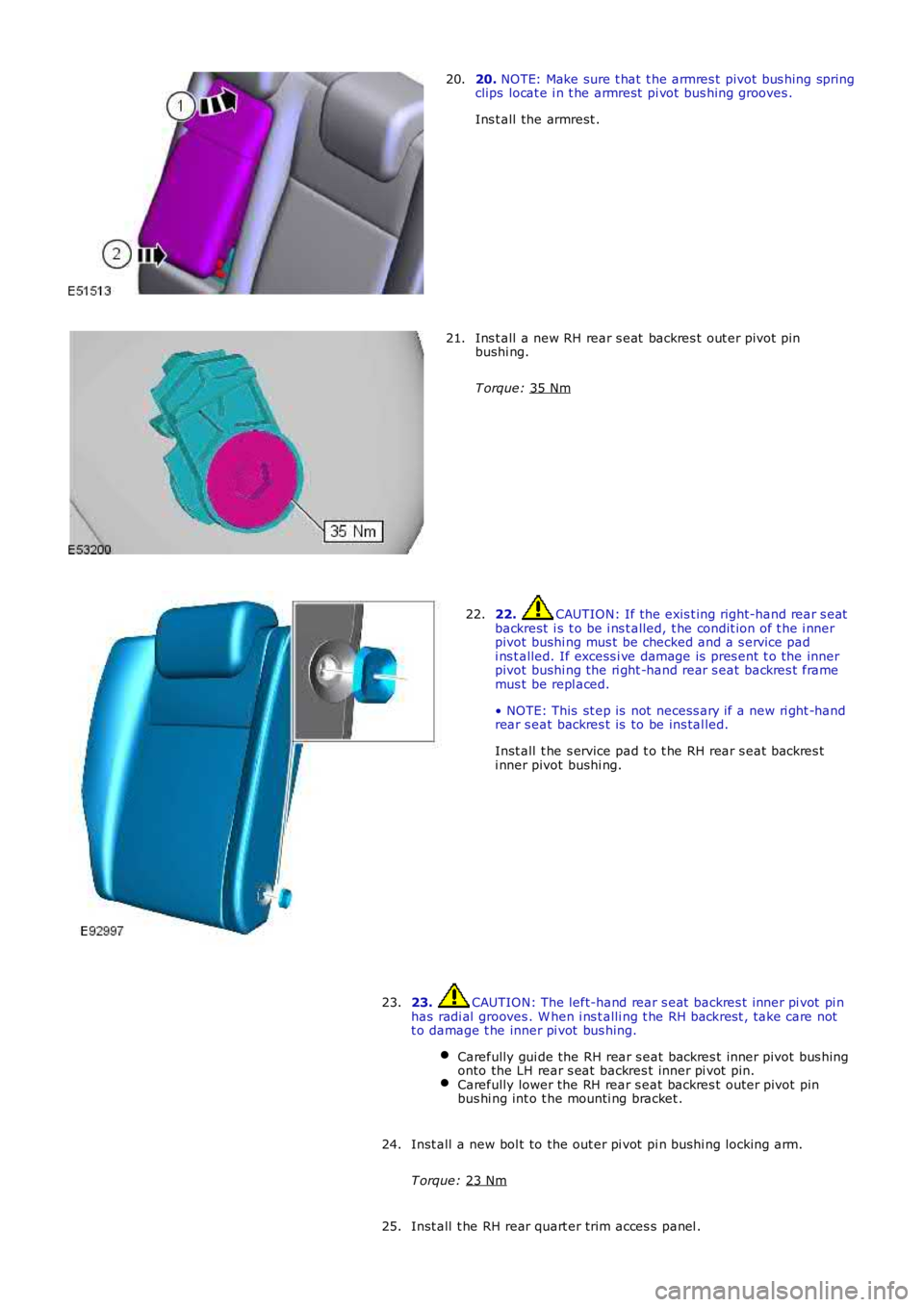
20.
NOTE: Make sure t hat t he armres t pivot bus hing spring
clips locat e i n t he armrest pi vot bus hing grooves .
Ins t all the armrest .
20. Ins t all a new RH rear s eat backres t out er pivot pin
bushi ng.
T orque: 35 Nm 21.
22. CAUTION: If the exis t ing right-hand rear s eat
backrest i s t o be i ns t alled, t he condit ion of t he i nner
pivot bushi ng mus t be checked and a s ervice pad
i ns t alled. If excess i ve damage is pres ent t o the inner
pivot bushi ng the ri ght -hand rear s eat backres t frame
mus t be repl aced.
• NOTE: This st ep is not necess ary if a new ri ght -hand
rear s eat backres t is to be ins tal led.
Inst all t he s ervice pad t o t he RH rear s eat backres t
i nner pivot bushi ng.
22.
23. CAUTION: The left-hand rear s eat backres t inner pi vot pi n
has radi al grooves . W hen i ns t alli ng t he RH backrest , take care not
t o damage t he inner pi vot bus hing.
Carefully gui de the RH rear s eat backres t inner pivot bus hing
onto the LH rear s eat backres t inner pi vot pi n. Carefully lower the RH rear s eat backres t outer pivot pin
bus hi ng int o t he mounti ng bracket . 23.
Inst all a new bol t to the out er pi vot pi n bushi ng locking arm.
T orque: 23 Nm 24.
Inst all t he RH rear quart er trim acces s panel .
25.
Page 2470 of 3229
Publi s hed: 11-May-2011
Safety Belt System - Front Safety Belt Buckle
Removal and Inst all ati on
Removal
• NOTE: Removal s t eps in t his procedure may cont ain i nst all ati on det ail s.
Di sconnect t he bat t ery ground cable.
Refer t o: Specificati ons (414-00 Bat tery and Charging Sys tem -General Informat ion, Specificati ons).
1.
Make t he SRS s ys t em s afe.
Refer t o: Supplement al Res t raint Sys tem (SRS) Depowering andRepowering (501-20, General Procedures ).
2.
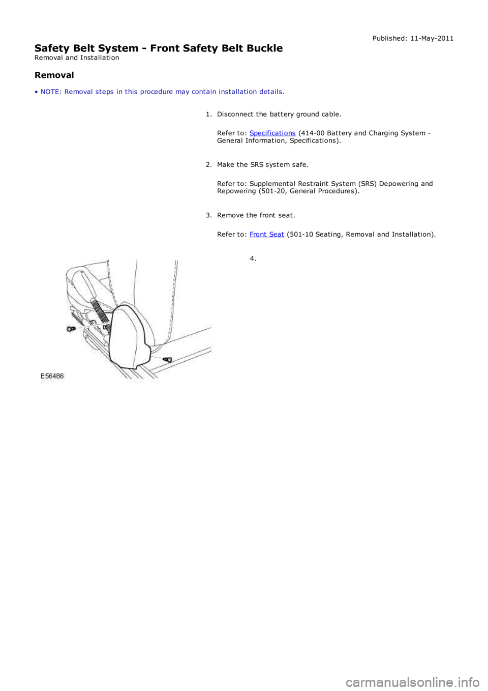
Remove t he front seat .
Refer t o: Front Seat (501-10 Seati ng, Removal and Ins tal lati on).
3.
4.
Trending: brake pads replacement, height adjustment, change time, emergency towing, ESP, oil temperature, change language
