LAND ROVER FRELANDER 2 2006 Service Manual
Manufacturer: LAND ROVER, Model Year: 2006, Model line: FRELANDER 2, Model: LAND ROVER FRELANDER 2 2006Pages: 3229, PDF Size: 78.5 MB
Page 41 of 3229
Some operat ions may produce high noi se levels whi ch could, i n ti me, damage hearing. In thes e cases , s uit abl e earprot ect ion mus t be worn.
Solder
Solders are mi xtures of met als such t hat t he mel ti ng point of the mixture i s bel ow that of t he const it uent metals (normal lylead and t in). Sol der appli cat ion does not normal ly gi ve ri se to toxic l ead fumes , provided a gas /ai r fl ame i s used.Oxy-acet ylene flames s hould not be us ed, as they are much hot t er and will cause lead fumes to be produced.
Some fumes may be produced by t he appl icati on of any fl ame t o s urfaces coat ed wi th grease, and i nhalat ion of t heses houl d be avoided.
Removal of exces s s older s houl d be undertaken wi th care, t o make sure t hat fine l ead dus t i s not produced, which can givet oxi c effect s if i nhal ed. Res pirat ory protecti on may be necess ary.
Solder spi ll age and fil ings s houl d be coll ect ed and removed promptl y to prevent general air contami nat ion by lead.
High st andards of pers onal hygi ene are necess ary in order t o avoid inges t ion of l ead or i nhal ati on of sol der dus t fromclothi ng.
Solvents
For example acet one, whi te s pirit , t ol uene, xylene, trichloroet hane.
Us ed in cl eani ng and dewaxi ng materials , paint s, pl as t ics , res ins and t hinners .
Some may be highly flammabl e or fl ammable.
Skin contact wil l degreas e t he s kin and may res ult i n irri tat ion and dermati ti s fol lowing repeat ed or prolonged cont act.Some can be abs orbed t hrough the s kin in t oxic or harmful quant it ies .
Splas hes in t he eye may cause severe irri tat ion and coul d l ead to los s of vi s ion.
Bri ef expos ure of high concent rat ions of vapors or mis t s wil l caus e eye and t hroat irri tat ion, drows ines s, di zzines s ,headaches and, i n t he wors t circums t ances , unconscious nes s .
Repeat ed or prolonged expos ure to excess i ve but l ower concent rat ions of vapors or mis t s , for which t here might not beadequat e warni ng indicati ons , can caus e more s eri ous toxic or harmful effect s .
As pi rat ion i nto the l ungs , for example through vomi ti ng, i s the most serious cons equence of s wall owi ng.
Avoi d s plas hes to the s kin, eyes and cl othi ng. W ear prot ecti ve gl oves , goggl es and clothi ng if neces s ary.
Make s ure t here i s good vent il ati on when in us e, avoi d breat hing fumes, vapors and spray mis t s and keep contai nerst ightl y s eal ed. Do not us e i n confined s paces .
W hen s praying materials contai ning s olvents , for example pai nt s , adhes ives , and metal coat ings , use ext racti onvent il ati on or pers onal res piratory prot ect ion i n t he abs ence of adequate general venti lati on.
Do not apply heat or fl ame except under s peci fi c and detail ed manufacturers i ns t ructi ons .
Suspended Loads
CAUTION: Never improvi se lift ing t ackle.
There i s always a danger when loads are lifted or s us pended. Never work under an unsupported, s us pended or rais ed l oad,for example a s us pended engi ne.
Always make s ure that l ift ing equi pment s uch as jacks , hoi st s , axl e s tands and s li ngs are adequat e and s uit abl e for thejob, i n good condit ion and regul arl y maint ained.
Viton
In common wi th many ot her manufact urers vehi cl es, s ome components i nst all ed to Land Rover vehi cl es have seals , 'O 'ri ngs or gas kets whi ch cont ain a material known as 'Vit on'.
Vit on is a fluoroelas tomer, that i s a s ynt heti c rubber type whi ch contai ns Fluori ne. Al though Vit on is the mos t wel l knownfl uoroelas tomer, there are ot hers , including Fl uorel and Tecmofl on.
W hen us ed under des ign condit ions fl uoroelas tomers are perfectl y s afe. If, however, they are expos ed t o t emperatures inexces s of 400°C, t he material wil l not burn, but wi ll decompos e, and one of the products formed is hydrofluori c acid.
This acid is extremely corros ive and may be abs orbed di rectl y, t hrough cont act , int o t he general body s ys tem. WHERECASES OF SKIN CONT ACT OCCUR, SEEK IMMEDIAT E MEDICAL HELP.
O-ri ngs , s eal s or gaskets which have been expos ed to very high t emperat ures wi ll appear charred or as a black s ti ckys ubs t ance.
DO NOT, under any ci rcums tances touch t hem or the at t ached component s.
Enqui ri es should be made t o determine whet her Vi ton or any ot her fluoroel as t omer has been us ed i n the affect ed O-ring,s eal or gas ket . If t hey are of nat ural rubber or ni trile there is no hazard. If in doubt , be caut ious as t he material may beVit on or any fl uoroelas tomer.
If Vi ton or any ot her fluoroel as t omers have been us ed, t he affect ed area should be decontami nated before t he
Page 42 of 3229
commencement of work.
Dis pos abl e heavy dut y plas ti c gloves s houl d be worn at all ti mes , and the affected area was hed down usi ng wire wool anda l imewat er (calcium hydroxi de) s olut ion t o neutrali se the acid before di spos ing of t he decompos ed Vit on res i due and fi nalcleaning of t he area. Aft er us e, t he plas ti c gloves should be dis carded carefull y and s afely.
Welding
W el di ng process es i ncl ude Res i st ance W elding (Spot W eldi ng), Arc W elding and Gas W eldi ng.
Resistance Welding
This proces s may cause parti cles of molt en met al to be emit ted at a high velocit y, and t he eyes and s ki n mus t beprot ect ed.
Arc Weld ing
This proces s emit s a hi gh level of ul tra-vi ol et radiat ion whi ch may caus e arc-eye and s ki n burns t o t he operator and t oother pers ons nearby. Gas -shi el ded welding proces s es are parti cul arly hazardous i n thi s res pect . Pers onal prot ecti on mus tbe worn, and s creens us ed to shi eld ot her people.
CONTACT LENS W EARERS ARE ADVISED TO REVERT TO ORDINARY SPECTACLES W HEN ARC W ELDING as t he arc spectrumis bel ieved to emit microwaves which dry out t he fluid bet ween t he lens and t he eye. This may res ult i n bli ndnes s whent he lens is removed from the eye.
Metal s patt er wil l al so occur, and appropri ate eye and skin prot ect ion i s neces s ary.
The heat of t he weldi ng arc wi ll produce fumes and gas es from the metals bei ng welded, the rods and from any appli edcoat ings or cont aminat ion on t he s urfaces being worked on. Thes e gas es and fumes may be toxic and inhalati on of thes es houl d be avoided. The us e of extract ion vent ilat ion t o remove the fumes from the working area may be neces s arypart icularl y in cas es where the general vent il ati on is poor, or where cons iderabl e weldi ng work i s anti ci pated. In ext remecas es or confined s paces where adequat e vent il ati on cannot be provided, air-fed res pirators may be neces s ary.
CAUTION: Some of t he components ins tal led t o t he vehi cl e e.g. t he int eri or cros s beam and underbonnet crossmember are manufact ured from magnesi um al loy. On no account s houl d any welding operat ions be at t empt ed on t hesecomponents .
Gas Welding (and Cutting)
Oxy-acet ylene t orches may be us ed for wel di ng and cutt ing, and s pecial care mus t be t aken to prevent l eakage of t hes egases , wit h consequent ri sk of fire and explos ion.
The process wil l produce met al spat ter and eye and s kin prot ecti on is necess ary.
The fl ame i s bri ght , and eye prot ect ion s hould be us ed, but t he ult ra-violet emi s si on is much les s than t hat from arcweldi ng, and l ighter filt ers may be us ed.
The process it sel f produces few t oxi c fumes , but s uch fumes and gases may be produced from coati ngs on the work,part icularl y duri ng cut ti ng away of damaged body parts , and inhalat ion of t he fumes s hould be avoided.
In brazing, toxic fumes may be produced from t he metal s in the brazi ng rod, and a s evere hazard may ari se if brazing rodscont aining cadmi um are used. In t hi s event parti cular care must be taken t o avoi d i nhalat ion of fumes and expert advi cemay be requi red.
SPECIAL PRECAUT IO NS MUST BE T AKEN BEFORE ANY WELDING OR CUT T ING T AKES PLACE ON VESSELS WHICHHAVE CO NT AINED COMBUST IBLE MAT ERIALS, FO R EXAMPLE BO ILING O R ST EAMING O UT OF FUEL T ANKS.
Warning Symbols on Vehicles
Decal s s howi ng warni ng s ymbol s wil l be found on various vehi cl e component s.
Thes e decals mus t not be removed. The warni ngs are for the at tent ion of owners /operat ors and persons carrying outs ervice or repair operat ions on t he vehicle.
Page 43 of 3229
Publi s hed: 11-May-2011
General Information - Solvents, Sealants and Adhesives
Des cript ion and Operat ion
Solvents
W ARNING: Always handl e all s olvents , s eal ers and adhesi ves wit h extreme care. Some contain chemi cal s or give offfumes which can be dangerous to healt h. Always fol low the manufact urers ins truct ions. If i n doubt about any subs tance,part icularl y a s olvent, DO NOT us e i t.
CAUTION: If in doubt about t he s uit abi li ty of any proprietary s olvent or s ealer for a parti cul ar appl icat ion, cont act themanufacturer of t he product for informat ion.
The Healt h and Safet y Precaut ions s ubsecti on refers t o s ome commonl y used chemi cal s and materials , hazards as sociat edwit h t heir us e, and s afet y meas ures t o be t aken. Some of t hese chemi cal s may be i ncluded as an ingredient i n a s ealer oradhes ive.
Sealers
Cert ain procedures i n t hi s manual invol ve t he use of s ealant s during ins tall ati on of components . W here a s ealant isrequired, the appli cat ion, together wi th the Land Rover part number i s given in the General Speci fi cat ion at t he s tart ofeach secti on and an i ns t ructi on t hat a sealant mus t be us ed appears in the relevant repair procedure.
It is es s ent ial t hat t he s ealant(s ) specified for a part icular procedure are us ed, DO NO T use any other s eal ant .
Always remove traces of old s eal ant us ing a plas ti c s craper or s uit abl e s olvent, never us e emery cloth or metal s crapers .
Adhesives
W henever a procedure involves the us e of an adhes ive, the adhesi ve s pecified must be us ed and t he manufacturer'sins t ructi ons regarding appli cat ion t oget her wit h any healt h and s afety precaut ions mus t be fol lowed.
Page 44 of 3229
Publi s hed: 11-May-2011
General Information - Road/Roller Testing
Des cript ion and Operat ion
Road or roll ing road t es t ing may be carri ed out for various reasons and a procedure det ail ing pre-t es t checks , throughengi ne s tarti ng and s topping, pre-driving checks , on-t es t checks to final checks on complet ion of t he tes t are given.
Unles s complete vehi cl e performance is bei ng checked, t he ful l road t est procedure need not be carried out . Ins tead, t hos eit ems part icularly relevant t o t he s yst em(s) bei ng checked can be ext racted.
Pre-Test Checks
W ARNING: If t he brake s yst em hydraul ic fluid level i s l ow, pedal travel i s exces si ve or a hydraulic leak is found, donot att empt to road t est t he vehicle unt il t he reas on for t he low fl ui d l evel, excess ive pedal travel or hydraulic leak isfound and rect ified.
It is s ugges t ed that pre-t es t and funct ional t es ts of t hose sys tems/circuit s whi ch affect t he safe and l egal operati ons oft he vehi cl e, s uch as brakes , light s and s teeri ng, should al ways be carri ed out before the road or roll ing road tes t .
Engi ne oil l evelEngi ne cool ant levelTires, for correct pres sure, compat ible types and tread patt erns , and wear wi thi n limi ts .There i s s ufficient fuel in the t ank to compl ete the t est .Check al l around the engine, t rans mis s ion and under the vehicle for oil , coolant , hydraul ic and fuel l eaks . Make anote of any apparent leaks and wipe off t he surrounding areas t o make it easi er to identi fy t he extent of the leakon complet ion of t he tes t.
Starting the Engine
• NOTE: On i nit ial dri ve away from cold and wit hi n t he fi rs t 1.5 km (1 mile), do not depress accelerat or pedal beyond halft ravel unt il t he vehi cl e has att ained a minimum s peed of 25 km/h (15 mil es /h). Never operat e at high engi ne speed or wi tht he accelerat or pedal at ful l travel whil st the engine i s cold.
With the ignition off, check:
The parking brake is appli ed.Automatic transmission: The s el ect or lever is i n 'P' - PARK.Manual transmission: The gear l ever i s in NEUTRAL.All i ns t rument gauges read zero.
With the ignition on, check:
Igni ti on cont roll ed warni ng li ght s come on.Engi ne t emperature gauge regis t ers a readi ng compat ibl e wi th t he engine t emperat ure.Fuel gauge regi st ers a reading appropriate to the fuel l evel i n t he tank.The operati on of the parki ng brake warning l ight and fl ui d l evel warni ng indicator light.
On Road Test Check:
CAUTION: At commencement of road tes ti ng, check the brake operati on while s ti ll travel li ng at low speed beforecont inuing wit h t he tes t. If t he brakes pul l to one si de, or appear to be ot herwi se fault y, do not cont inue wit h t he roadt es t unti l the fault has been found and rect ified.
The parking brake releas es completel y.Gear changing i s s mooth, and t here are no abnormal noi s es or vi brati ons from t he t rans mis s ion.The engi ne power out put is s ati s factory, accel erati on is smoot h and accel erator pedal operat ion is not s ti ff orheavy, and engi ne s peed ret urns t o idl e correctl y.There i s no exces s ive or abnormall y colored s moke from t he engi ne under normal driving, heavy l oad or overruncondi ti ons .Steering operat ion i s s moot h, accurat e, not exces s ively heavy or wit h exces s ive free pl ay or vibrat ion. Does not pul lt o one s ide and s elf centres smoot hly after corneri ng.All i ns t rument s regis t er the correct readi ngs and operate correctl y.Swit ches and controls operat e s moothl y and posi ti vel y, warning or i ndi cat or light s operate correctl y and thedirect ion i ndi cat or cont rol s elf cancels when the s t eering i s ret urned t o t he s traight ahead pos it ion.Heati ng and vent il at ion sys tems work correct ly and effect ively.Brakes operate efficientl y.
Brake Testing
Avoi d brake t es ti ng on busy roads where i t can caus e i nconveni ence or danger t o ot her road users.
CAUTION: Brake t es ti ng which i ncludes heavy brake appl icati ons should not be carri ed out wit h new brake pads /dis csunti l the component s have bedded-i n. New brake fri ct ion component s wi ll not reach ful l efficiency unt il t he beddi ng-inprocess is complet e. Not e t hat when new parking brake shoes or rear brake di scs have been ins t al led, it i s es sent ial thatt he 'beddi ng-in' procedure i s carri ed out.For addit ional informat ion, refer t o: Parking Brake Shoes Bedding-In (206-05 Parking Brake and Actuati on, GeneralProcedures).
Test t he brakes at s everal speeds wit hin the normal operat ing range usi ng both light and heavy pedal pres s ure. Note anyt endency to snat ch, pull or drag, and any undue del ay in appli cat ion or release.
Page 45 of 3229
All ow t he vehi cl e t o coas t and note any tendency t o pull t o one s ide, or evi dence t hat the brakes are binding.
Aft er s topping t he vehi cl e (not immedi at ely after a period of heavy braking), careful ly check the brake temperat ure. A di s cwhich feel s appreciably hot ter t han the ot hers , could indicate that t he pads on that dis c are binding.
Aft er compl eti on of the t es t, check for:
Oil , cool ant , hydraul ic, air and fuel l eaks .Abnormal temperature of any movi ng components or as s embli es , e.g. wheel hubs , t rans mis s ion et c., which mightindicat e over t ight nes s or lack of lubricati on.
Rolling Road Testing
Four-Wheel Rolling Road
CAUTION: W hen ut il is ing a four-wheel roll ing road for t est ing, ensure all relevant healt h and s afet y requirements areadhered t o.
Provided t hat front and rear roll ers are rot ati ng at identi cal s peeds and t hat normal works hop s afety st andards are appli ed,t here is no s peed res tricti on during tes ti ng except any that may apply to the t ires.
Ensure t hat t he parking brake is releas ed pri or t o engaging rol ler dri ving mechani s m.
Two-Wheel Rolling Road
CAUTION: On no account s hould an at t empt be made t o carry out any form of tes t ing on a two-wheel rolli ng road.
Page 46 of 3229
Publi s hed: 11-May-2011
General Information - Special Tool Glossary
Des cript ion and Operat ion
Service Tools
Speci al s ervi ce tools have been devel oped to faci li tat e removal, di smant li ng and as sembl y of mechanical components in acos t effecti ve and ti me effi ci ent manner. The us e of s uch s pecial t ool s als o helps prevent t he potenti al for damage tocomponents .
Some operat ions described in thi s manual cannot be carried out properly wi thout t he aid of t he rel evant s ervice t ools .
All orders and enqui ri es from t he Unit ed Kingdom and European count ries except Germany, Aus tria, Swit zerland and Spainand count ri es not i n t he fol lowing lis t s hould be s ent direct t o:
SPX UK Ltd.,
Genoa Hous e,
Everdon Park,
Davent ry,
Nort hant s ,
NN11 5Y J
Engl and
T el: 0044 (0) 1327 303467/303455
Fax: 0044 (0) 1327 706632
e-mail: s pxs al esuk@s ervi ces oluti ons.s px.com
Overs eas orders for the foll owing count ries s houl d be placed wi th the l ocal dis t ribut or.
Germany, Aust ria and Swi tzerl and
SPX Europe GMBH,
Pors ches t ras se 4,
63512 Hai nburg,
Germany
T el: 0049 61829590
Fax: 0049 6182959299
Spai n
SPX Iberica SA,
C/Francis co Arit io,
158 nave 72 (Nudo O es t e),
19004 Guadalajara,
Spai n
T el: 0034 949208381
Fax: 0034 949208327
Nort h America
SPX Corporation
665, Ei senhower Dri ve,
Owat onna,
MN 55060,
USA
T el: 0018 772979110
Fax: 0018 005787375
Aust ral ia
SPX Australia,
Page 47 of 3229

28, Clayton Road,
Nott ing Hill ,
Vict oria 3168,
Aust ral ia
T el: 0061 00395446222
Fax: 0061 00395445222
e-mail: s ales @s px.com.au
Japan and Eas t As ia
Jatek Ltd.,
5 - 53, Mi nawacho 2-chome,
Kohoku-ku,
Y okohama,
Kanagawa 223-0051,
Japan
T el: 0081 455627700
Fax: 0081 455627800
Page 48 of 3229
Publ is hed: 28-Apr-2011
General Information - Diagnostic Trouble Code (DTC) IndexDTC: Audio
Amplifier Module (AAM)
Des cript ion and Operat ion
• NOTE: If a cont rol module or component i s s uspect and the vehicl e remai ns under manufacturer warrant y, refer t o t heW arranty Pol icy and Procedures manual (s ect ion B1.2), or determine i f any pri or approval program is i n operat ion, beforet he replacement of a component.
• NOTE: Generic scan t ool s may not read the codes li st ed, or may read only 5-digi t codes . Match t he 5 digi ts from t he s cant ool t o t he fi rs t 5 di gi ts of the 7-digit code li s ted t o i dent ify the fault (the last 2 digi ts gi ve ext ra informati on read by themanufacturer-approved di agnos ti c s ys t em).
• NOTE: W hen performing volt age or res is t ance t est s , always use a digi tal mult imeter (DMM) accurat e t o t hree deci malplaces, and wi th an up-t o-date cal ibrat ion cert ificate. W hen tes ti ng res is t ance al ways take t he res is t ance of t he DMMleads i nt o account .
• NOTE: Check and recti fy bas ic faul ts before beginni ng diagnos t ic rout ines i nvol vi ng pinpoint t es t s.
• NOTE: Ins pect connect ors for s igns of water ingres s , and pins for damage and/or corros ion.
• NOTE: If DTCs are recorded and, aft er performi ng the pi npoi nt tes ts , a fault is not present , an int ermi tt ent concern maybe t he caus e. Always check for loose connect ions and corroded terminals .
Des cript ion And Operat ion
For a detail ed descripti on of the audio ampli fier s ys tem, refer to the relevant Des cri pti on and Operati on s ect ion i n t heworks hop manual .For addit ional informat ion, refer t o: Audi o Sys tem (415-01 Informati on and Entertainment Sys tem, Des cript ion andOperat ion).
Audio Amplifier Module (AAM)
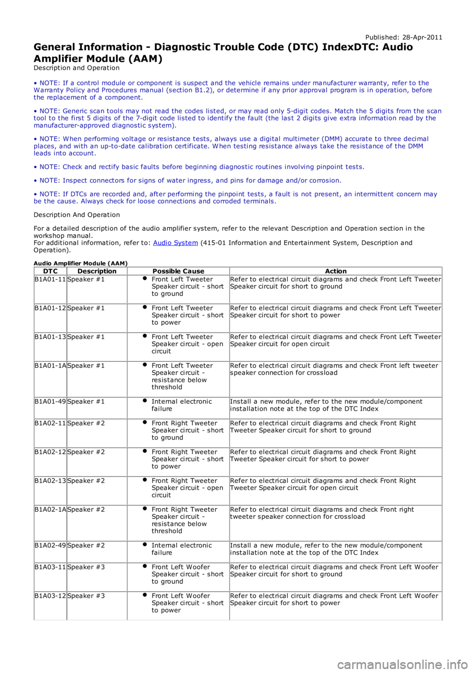
DT CDescriptionPossible CauseAction
B1A01-11Speaker #1Front Left TweeterSpeaker ci rcuit - s hortto ground
Refer to el ect ri cal circui t diagrams and check Front Left Tweet erSpeaker circui t for s hort t o ground
B1A01-12Speaker #1Front Left TweeterSpeaker ci rcuit - s hortto power
Refer to el ect ri cal circui t diagrams and check Front Left Tweet erSpeaker circui t for s hort t o power
B1A01-13Speaker #1Front Left TweeterSpeaker ci rcuit - opencircuit
Refer to el ect ri cal circui t diagrams and check Front Left Tweet erSpeaker circui t for open circui t
B1A01-1ASpeaker #1Front Left TweeterSpeaker ci rcuit -res is t ance belowthreshold
Refer to el ect ri cal circui t diagrams and check Front left tweeters peaker connect ion for cros s load
B1A01-49Speaker #1Int ernal electroni cfai lureIns tall a new module, refer to the new modul e/componenti nst all ati on not e at t he t op of the DTC Index
B1A02-11Speaker #2Front Right TweeterSpeaker ci rcuit - s hortto ground
Refer to el ect ri cal circui t diagrams and check Front RightTweet er Speaker circui t for s hort t o ground
B1A02-12Speaker #2Front Right TweeterSpeaker ci rcuit - s hortto power
Refer to el ect ri cal circui t diagrams and check Front RightTweet er Speaker circui t for s hort t o power
B1A02-13Speaker #2Front Right TweeterSpeaker ci rcuit - opencircuit
Refer to el ect ri cal circui t diagrams and check Front RightTweet er Speaker circui t for open circui t
B1A02-1ASpeaker #2Front Right TweeterSpeaker ci rcuit -res is t ance belowthreshold
Refer to el ect ri cal circui t diagrams and check Front ri ghtt weeter s peaker connecti on for cros s load
B1A02-49Speaker #2Int ernal electroni cfai lureIns tall a new module, refer to the new modul e/componenti nst all ati on not e at t he t op of the DTC Index
B1A03-11Speaker #3Front Left W ooferSpeaker ci rcuit - s hortto ground
Refer to el ect ri cal circui t diagrams and check Front Left W ooferSpeaker circui t for s hort t o ground
B1A03-12Speaker #3Front Left W ooferSpeaker ci rcuit - s hortto power
Refer to el ect ri cal circui t diagrams and check Front Left W ooferSpeaker circui t for s hort t o power
Page 49 of 3229
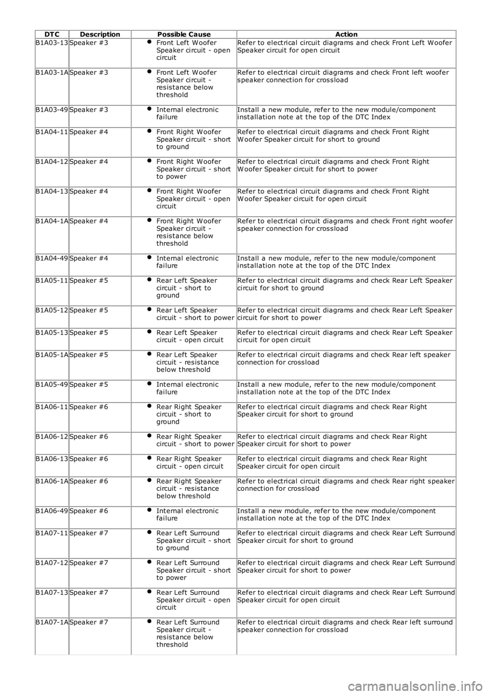
DT CDescriptionPossible CauseAction
B1A03-13Speaker #3Front Left W ooferSpeaker ci rcuit - opencircuit
Refer to el ect ri cal circui t diagrams and check Front Left W ooferSpeaker circui t for open circui t
B1A03-1ASpeaker #3Front Left W ooferSpeaker ci rcuit -res is t ance belowthreshold
Refer to el ect ri cal circui t diagrams and check Front left woofers peaker connect ion for cros s load
B1A03-49Speaker #3Int ernal electroni cfai lureIns tall a new module, refer to the new modul e/componenti nst all ati on not e at t he t op of the DTC Index
B1A04-11Speaker #4Front Right W ooferSpeaker ci rcuit - s hortto ground
Refer to el ect ri cal circui t diagrams and check Front RightW oofer Speaker ci rcuit for short to ground
B1A04-12Speaker #4Front Right W ooferSpeaker ci rcuit - s hortto power
Refer to el ect ri cal circui t diagrams and check Front RightW oofer Speaker ci rcuit for short to power
B1A04-13Speaker #4Front Right W ooferSpeaker ci rcuit - opencircuit
Refer to el ect ri cal circui t diagrams and check Front RightW oofer Speaker ci rcuit for open ci rcuit
B1A04-1ASpeaker #4Front Right W ooferSpeaker ci rcuit -res is t ance belowthreshold
Refer to el ect ri cal circui t diagrams and check Front ri ght woofers peaker connect ion for cros s load
B1A04-49Speaker #4Int ernal electroni cfai lureIns tall a new module, refer to the new modul e/componenti nst all ati on not e at t he t op of the DTC Index
B1A05-11Speaker #5Rear Left Speakercircuit - short toground
Refer to el ect ri cal circui t diagrams and check Rear Left Speakerci rcuit for s hort t o ground
B1A05-12Speaker #5Rear Left Speakercircuit - short to powerRefer to el ect ri cal circui t diagrams and check Rear Left Speakerci rcuit for s hort t o power
B1A05-13Speaker #5Rear Left Speakercircuit - open circui tRefer to el ect ri cal circui t diagrams and check Rear Left Speakerci rcuit for open circui t
B1A05-1ASpeaker #5Rear Left Speakercircuit - res is tancebelow t hres hold
Refer to el ect ri cal circui t diagrams and check Rear l eft s peakerconnect ion for cross l oad
B1A05-49Speaker #5Int ernal electroni cfai lureIns tall a new module, refer to the new modul e/componenti nst all ati on not e at t he t op of the DTC Index
B1A06-11Speaker #6Rear Ri ght Speakercircuit - short toground
Refer to el ect ri cal circui t diagrams and check Rear Ri ghtSpeaker circui t for s hort t o ground
B1A06-12Speaker #6Rear Ri ght Speakercircuit - short to powerRefer to el ect ri cal circui t diagrams and check Rear Ri ghtSpeaker circui t for s hort t o power
B1A06-13Speaker #6Rear Ri ght Speakercircuit - open circui tRefer to el ect ri cal circui t diagrams and check Rear Ri ghtSpeaker circui t for open circui t
B1A06-1ASpeaker #6Rear Ri ght Speakercircuit - res is tancebelow t hres hold
Refer to el ect ri cal circui t diagrams and check Rear right s peakerconnect ion for cross l oad
B1A06-49Speaker #6Int ernal electroni cfai lureIns tall a new module, refer to the new modul e/componenti nst all ati on not e at t he t op of the DTC Index
B1A07-11Speaker #7Rear Left SurroundSpeaker ci rcuit - s hortto ground
Refer to el ect ri cal circui t diagrams and check Rear Left SurroundSpeaker circui t for s hort t o ground
B1A07-12Speaker #7Rear Left SurroundSpeaker ci rcuit - s hortto power
Refer to el ect ri cal circui t diagrams and check Rear Left SurroundSpeaker circui t for s hort t o power
B1A07-13Speaker #7Rear Left SurroundSpeaker ci rcuit - opencircuit
Refer to el ect ri cal circui t diagrams and check Rear Left SurroundSpeaker circui t for open circui t
B1A07-1ASpeaker #7Rear Left SurroundSpeaker ci rcuit -res is t ance belowthreshold
Refer to el ect ri cal circui t diagrams and check Rear l eft s urrounds peaker connect ion for cros s load
Page 50 of 3229
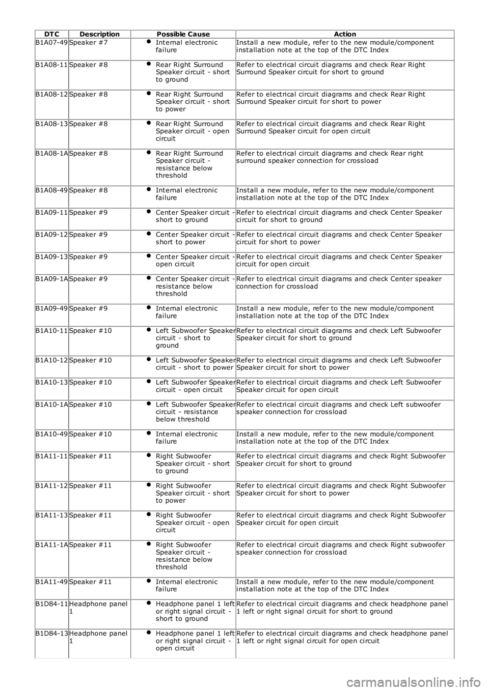
DT CDescriptionPossible CauseAction
B1A07-49Speaker #7Int ernal electroni cfai lureIns tall a new module, refer to the new modul e/componenti nst all ati on not e at t he t op of the DTC Index
B1A08-11Speaker #8Rear Ri ght SurroundSpeaker ci rcuit - s hortto ground
Refer to el ect ri cal circui t diagrams and check Rear Ri ghtSurround Speaker circuit for s hort to ground
B1A08-12Speaker #8Rear Ri ght SurroundSpeaker ci rcuit - s hortto power
Refer to el ect ri cal circui t diagrams and check Rear Ri ghtSurround Speaker circuit for s hort to power
B1A08-13Speaker #8Rear Ri ght SurroundSpeaker ci rcuit - opencircuit
Refer to el ect ri cal circui t diagrams and check Rear Ri ghtSurround Speaker circuit for open ci rcuit
B1A08-1ASpeaker #8Rear Ri ght SurroundSpeaker ci rcuit -res is t ance belowthreshold
Refer to el ect ri cal circui t diagrams and check Rear rights urround s peaker connect ion for cros sl oad
B1A08-49Speaker #8Int ernal electroni cfai lureIns tall a new module, refer to the new modul e/componenti nst all ati on not e at t he t op of the DTC Index
B1A09-11Speaker #9Cent er Speaker ci rcuit -s hort to groundRefer to el ect ri cal circui t diagrams and check Cent er Speakerci rcuit for s hort t o ground
B1A09-12Speaker #9Cent er Speaker ci rcuit -s hort to powerRefer to el ect ri cal circui t diagrams and check Cent er Speakerci rcuit for s hort t o power
B1A09-13Speaker #9Cent er Speaker ci rcuit -open ci rcuitRefer to el ect ri cal circui t diagrams and check Cent er Speakerci rcuit for open circui t
B1A09-1ASpeaker #9Cent er Speaker ci rcuit -res is t ance belowthreshold
Refer to el ect ri cal circui t diagrams and check Cent er speakerconnect ion for cross l oad
B1A09-49Speaker #9Int ernal electroni cfai lureIns tall a new module, refer to the new modul e/componenti nst all ati on not e at t he t op of the DTC Index
B1A10-11Speaker #10Left Subwoofer Speakercircuit - short toground
Refer to el ect ri cal circui t diagrams and check Left SubwooferSpeaker circui t for s hort t o ground
B1A10-12Speaker #10Left Subwoofer Speakercircuit - short to powerRefer to el ect ri cal circui t diagrams and check Left SubwooferSpeaker circui t for s hort t o power
B1A10-13Speaker #10Left Subwoofer Speakercircuit - open circui tRefer to el ect ri cal circui t diagrams and check Left SubwooferSpeaker circui t for open circui t
B1A10-1ASpeaker #10Left Subwoofer Speakercircuit - res is tancebelow t hres hold
Refer to el ect ri cal circui t diagrams and check Left s ubwoofers peaker connect ion for cros s load
B1A10-49Speaker #10Int ernal electroni cfai lureIns tall a new module, refer to the new modul e/componenti nst all ati on not e at t he t op of the DTC Index
B1A11-11Speaker #11Right SubwooferSpeaker ci rcuit - s hortto ground
Refer to el ect ri cal circui t diagrams and check Right SubwooferSpeaker circui t for s hort t o ground
B1A11-12Speaker #11Right SubwooferSpeaker ci rcuit - s hortto power
Refer to el ect ri cal circui t diagrams and check Right SubwooferSpeaker circui t for s hort t o power
B1A11-13Speaker #11Right SubwooferSpeaker ci rcuit - opencircuit
Refer to el ect ri cal circui t diagrams and check Right SubwooferSpeaker circui t for open circui t
B1A11-1ASpeaker #11Right SubwooferSpeaker ci rcuit -res is t ance belowthreshold
Refer to el ect ri cal circui t diagrams and check Right s ubwoofers peaker connect ion for cros s load
B1A11-49Speaker #11Int ernal electroni cfai lureIns tall a new module, refer to the new modul e/componenti nst all ati on not e at t he t op of the DTC Index
B1D84-11Headphone panel1Headphone panel 1 leftor ri ght s i gnal circuit -s hort to ground
Refer to el ect ri cal circui t diagrams and check headphone panel1 left or right s ignal ci rcuit for short to ground
B1D84-13Headphone panel1Headphone panel 1 leftor ri ght s i gnal circuit -open ci rcuit
Refer to el ect ri cal circui t diagrams and check headphone panel1 left or right s ignal ci rcuit for open ci rcuit