LAND ROVER FRELANDER 2 2006 Repair Manual
FRELANDER 2 2006
LAND ROVER
LAND ROVER
https://www.carmanualsonline.info/img/64/57251/w960_57251-0.png
LAND ROVER FRELANDER 2 2006 Repair Manual
Trending: air condition, oil dipstick, emergency towing, battery location, engine coolant, check transmission fluid, trailer
Page 661 of 3229
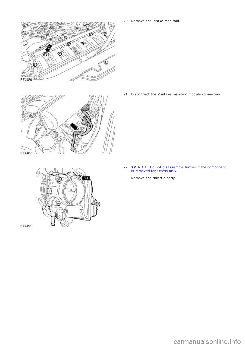
Remove t he int ake mani fol d.20.
Di sconnect t he 2 i nt ake manifold module connect ors .21.
22. NOTE: Do not dis ass emble further if t he componenti s removed for acces s onl y.
Remove t he thrott le body.
22.
Page 662 of 3229
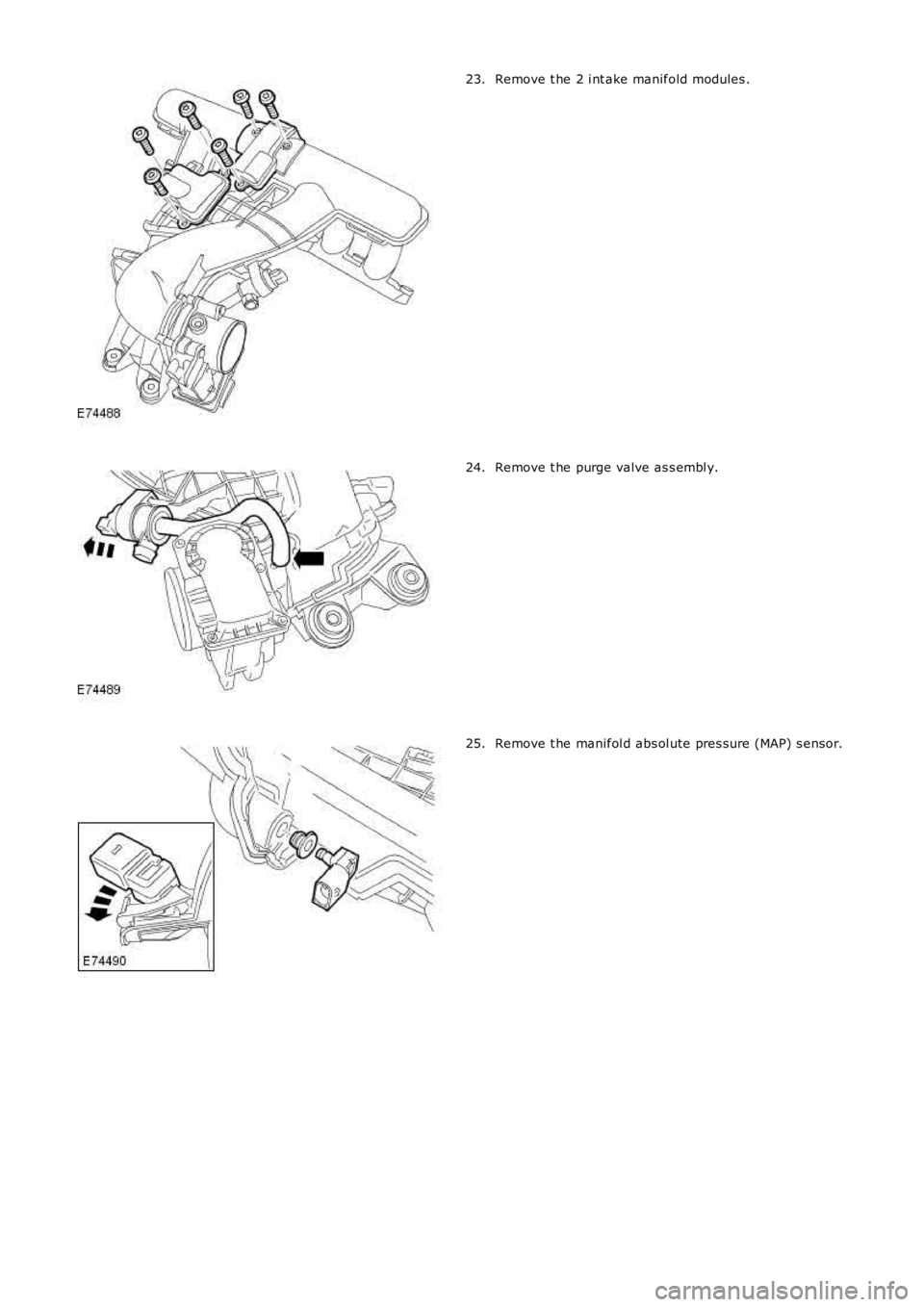
Remove t he 2 i nt ake manifold modules .23.
Remove t he purge valve as s embl y.24.
Remove t he manifol d abs ol ute pres sure (MAP) s ens or.25.
Page 663 of 3229
Remove and dis card t he i nt ake manifold gas ket s .
26.
Installation Clean t he component mat ing faces .
1.
Inst all t he gas kets .
2.
Inst all t he int ake mani fol d modules .
3.
Inst all t he MAP s ensor.
4.
Inst all t he purge valve as s embl y.
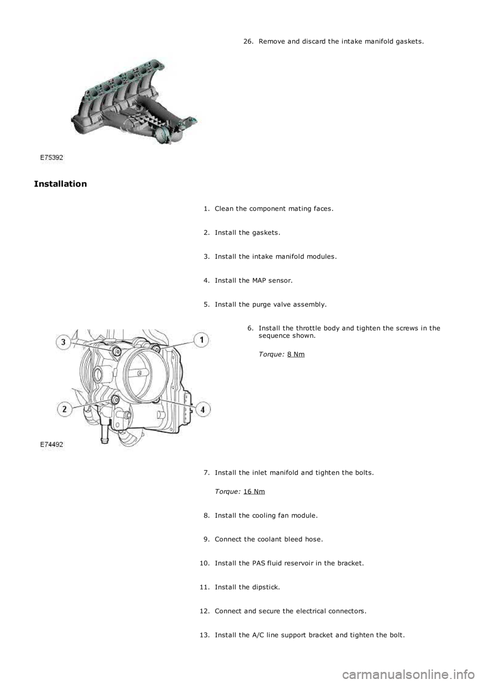
5. Inst all t he thrott le body and t ighten the s crews i n t he
s equence s hown.
T orque: 8 Nm 6.
Inst all t he inlet mani fold and ti ght en t he bolt s.
T orque: 16 Nm 7.
Inst all t he cool ing fan module.
8.
Connect t he cool ant bl eed hos e.
9.
Inst all t he PAS fl uid reservoi r in the bracket.
10.
Inst all t he dips ti ck.
11.
Connect and s ecure t he electrical connect ors .
12.
Inst all t he A/C li ne support bracket and ti ghten t he bolt .
13.
Page 664 of 3229
T orque:
10 Nm Connect t he purge l ine.
14.
Inst all t he lower int ake manifol d bolt s .
T orque: 10 Nm 15.
Inst all t he air cleaner out let pipe.
16.
Inst all t he engi ne undershi eld.
Refer t o: Engi ne Unders hi eld (501-02 Front End Body Panel s ,
Removal and Ins tall ati on).
17.
Inst all t he front unders hiel d.
18.
Inst all t he front towing eye cover.
19.
Inst all t he air cleaner as s embly.
Refer t o: Air Cleaner (303-12B Intake Ai r Dis tribut ion and Fil tering -
TD4 2.2L Dies el, Removal and Inst all ati on).
20.
Inst all t he engi ne cover.
Refer t o: Engi ne Cover - I6 3.2L Pet rol (501-05 Int eri or Trim and
Ornament ati on, Removal and Ins tal lat ion).
21.
Connect t he batt ery ground cable.
Refer t o: Specificati ons (414-00 Bat tery and Charging Sys tem -
General Informat ion, Specificati ons).
22.
Check and top-up the coolant.
23.
Page 665 of 3229
Publi s hed: 11-May-2011
Engine - I6 3.2L Petrol - Variable Valve Timing (VVT) Unit
Removal and Inst all ati on
Removal
CAUTION: Extreme cleanli nes s mus t be exercis ed when handli ng thes e component s.
• NOTE: This procedure is t he s ame as t he t imi ng chai n and gears procedure.
Remove t he cover and dis connect the bat tery ground cabl e.
Refer t o: Specificati ons (414-00 Bat tery and Charging Sys tem -General Informat ion, Specificati ons).
1.
Remove t he variable val ve ti ming (VVT) unit .
Refer t o: Timi ng Chai n (303-01A Engi ne - I6 3.2L Pet rol, Removaland Inst all at ion).
2.
Installation
Inst all t he VVT unit .
Refer t o: Timi ng Chai n (303-01A Engi ne - I6 3.2L Pet rol, Removaland Inst all at ion).
1.
Connect t he batt ery ground cable and ins tall t he cover.
Refer t o: Specificati ons (414-00 Bat tery and Charging Sys tem -General Informat ion, Specificati ons).
2.
Page 666 of 3229
Publ ished: 11-May-2011
Engine - I6 3.2L Petrol - Valve Cover
Removal and Installation
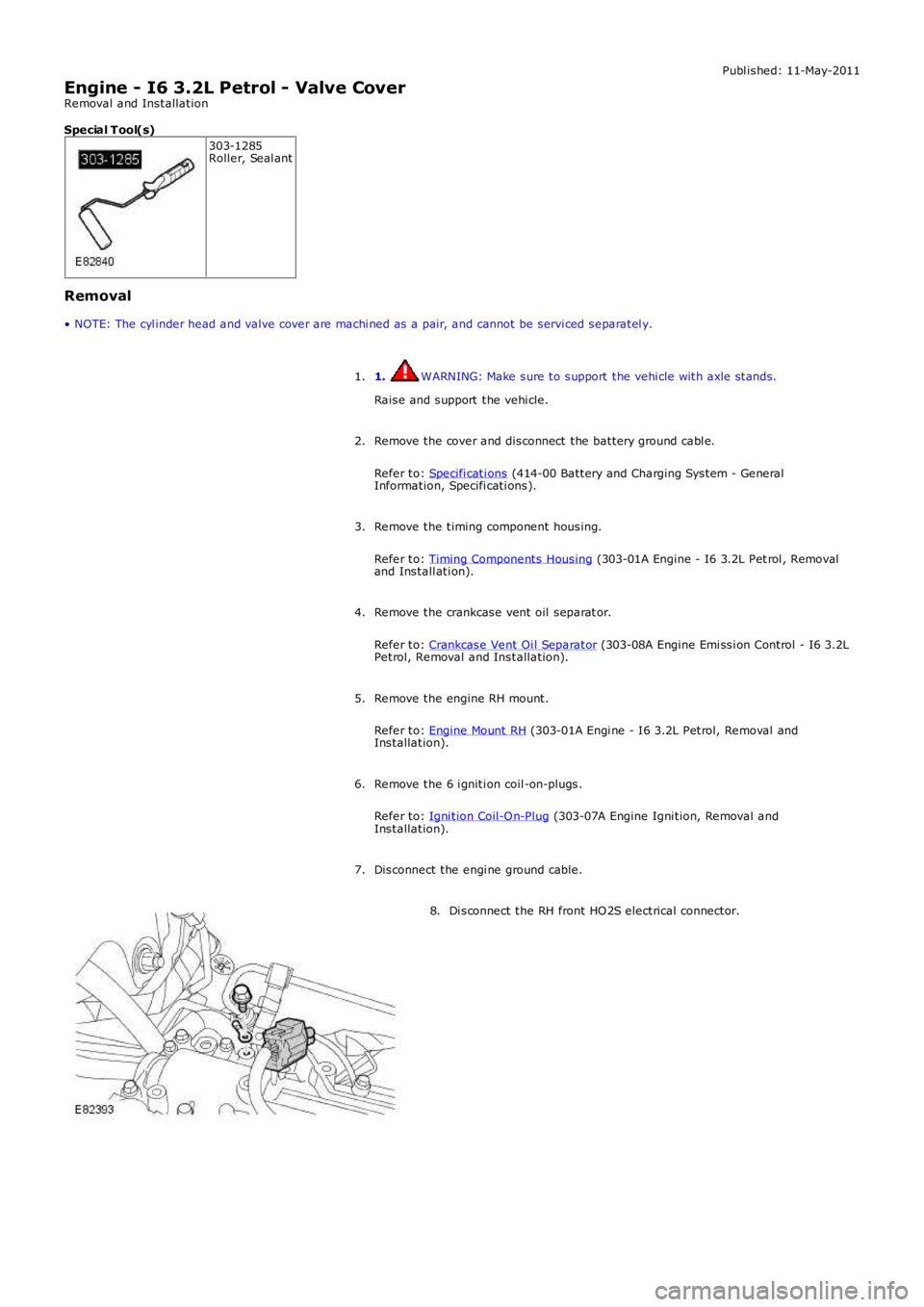
Special T ool(s) 303-1285
Roller, Seal ant
Removal
• NOTE: The cyl inder head and valve cover are machi ned as a pair, and cannot be serv i ced separatel y.
1. WARNING: Make sure to support the vehi cle with axle stands.
Raise and support the vehi cle.
1.
Remove the cover and disconnect the battery ground cabl e.
Refer to: Specifi cati ons (414-00 Battery and Charging System - General
Information, Specifi cati ons).
2.
Remove the timing component housing.
Refer to: Timing Components Housing (303-01A Engine - I6 3.2L Pet rol , Removal
and Install ati on).
3.
Remove the crankcase vent oil separat or.
Refer to: Crankcase Vent Oi l Separator (303-08A Engine Emi ssi on Control - I6 3.2L
Petrol, Removal and Installation).
4.
Remove the engine RH mount.
Refer to: Engine Mount RH (303-01A Engi ne - I6 3.2L Petrol, Removal and
Installation).
5.
Remove the 6 i gniti on coil -on-plugs.
Refer to: Igni tion Coil-On-Plug (303-07A Engine Igni tion, Removal and
Installation).
6.
Disconnect the engi ne ground cable.
7. Di sconnect the RH front HO2S electrical connector.
8.
Page 667 of 3229
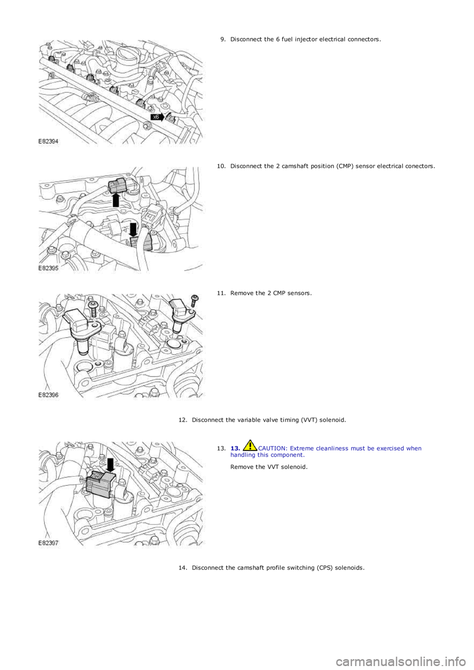
Di sconnect the 6 fuel inject or el ectri cal connectors.
9. Di sconnect the 2 camshaft positi on (CMP) sensor el ectrical conectors.
10. Remove t he 2 CMP sensors.
11.
Disconnect the variable val ve ti ming (VVT) solenoi d.
12. 13. CAUTION: Extreme cleanli ness must be exerci sed when
handling this component.
Remove t he VVT sol enoid.
13.
Disconnect the camshaft profil e switching (CPS) solenoi ds.
14.
Page 668 of 3229
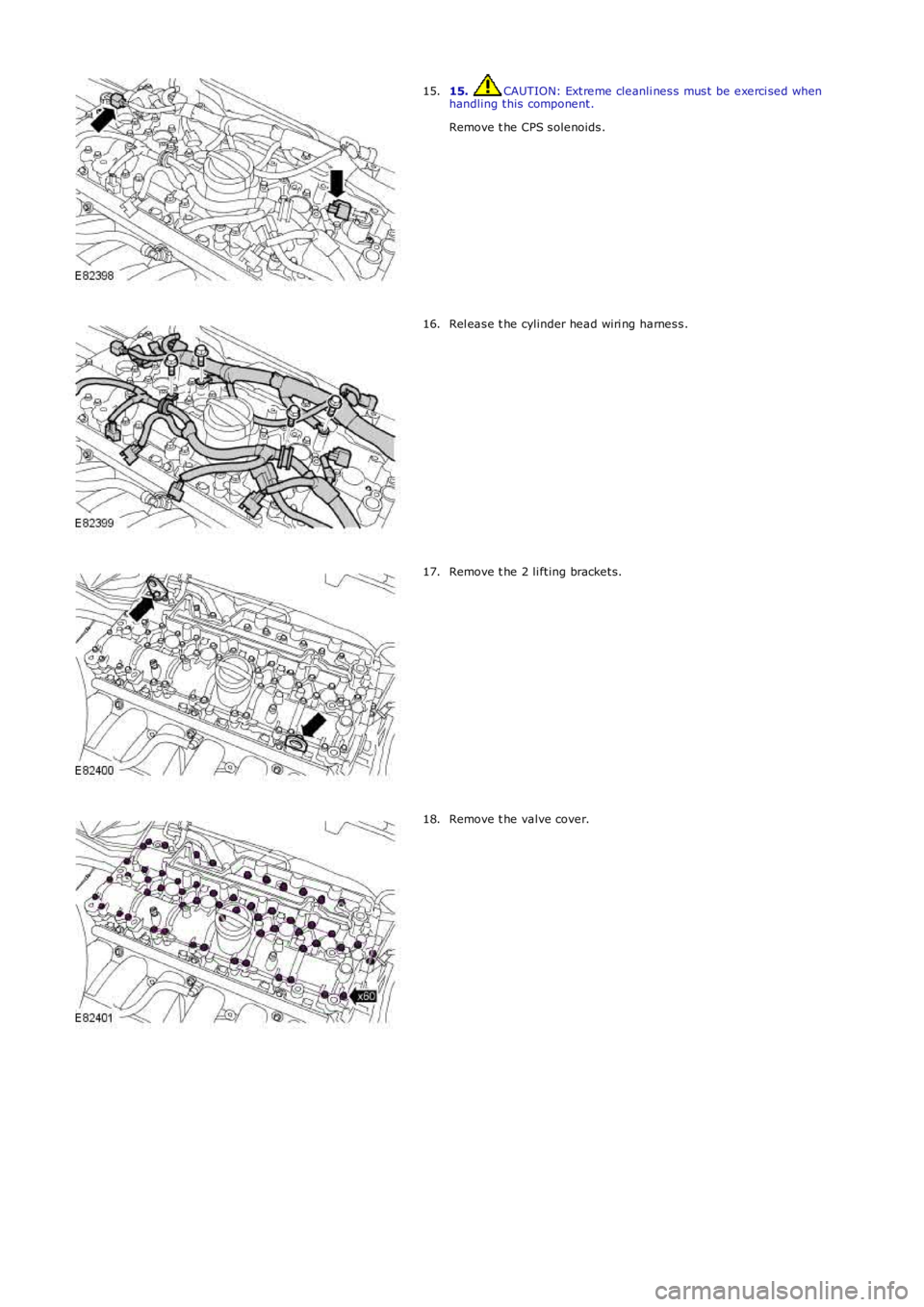
15. CAUTION: Extreme cleanli ness must be exerci sed when
handling this component.
Remove t he CPS solenoids.
15. Rel ease t he cylinder head wiri ng harness.
16. Remove t he 2 li fting brackets.
17. Remove t he valve cover.
18.
Page 669 of 3229
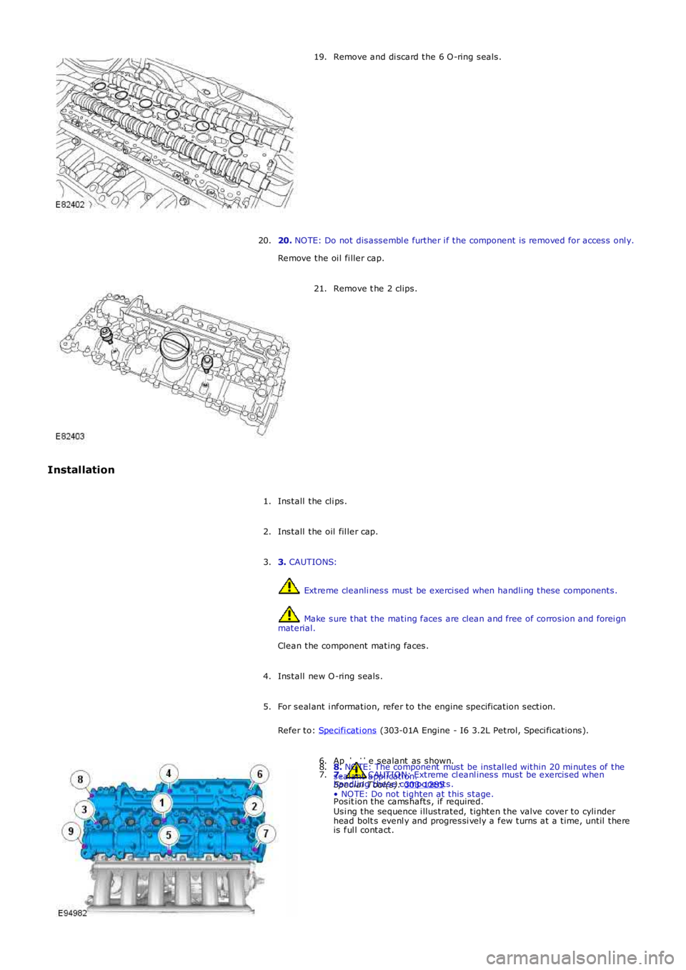
Remove and di scard the 6 O-ring seals.
19.
20. NOTE: Do not disassembl e further i f the component is removed for access onl y.
Remove the oi l fi ller cap.
20. Remove t he 2 clips.
21.
Installation Install the cli ps.
1.
Install the oil fil ler cap.
2.
3. CAUTIONS: Extreme cleanli ness must be exerci sed when handli ng these components.
Make sure that the mating faces are clean and free of corrosion and forei gn
material.
Clean the component mating faces.
3.
Install new O-ring seals.
4.
For seal ant i nformation, refer to the engine specification secti on.
Refer to: Specifi cati ons (303-01A Engine - I6 3.2L Petrol, Speci fications).
5. Apply the sealant as shown.
Special T ool(s): 303-1285 6.
7. CAUTION: Extreme cl eanl iness must be exercised when
handling these components.
Posit ion the camshafts, if required.
7. 8.
NOTE: The component must be instal led within 20 mi nutes of the
sealant appli cati on.
• NOTE: Do not tighten at this stage.
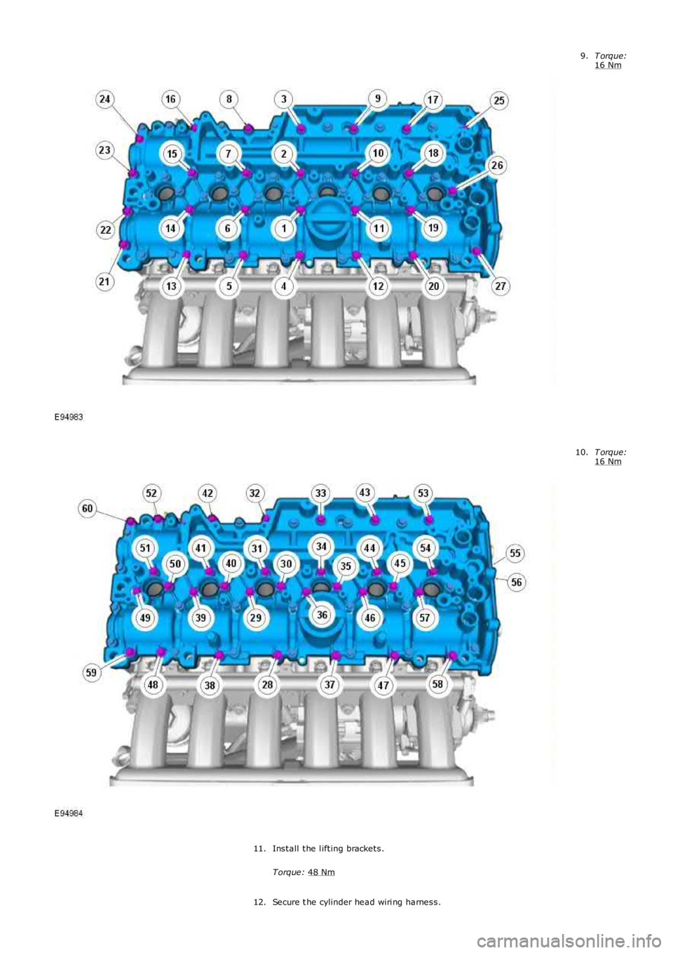
Usi ng the sequence i llustrated, tighten the valve cover to cyli nder
head bolt s evenl y and progressi vely a few turns at a time, until there
is ful l contact.
8.
Page 670 of 3229
T orque:
16 Nm 9.
T orque:
16 Nm 10.
Install the l ifting brackets.
Torque: 48 Nm 11.
Secure t he cylinder head wiri ng harness.
12.
Trending: coolant reservoir, OBD port, length, washer fluid, tyre pressure, headlamp, door lock
