LAND ROVER FRELANDER 2 2006 Repair Manual
FRELANDER 2 2006
LAND ROVER
LAND ROVER
https://www.carmanualsonline.info/img/64/57251/w960_57251-0.png
LAND ROVER FRELANDER 2 2006 Repair Manual
Trending: windshield wipers, reset, inflation pressure, fuel type, oil dipstick, OBD port, power steering
Page 631 of 3229
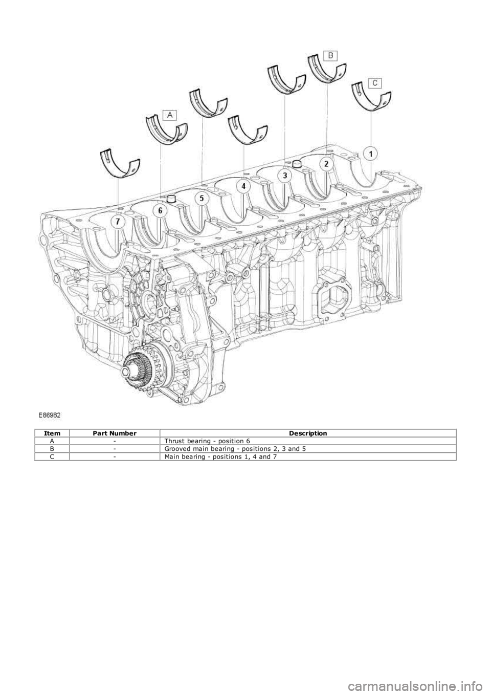
ItemPart NumberDescriptionA-Thrus t bearing - posit ion 6B-Grooved main bearing - pos it ions 2, 3 and 5C-Main bearing - pos it ions 1, 4 and 7
Page 632 of 3229
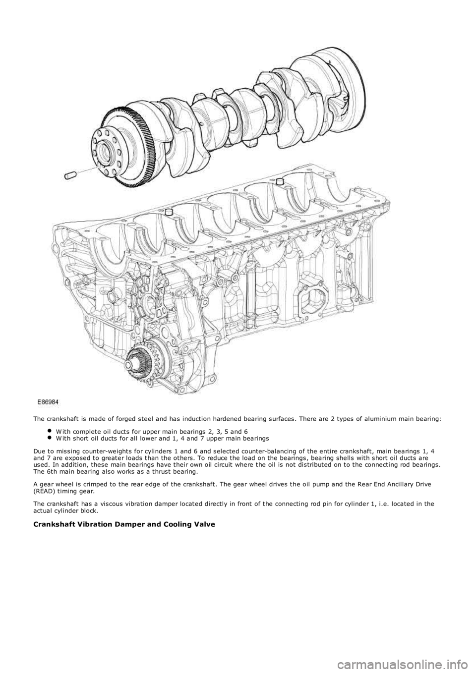
The crankshaft is made of forged s teel and has induction hardened bearing s urfaces . There are 2 types of aluminium main bearing:
W it h complet e oil duct s for upper main bearings 2, 3, 5 and 6W it h short oil ducts for all lower and 1, 4 and 7 upper main bearings
Due t o mis s ing count er-weight s for cylinders 1 and 6 and s elected count er-balancing of the entire crankshaft , main bearings 1, 4and 7 are exposed t o great er loads t han the ot hers. To reduce t he load on the bearings , bearing shells wit h s hort oil duct s areus ed. In addit ion, these main bearings have t heir own oil circuit where t he oil is not dis tribut ed on t o t he connecting rod bearings.The 6t h main bearing als o works as a t hrus t bearing.
A gear wheel is crimped to t he rear edge of the crankshaft . The gear wheel drives t he oil pump and the Rear End Ancillary Drive(READ) t iming gear.
The crankshaft has a vis cous vibration damper locat ed directly in front of t he connecting rod pin for cylinder 1, i.e. located in theact ual cylinder block.
Crankshaft Vibration Damper and Cooling Valve
Page 633 of 3229
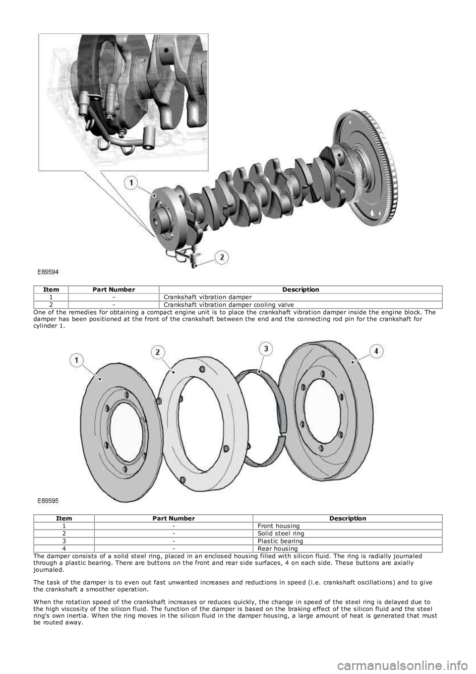
ItemPart NumberDescription1-Cranks haft vibration damper2-Cranks haft vibration damper cooling valveOne of t he remedies for obt aining a compact engine unit is to place the crankshaft vibrat ion damper inside t he engine block. Thedamper has been pos itioned at t he front of the crankshaft bet ween t he end and t he connect ing rod pin for t he crankshaft forcylinder 1.
ItemPart NumberDescription1-Front hous ing2-Solid s t eel ring3-Plas t ic bearing4-Rear hous ingThe damper consis ts of a s olid st eel ring, placed in an enclos ed hous ing filled wit h s ilicon fluid. The ring is radially journaledthrough a plas t ic bearing. There are but t ons on t he front and rear s ide s urfaces, 4 on each side. These but tons are axiallyjournaled.
The t ask of the damper is t o even out fast unwanted increases and reduct ions in speed (i.e. cranks haft os cillat ions ) and t o givethe crankshaft a s moot her operat ion.
W hen the rotat ion speed of the crankshaft increas es or reduces quickly, t he change in s peed of t he st eel ring is delayed due tothe high vis cos ity of t he silicon fluid. The funct ion of the damper is bas ed on t he braking effect of t he s ilicon fluid and the s t eelring's own inert ia. W hen the ring moves in t he silicon fluid in t he damper hous ing, a large amount of heat is generated t hat mus tbe routed away.
Page 634 of 3229
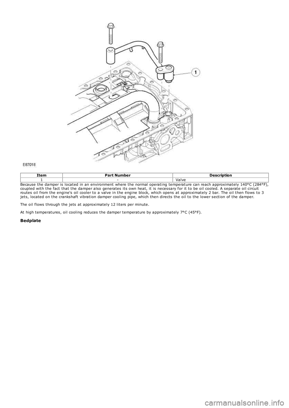
ItemPart NumberDescription1-ValveBecause the damper is locat ed in an environment where t he normal operat ing temperat ure can reach approximat ely 140°C (284°F),coupled wit h t he fact that t he damper also generates it s own heat, it is neces sary for it t o be oil cooled. A s eparat e oil circuitroutes oil from the engine's oil cooler t o a valve in t he engine block, which opens at approximat ely 2 bar. The oil t hen flows t o 3jet s, located on t he cranks haft vibrat ion damper cooling pipe, which then directs the oil t o the lower s ect ion of t he damper.
The oil flows t hrough the jets at approximately 12 lit ers per minute.
At high t emperat ures , oil cooling reduces t he damper t emperat ure by approximat ely 7°C (45°F).
Bedplate
Page 635 of 3229
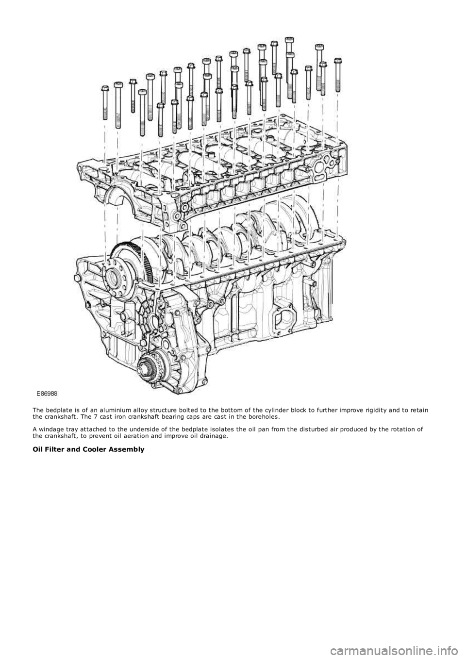
The bedplat e is of an aluminium alloy s t ruct ure bolt ed t o t he bot t om of the cylinder block t o furt her improve rigidit y and t o retainthe crankshaft . The 7 cas t iron cranks haft bearing caps are cas t in t he boreholes .
A windage t ray at t ached to the underside of t he bedplat e isolates t he oil pan from the dis t urbed air produced by t he rotat ion ofthe crankshaft , to prevent oil aeration and improve oil drainage.
Oil Filter and Cooler Assembly
Page 636 of 3229
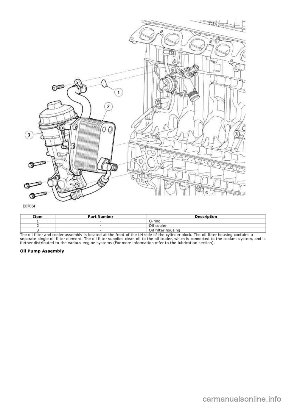
ItemPart NumberDescription1-O-ring2-Oil cooler3-Oil filt er housingThe oil filter and cooler ass embly is located at the front of the LH s ide of t he cylinder block. The oil filt er housing cont ains aseparat e single oil filt er element . The oil filter supplies clean oil t o t he oil cooler, which is connect ed t o t he coolant s yst em, and isfurther dist ribut ed to the various engine sys tems (For more informat ion refer t o t he lubrication s ect ion).
Oil Pump Assembly
Page 637 of 3229
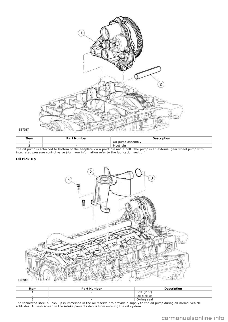
ItemPart NumberDescription1-Oil pump as sembly2-Pivot pinThe oil pump is at t ached t o bot tom of t he bedplat e via a pivot pin and a bolt . The pump is an external gear wheel pump wit hint egrat ed pres sure cont rol valve (for more informat ion refer t o t he lubricat ion s ect ion).
Oil Pick-up
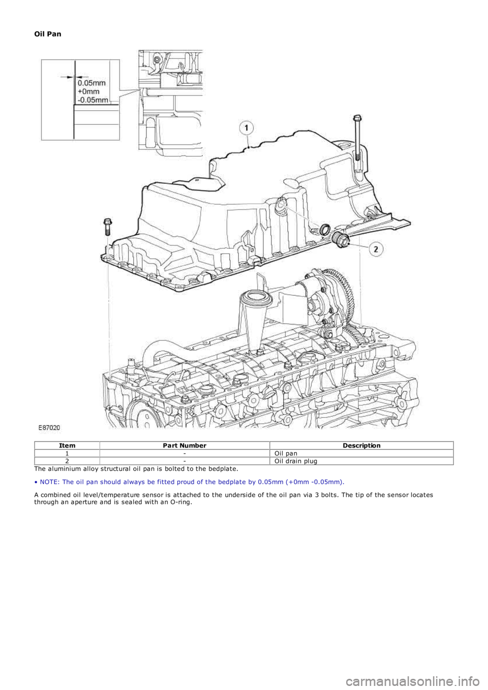
ItemPart NumberDescription1-Bolt (2 of)2-O il pick-up3-O -ring s ealThe fabricat ed st eel oil pick-up is immersed in the oil reservoir t o provide a s upply t o t he oil pump during all normal vehicleat t it udes . A mesh screen in the intake prevent s debris from entering t he oil s yst em.
Page 638 of 3229
Oil Pan
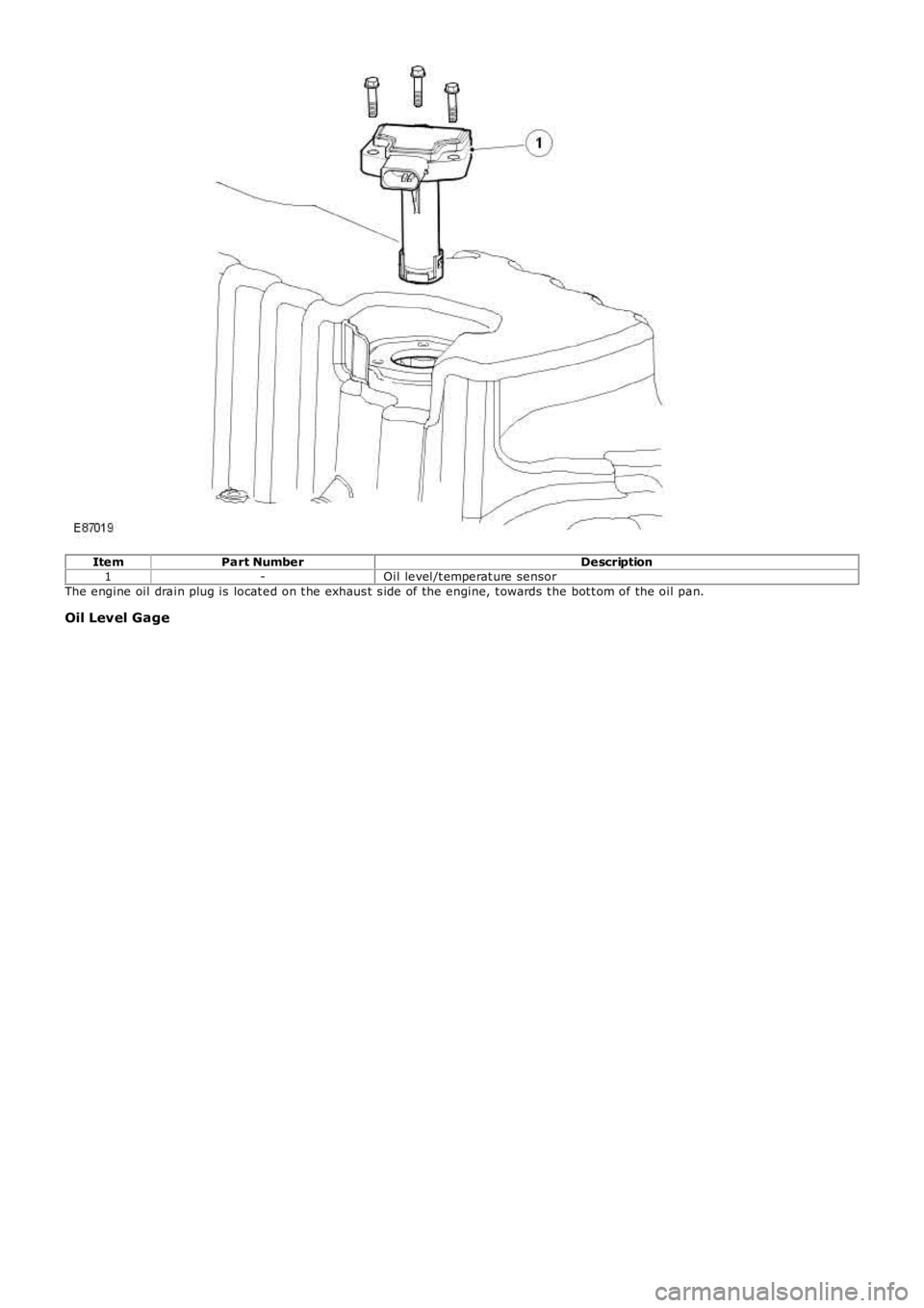
ItemPart NumberDescription1-Oil pan2-Oil drain plugThe aluminium alloy s truct ural oil pan is bolted t o t he bedplat e.
• NOTE: The oil pan s hould always be fit ted proud of t he bedplat e by 0.05mm (+0mm -0.05mm).
A combined oil level/t emperat ure sensor is at t ached to t he underside of t he oil pan via 3 bolt s. The tip of the s ens or locat esthrough an aperture and is s ealed wit h an O-ring.
Page 639 of 3229
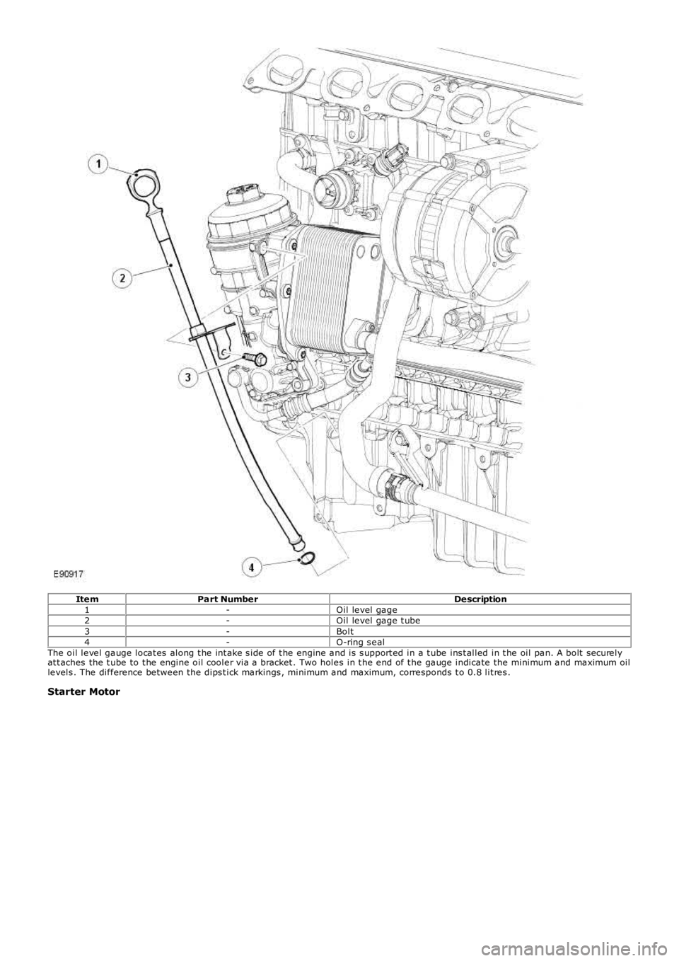
ItemPart NumberDescription1-Oil level/t emperat ure sensorThe engine oil drain plug is locat ed on t he exhaus t s ide of the engine, t owards t he bot t om of the oil pan.
Oil Level Gage
Page 640 of 3229
ItemPart NumberDescription1-Oil level gage2-Oil level gage t ube3-Bolt4-O-ring s ealThe oil level gauge locat es along t he int ake s ide of t he engine and is s upport ed in a t ube ins t alled in t he oil pan. A bolt s ecurelyat t aches the t ube to t he engine oil cooler via a bracket . Two holes in t he end of t he gauge indicate the minimum and maximum oillevels . The difference between the dips t ick markings , minimum and maximum, corresponds t o 0.8 lit res .
Starter Motor
Trending: fuse chart, ESP, fuel pressure, width, checking oil, jump start, overheating
