LEXUS LS430 2003 Factory Owners Manual
Manufacturer: LEXUS, Model Year: 2003,
Model line: LS430,
Model: LEXUS LS430 2003
Pages: 4500, PDF Size: 87.45 MB
LEXUS LS430 2003 Factory Owners Manual
LS430 2003
LEXUS
LEXUS
https://www.carmanualsonline.info/img/36/57050/w960_57050-0.png
LEXUS LS430 2003 Factory Owners Manual
Trending: service interval, brake light, oil level, manual transmission, Diagram ac amplifier, wiring diagram, Ecm
Page 91 of 4500
NG: CHECK FOR SHORT IN ALL HARNESS AND CONNECTOR CONNECTED TO FUSE
AND REPLACE FUSE
OK: Go to next step
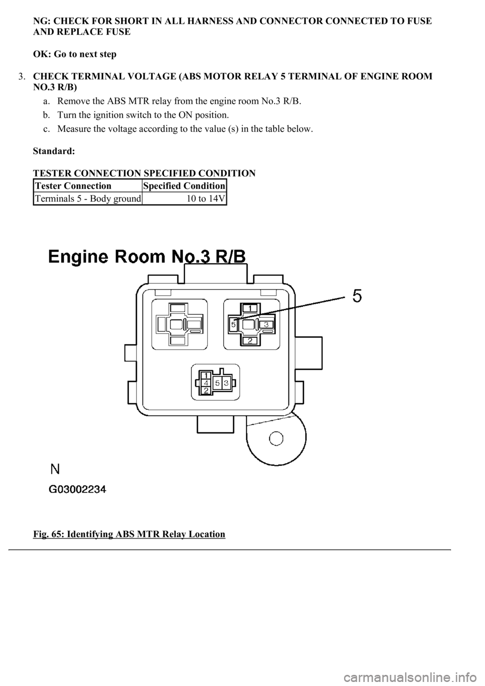
3.CHECK TERMINAL VOLTAGE (ABS MOTOR RELAY 5 TERMINAL OF ENGINE ROOM
NO.3 R/B)
a. Remove the ABS MTR relay from the engine room No.3 R/B.
b. Turn the ignition switch to the ON position.
c. Measure the voltage according to the value (s) in the table below.
Standard:
TESTER CONNECTION SPECIFIED CONDITION
Fig. 65: Identifying ABS MTR Relay Location
Tester ConnectionSpecified Condition
Terminals 5 - Body ground10 to 14V
Page 92 of 4500
Courtesy of TOYOTA MOTOR SALES, U.S.A., INC.
NG: REPAIR OR REPLACE HARNESS OR CONNECTOR
OK: Go to next step
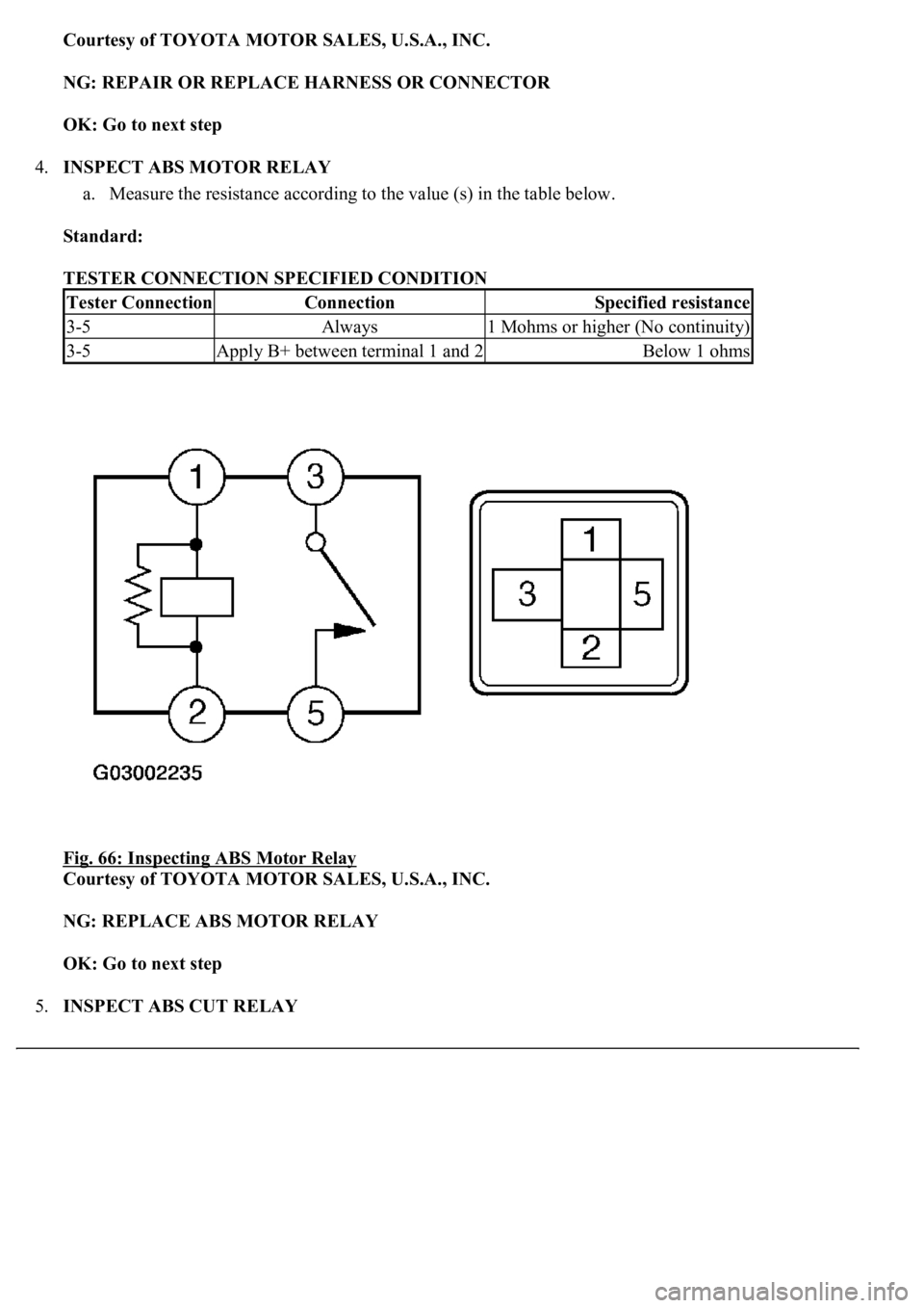
4.INSPECT ABS MOTOR RELAY
a. Measure the resistance according to the value (s) in the table below.
Standard:
TESTER CONNECTION SPECIFIED CONDITION
Fig. 66: Inspecting ABS Motor Relay
Courtesy of TOYOTA MOTOR SALES, U.S.A., INC.
NG: REPLACE ABS MOTOR RELAY
OK: Go to next step
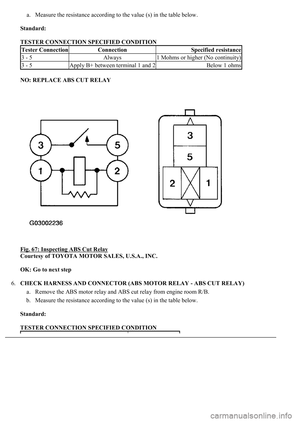
5.INSPECT ABS CUT RELAY
Tester ConnectionConnectionSpecified resistance
3-5Always1 Mohms or higher (No continuity)
3-5Apply B+ between terminal 1 and 2Below 1 ohms
Page 93 of 4500
a. Measure the resistance according to the value (s) in the table below.
Standard:
TESTER CONNECTION SPECIFIED CONDITION
NO: REPLACE ABS CUT RELAY
Fig. 67: Inspecting ABS Cut Relay
Courtesy of TOYOTA MOTOR SALES, U.S.A., INC.
OK: Go to next step
6.CHECK HARNESS AND CONNECTOR (ABS MOTOR RELAY - ABS CUT RELAY)
a. Remove the ABS motor relay and ABS cut relay from engine room R/B.
b. Measure the resistance according to the value (s) in the table below.
Standard:
TESTER CONNECTION SPECIFIED CONDITION
Tester ConnectionConnectionSpecified resistance
3 - 5Always1 Mohms or higher (No continuity)
3 - 5Apply B+ between terminal 1 and 2Below 1 ohms
Page 94 of 4500
NG: REPAIR OR REPLACE HARNESS OR CONNECTOR
OK: Go to next step
7.CHECK HARNESS AND CONNECTOR (ABS MOTOR RELAY - SKID CONTROL ECU)
a. Disconnect the skid control ECU connector.
b. Measure the resistance according to the value (s) in the table below.
Standard:
TESTER CONNECTION SPECIFIED CONDITION
c. Measure the resistance accordin
g to the value (s) in the table below.
Tester ConnectionSpecified Condition
5 (ABS MOTOR Relay) - 3 (ABS cut relay)Below 1 ohms
Tester ConnectionSpecified Condition
S42-2 (BM) - 3 (Engine room R/B)Below 1 ohms
Page 95 of 4500
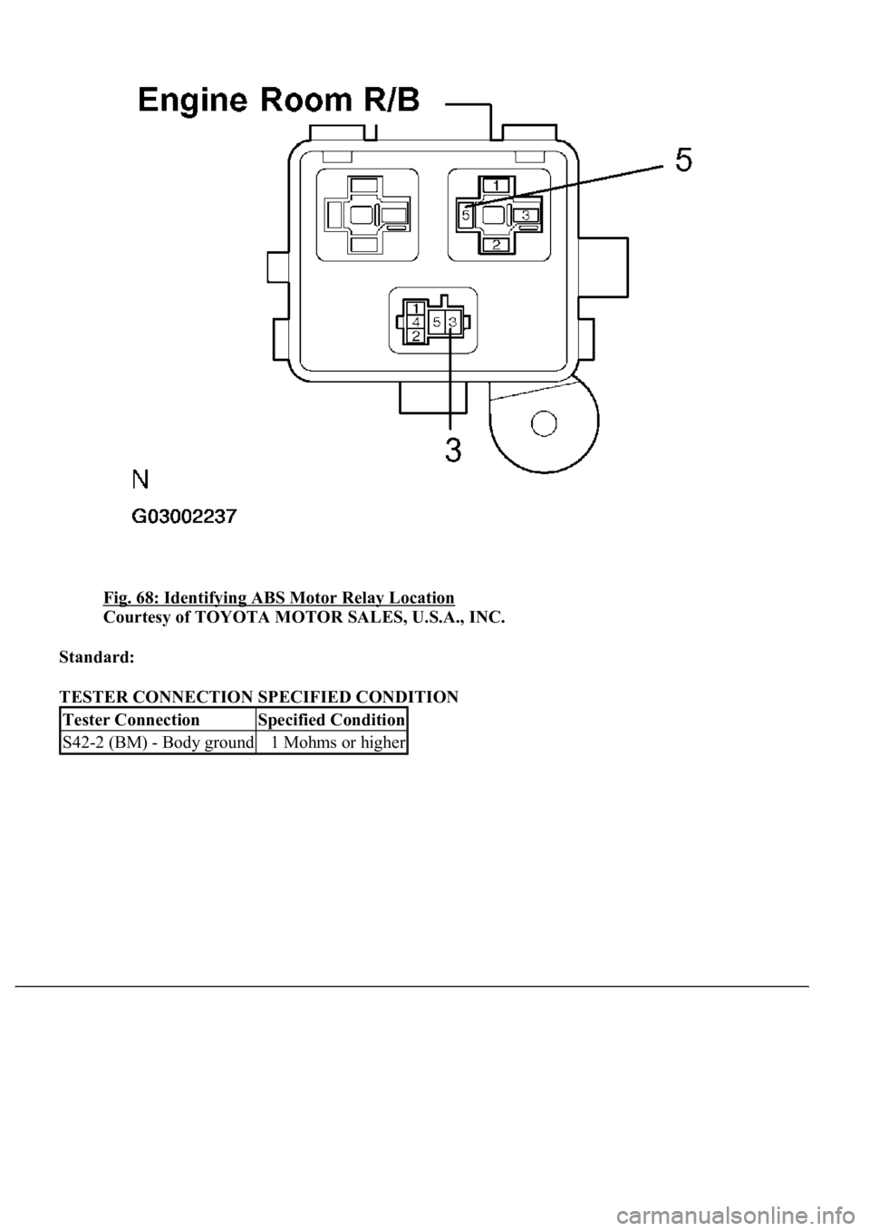
Fig. 68: Identifying ABS Motor Relay Location
Courtesy of TOYOTA MOTOR SALES, U.S.A., INC.
Standard:
TESTER CONNECTION SPECIFIED CONDITION
Tester ConnectionSpecified Condition
S42-2 (BM) - Body ground1 Mohms or higher
Page 96 of 4500
Page 97 of 4500
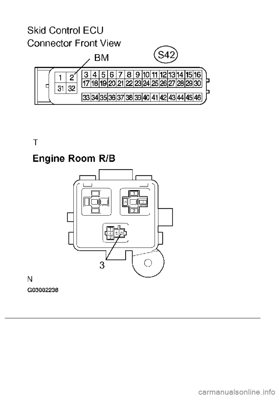
Fig. 69: Identifying Skid Control ECU Connector Terminals
Courtesy of TOYOTA MOTOR SALES, U.S.A., INC.
NG: REPAIR OR REPLACE HARNESS OR CONNECTOR
OK: REPLACE ABS & TRACTION ACTUATOR ASSY (SEE REPLACEMENT
)
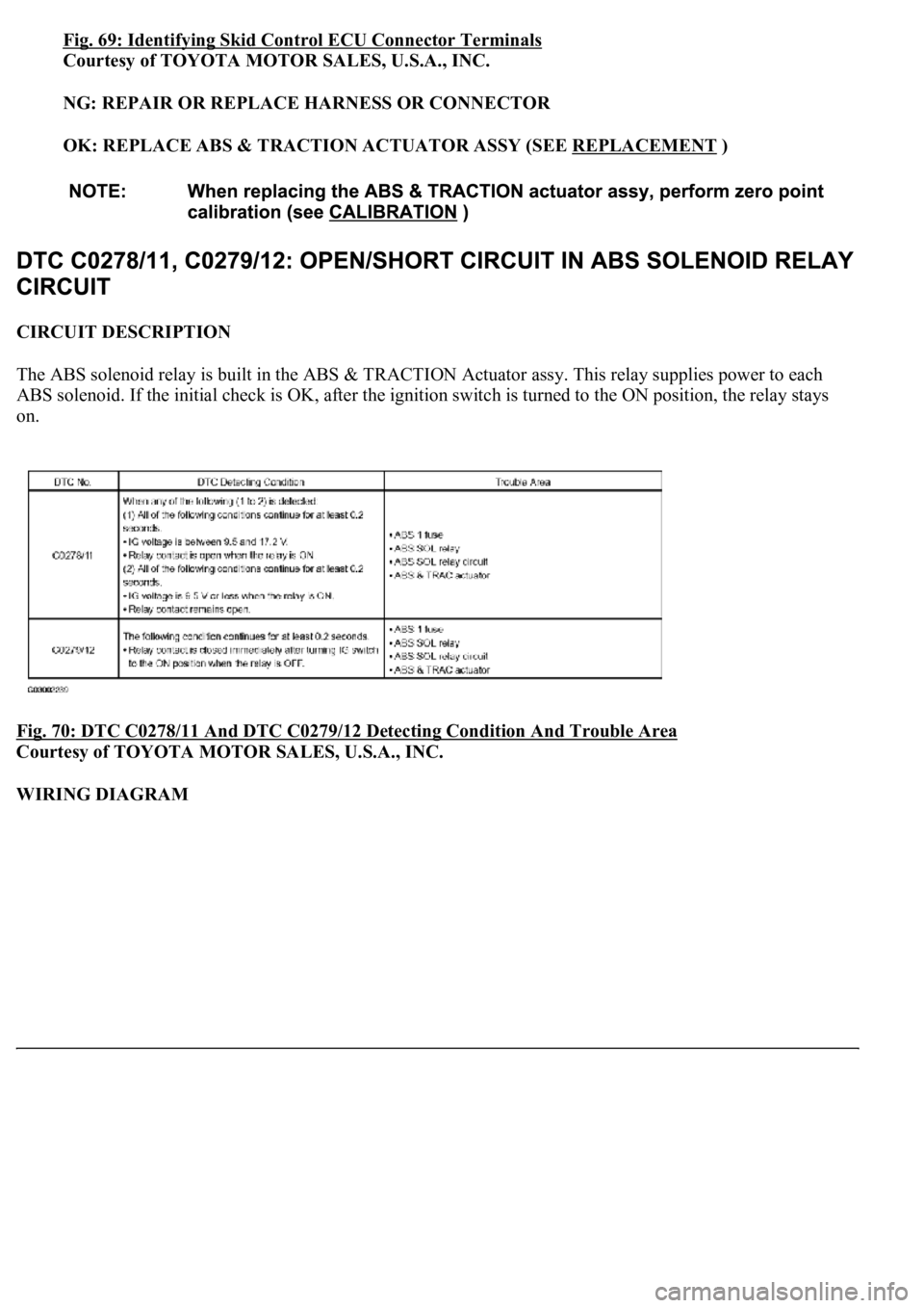
CIRCUIT DESCRIPTION
The ABS solenoid relay is built in the ABS & TRACTION Actuator assy. This relay supplies power to each
ABS solenoid. If the initial check is OK, after the ignition switch is turned to the ON position, the relay stays
on.
Fig. 70: DTC C0278/11 And DTC C0279/12 Detecting Condition And Trouble Area
Courtesy of TOYOTA MOTOR SALES, U.S.A., INC.
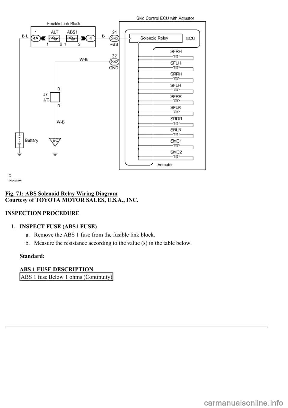
WIRING DIAGRAM
Page 98 of 4500
Fig. 71: ABS Solenoid Relay Wiring Diagram
Courtesy of TOYOTA MOTOR SALES, U.S.A., INC.
INSPECTION PROCEDURE
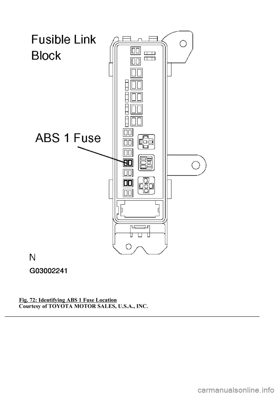
1.INSPECT FUSE (ABS1 FUSE)
a. Remove the ABS 1 fuse from the fusible link block.
b. Measure the resistance according to the value (s) in the table below.
Standard:
ABS 1 FUSE DESCRIPTION
ABS 1 fuseBelow 1 ohms (Continuity)
Page 99 of 4500
Fig. 72: Identifying ABS 1 Fuse Location
Courtesy of TOYOTA MOTOR SALES, U.S.A., INC.
Page 100 of 4500
NG: CHECK FOR SHORT IN ALL HARNESS AND CONNECTOR CONNECTED TO FUSE
AND REPLACE FUSE
OK: Go to next step
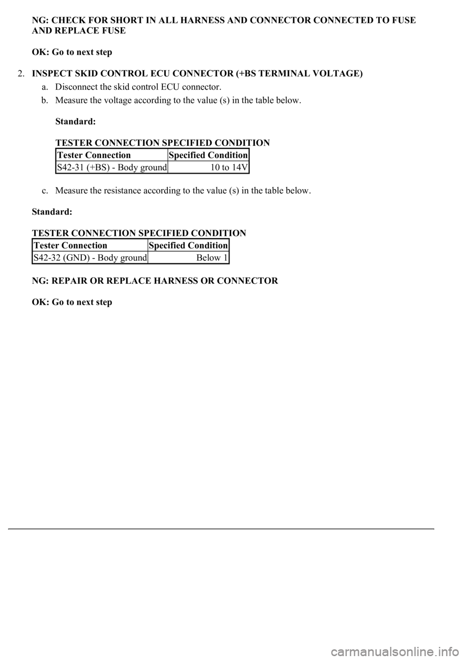
2.INSPECT SKID CONTROL ECU CONNECTOR (+BS TERMINAL VOLTAGE)
a. Disconnect the skid control ECU connector.
b. Measure the voltage according to the value (s) in the table below.
Standard:
TESTER CONNECTION SPECIFIED CONDITION
c. Measure the resistance according to the value (s) in the table below.
Standard:
TESTER CONNECTION SPECIFIED CONDITION
NG: REPAIR OR REPLACE HARNESS OR CONNECTOR
OK: Go to next step
Tester ConnectionSpecified Condition
S42-31 (+BS) - Body ground10 to 14V
Tester ConnectionSpecified Condition
S42-32 (GND) - Body groundBelow 1
Trending: Rear suspension, phone, B2419 bean, warning lights, Ecu, power steering, seat memory
