LEXUS LS430 2003 Factory Manual Online
Manufacturer: LEXUS, Model Year: 2003,
Model line: LS430,
Model: LEXUS LS430 2003
Pages: 4500, PDF Size: 87.45 MB
LEXUS LS430 2003 Factory Manual Online
LS430 2003
LEXUS
LEXUS
https://www.carmanualsonline.info/img/36/57050/w960_57050-0.png
LEXUS LS430 2003 Factory Manual Online
Trending: headlamp, wheel bolts, low beam, fuel cap, battery replacement, air conditioning, back seat removal
Page 81 of 4500
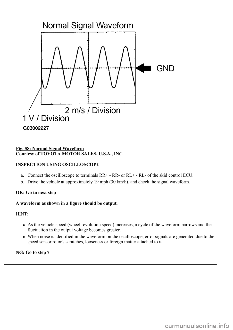
Fig. 58: Normal Signal Waveform
Courtesy of TOYOTA MOTOR SALES, U.S.A., INC.
INSPECTION USING OSCILLOSCOPE
a. Connect the oscilloscope to terminals RR+ - RR- or RL+ - RL- of the skid control ECU.
b. Drive the vehicle at approximately 19 mph (30 km/h), and check the signal waveform.
OK: Go to next step
A waveform as shown in a figure should be output.
HINT:
As the vehicle speed (wheel revolution speed) increases, a cycle of the waveform narrows and the
fluctuation in the output voltage becomes greater.
When noise is identified in the waveform on the oscilloscope, error signals are generated due to the
speed sensor rotor's scratches, looseness or foreign matter attached to it.
NG: Go to step 7
Page 82 of 4500
OK: REPLACE ABS & TRACTION ACTUATOR ASSY (SEE REPLACEMENT )
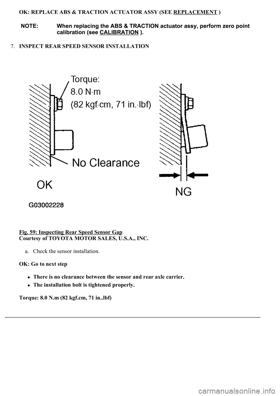
7.INSPECT REAR SPEED SENSOR INSTALLATION
Fig. 59: Inspecting Rear Speed Sensor Gap
Courtesy of TOYOTA MOTOR SALES, U.S.A., INC.
a. Check the sensor installation.
OK: Go to next step
There is no clearance between the sensor and rear axle carrier.
The installation bolt is tightened properly.
Torque: 8.0 N.m (82 kgf.cm, 71 in..lbf)
Page 83 of 4500
NG: REPLACE REAR SPEED SENSOR
OK: REPLACE ABS & TRACTION ACTUATOR ASSY (SEE REPLACEMENT
)
CIRCUIT DESCRIPTION
<0037004b004c0056000300560052004f004800510052004c00470003005700580055005100560003005200510003005a004b0048005100030056004c004a00510044004f0056000300440055004800030055004800460048004c0059004800470003004900
550052005000030057004b0048000300280026003800030044[nd controls the pressure acting on the wheel
c
ylinders to control the braking force.
Page 84 of 4500
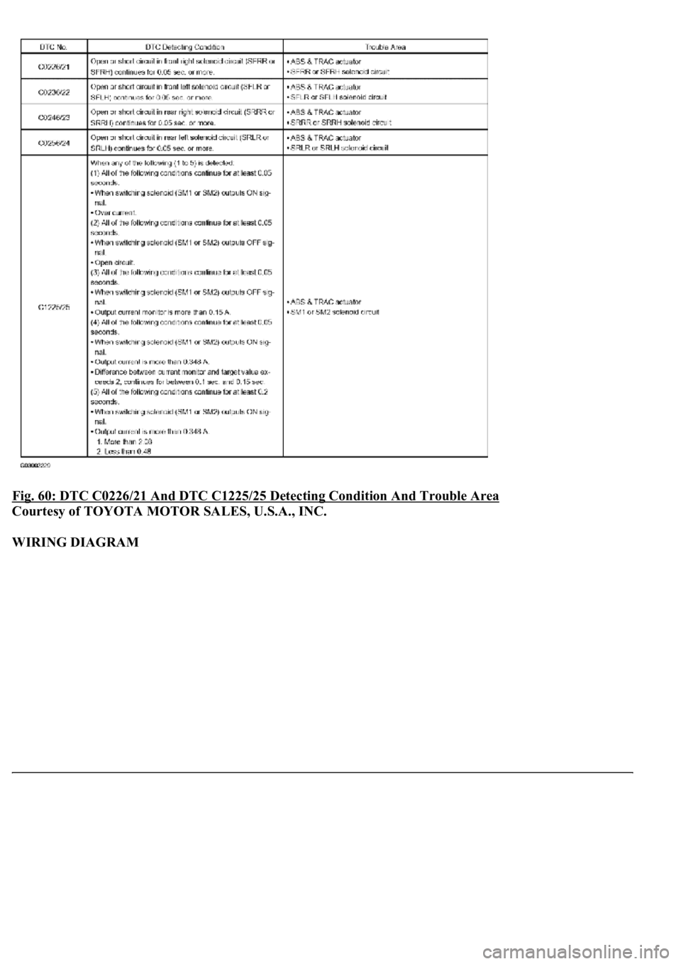
Fig. 60: DTC C0226/21 And DTC C1225/25 Detecting Condition And Trouble Area
Courtesy of TOYOTA MOTOR SALES, U.S.A., INC.
WIRING DIAGRAM
Page 85 of 4500
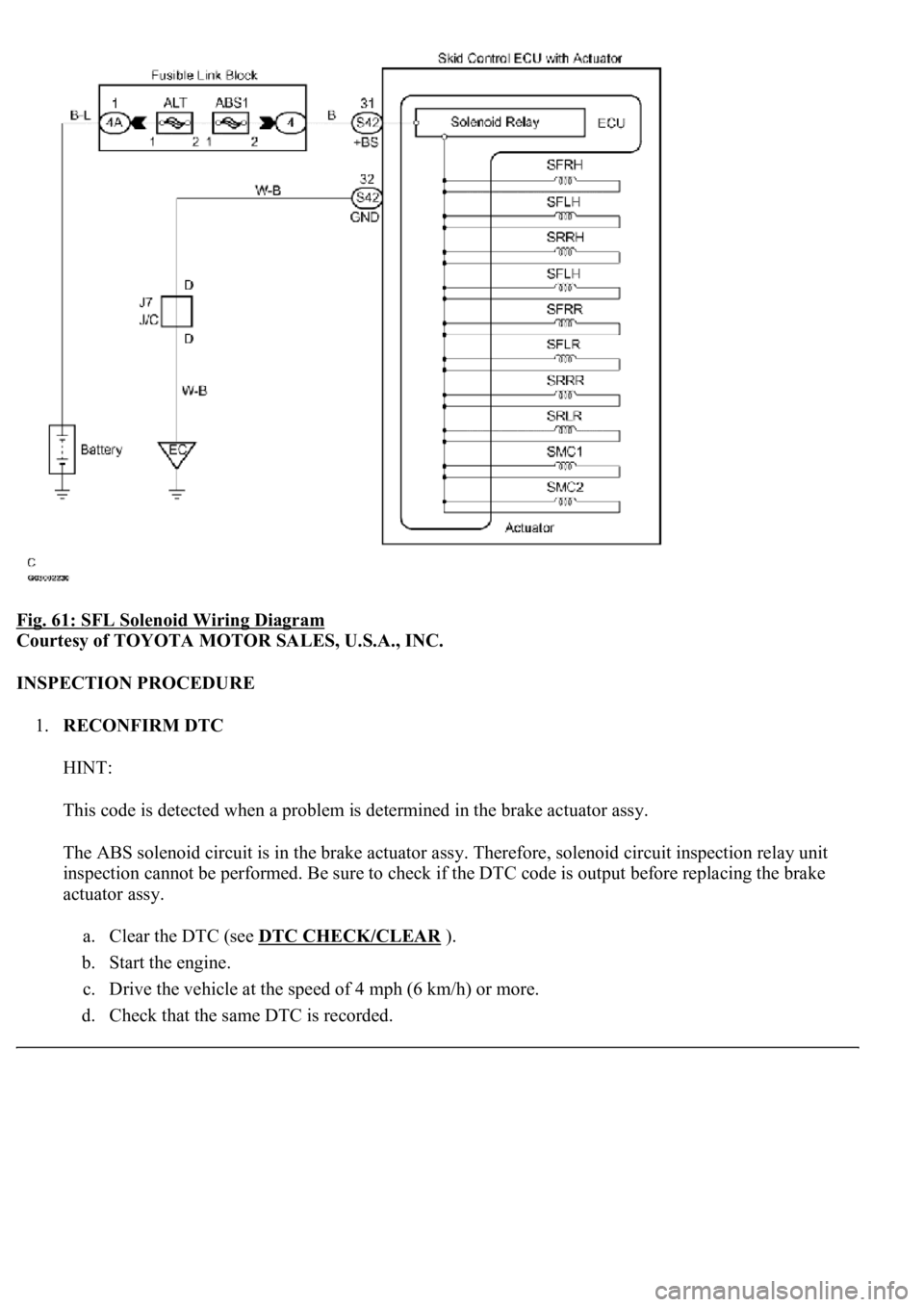
Fig. 61: SFL Solenoid Wiring Diagram
Courtesy of TOYOTA MOTOR SALES, U.S.A., INC.
INSPECTION PROCEDURE
1.RECONFIRM DTC
HINT:
This code is detected when a problem is determined in the brake actuator assy.
The ABS solenoid circuit is in the brake actuator assy. Therefore, solenoid circuit inspection relay unit
inspection cannot be performed. Be sure to check if the DTC code is output before replacing the brake
actuator assy.
a. Clear the DTC (see DTC CHECK/CLEAR
).
b. Start the engine.
c. Drive the vehicle at the speed of 4 mph (6 km/h) or more.
d. Check that the same DTC is recorded.
Page 86 of 4500
OK: Go to next step
The same DTC is recorded.
NG: PROCEED TO NEXT CIRCUIT INSPECTION SHOWN IN PROBLEM SYMPTOMS
TABLE
OK: REPLACE ABS & TRACTION ACTUATOR ASSY (SEE REPLACEMENT
)
CIRCUIT DESCRIPTION
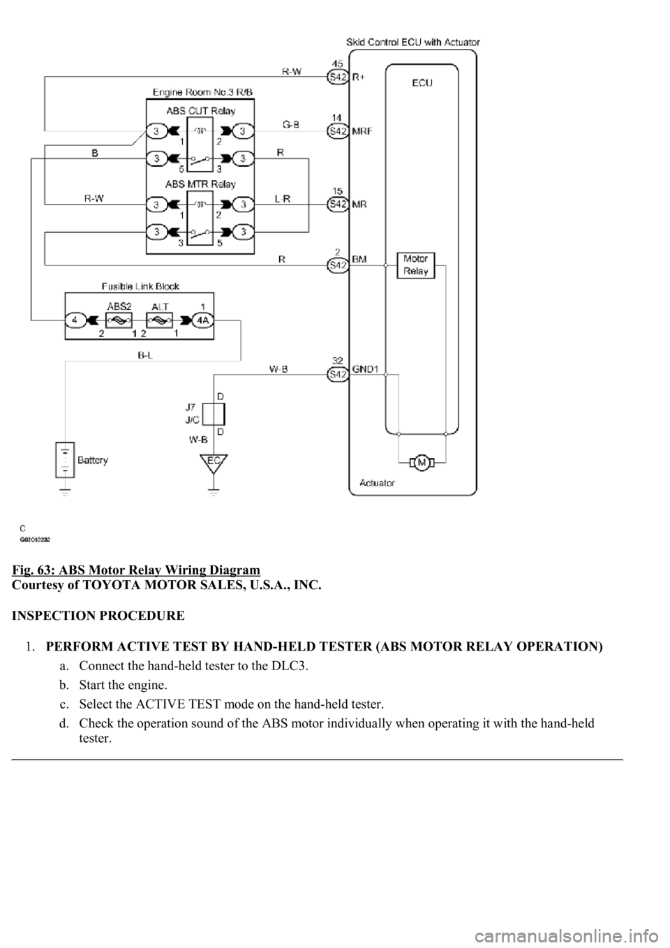
The ABS motor relays consist of 2 relays are included in the engine room No.3 R/B.
The ABS cut relay is turned on after turning the ignition switch to the ON position. If the DTCs in the
ABS pump motor circuit are memorized, the ABS cut relay cuts off the power supply to the ABS motor
relay and performs the fail safe.
While any of the ABS, BA, TRAC and VSC is operating, the skid control ECU (included in the actuator)
<0057005800550051005600030057004b00480003002400250036000300500052005700520055000300550048004f0044005c0003005200510003005700520003005200530048005500440057004800030057004b0048000300440046005700580044005700
52005500030053005800500053000300500052005700520055[.
If the voltage applied to the ABS motor relays (+BM) drops below the condition that detects the DTCs
due to the shorta
ge of the battery or alternator output, the DTCs may be memorized.
Page 87 of 4500
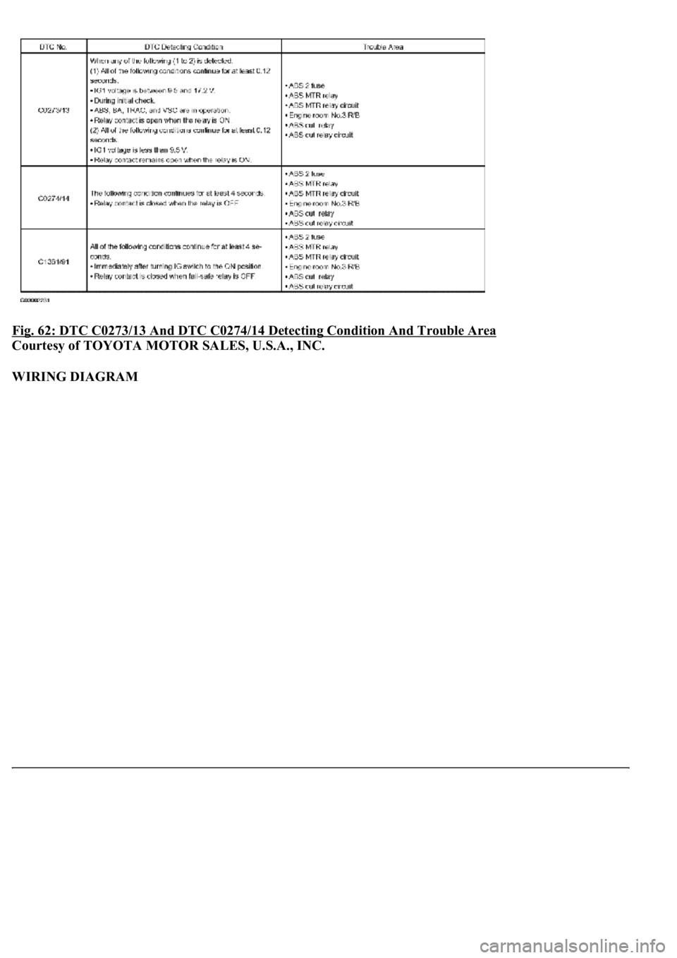
Fig. 62: DTC C0273/13 And DTC C0274/14 Detecting Condition And Trouble Area
Courtesy of TOYOTA MOTOR SALES, U.S.A., INC.
WIRING DIAGRAM
Page 88 of 4500
Fig. 63: ABS Motor Relay Wiring Diagram
Courtesy of TOYOTA MOTOR SALES, U.S.A., INC.
INSPECTION PROCEDURE
1.PERFORM ACTIVE TEST BY HAND-HELD TESTER (ABS MOTOR RELAY OPERATION)
a. Connect the hand-held tester to the DLC3.
b. Start the engine.
c. Select the ACTIVE TEST mode on the hand-held tester.
d. Check the operation sound of the ABS motor individually when operating it with the hand-held
tester.
Page 89 of 4500
VEHICLE CONDITION / TEST DETAILS DESCRIPTION
OK: Go to next step
<0037004b00480003005200530048005500440057004c0052005100030056005200580051004700030052004900030057004b0048000300240025003600030050005200570052005500030056004b00520058004f00470003004500480003004b0048004400
5500470011[
NG: Go to step 2
OK: REPLACE ABS & TRACTION ACTUATOR ASSY (SEE REPLACEMENT
)
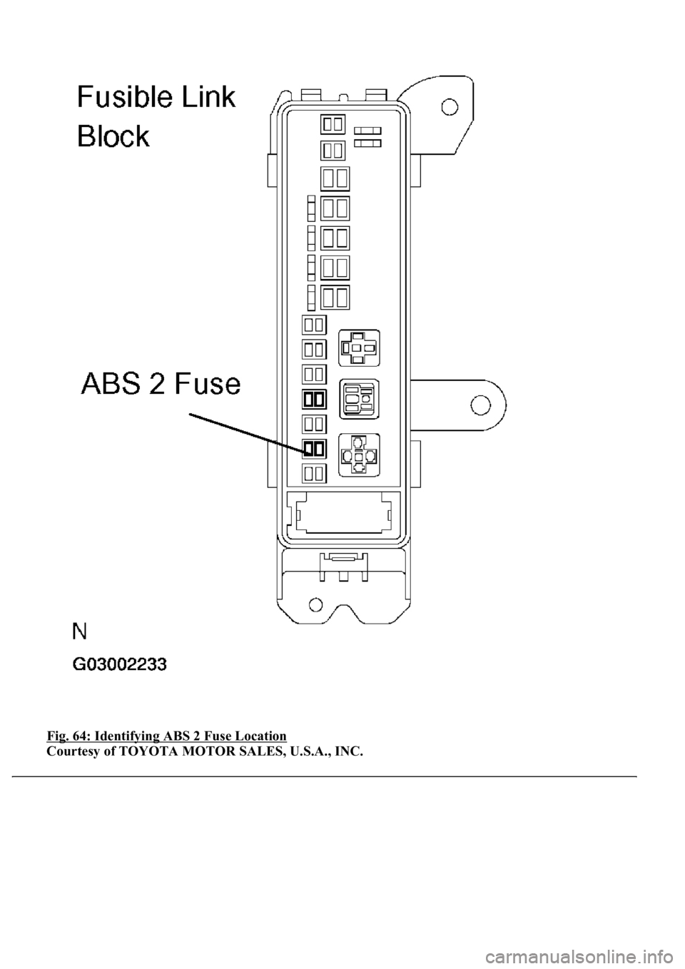
2.INSPECT FUSE (ABS2 FUSE)
a. Remove the ABS 2 fuse from fusible link block.
b. Measure the resistance according to the value (s) in the table below.
Standard:
ABS 2 FUSE DESCRIPTION
ItemVehicle Condition / Test DetailsVehicle Condition / Test Details
ABS MOT RELAYTurns ABS motor relay / ON or OFFON: Motor relay ON
ABS 2 FuseBelow 1 ohms (Continuity)
Page 90 of 4500
Fig. 64: Identifying ABS 2 Fuse Location
Courtesy of TOYOTA MOTOR SALES, U.S.A., INC.
Trending: timing belt, coolant reservoir, remove seats, fuel consumption, set clock, alternator, camshaft service
