LEXUS LS430 2003 Factory Repair Manual
Manufacturer: LEXUS, Model Year: 2003,
Model line: LS430,
Model: LEXUS LS430 2003
Pages: 4500, PDF Size: 87.45 MB
LEXUS LS430 2003 Factory Repair Manual
LS430 2003
LEXUS
LEXUS
https://www.carmanualsonline.info/img/36/57050/w960_57050-0.png
LEXUS LS430 2003 Factory Repair Manual
Trending: cylinder head, navigation system, set clock, TPMS, key battery, evaporator, adding oil
Page 1051 of 4500
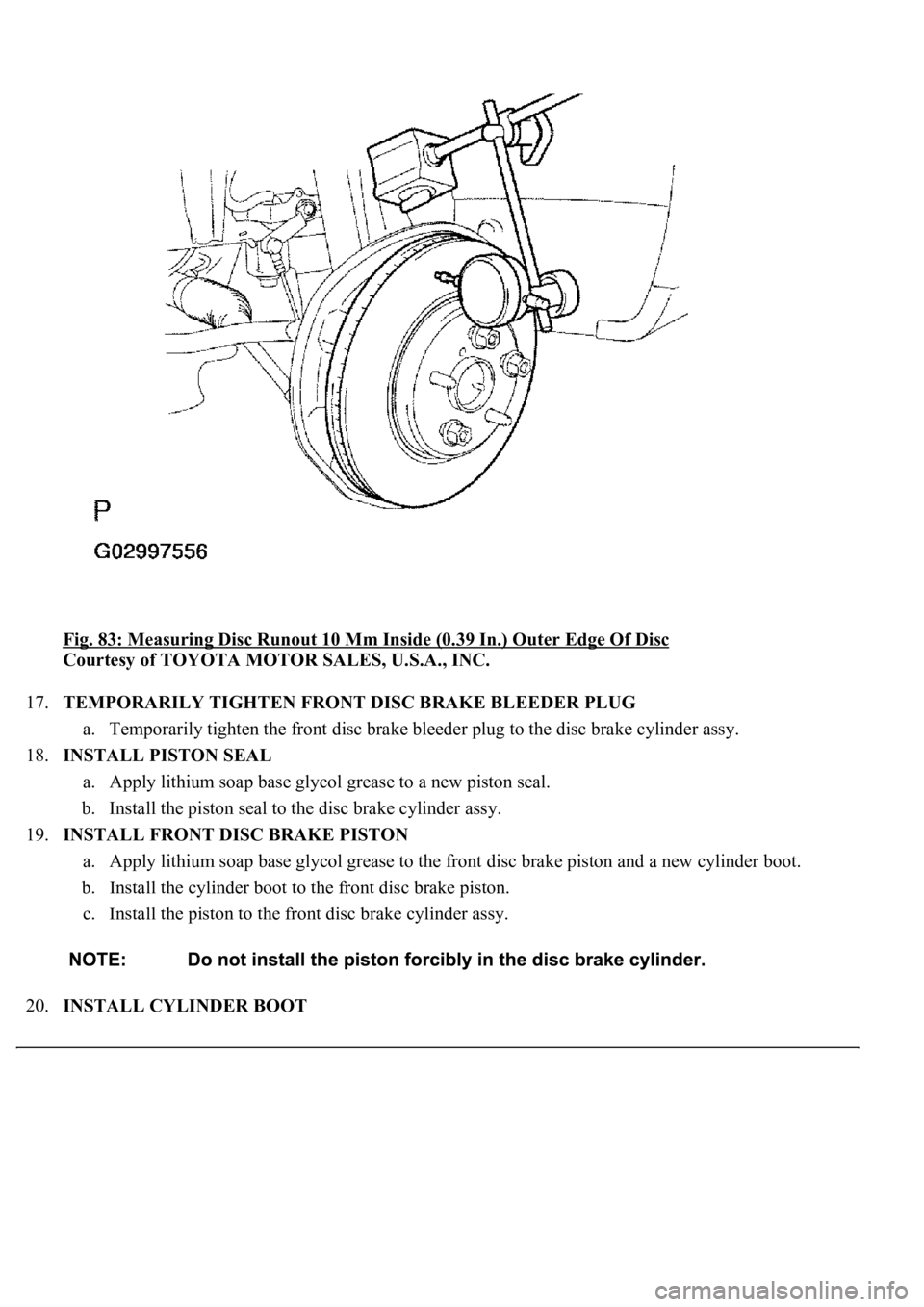
Fig. 83: Measuring Disc Runout 10 Mm Inside (0.39 In.) Outer Edge Of Disc
Courtesy of TOYOTA MOTOR SALES, U.S.A., INC.
17.TEMPORARILY TIGHTEN FRONT DISC BRAKE BLEEDER PLUG
a. Temporarily tighten the front disc brake bleeder plug to the disc brake cylinder assy.
18.INSTALL PISTON SEAL
a. Apply lithium soap base glycol grease to a new piston seal.
b. Install the piston seal to the disc brake cylinder assy.
19.INSTALL FRONT DISC BRAKE PISTON
a. Apply lithium soap base glycol grease to the front disc brake piston and a new cylinder boot.
b. Install the cylinder boot to the front disc brake piston.
c. Install the piston to the front disc brake cylinder assy.
20.INSTALL CYLINDER BOOT
Page 1052 of 4500
a. Install the cylinder boot to the front disc brake cylinder.
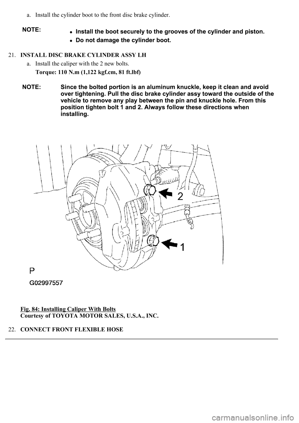
21.INSTALL DISC BRAKE CYLINDER ASSY LH
a. Install the caliper with the 2 new bolts.
Torque: 110 N.m (1,122 kgf.cm, 81 ft.lbf)
Fig. 84: Installing Caliper With Bolts
Courtesy of TOYOTA MOTOR SALES, U.S.A., INC.
22.CONNECT FRONT FLEXIBLE HOSE
Page 1053 of 4500
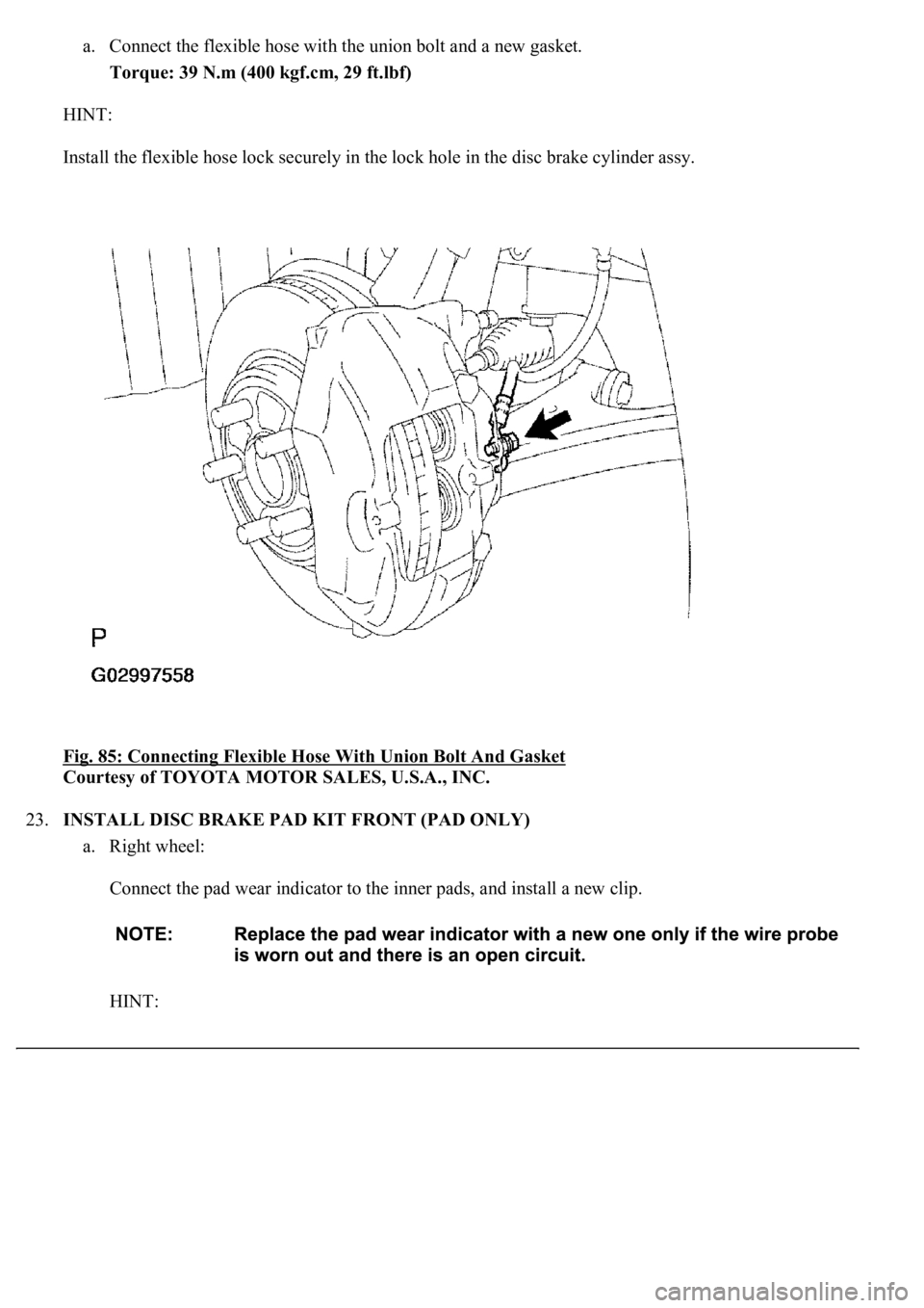
a. Connect the flexible hose with the union bolt and a new gasket.
Torque: 39 N.m (400 kgf.cm, 29 ft.lbf)
HINT:
Install the flexible hose lock securely in the lock hole in the disc brake cylinder assy.
Fig. 85: Connecting Flexible Hose With Union Bolt And Gasket
Courtesy of TOYOTA MOTOR SALES, U.S.A., INC.
23.INSTALL DISC BRAKE PAD KIT FRONT (PAD ONLY)
a. Right wheel:
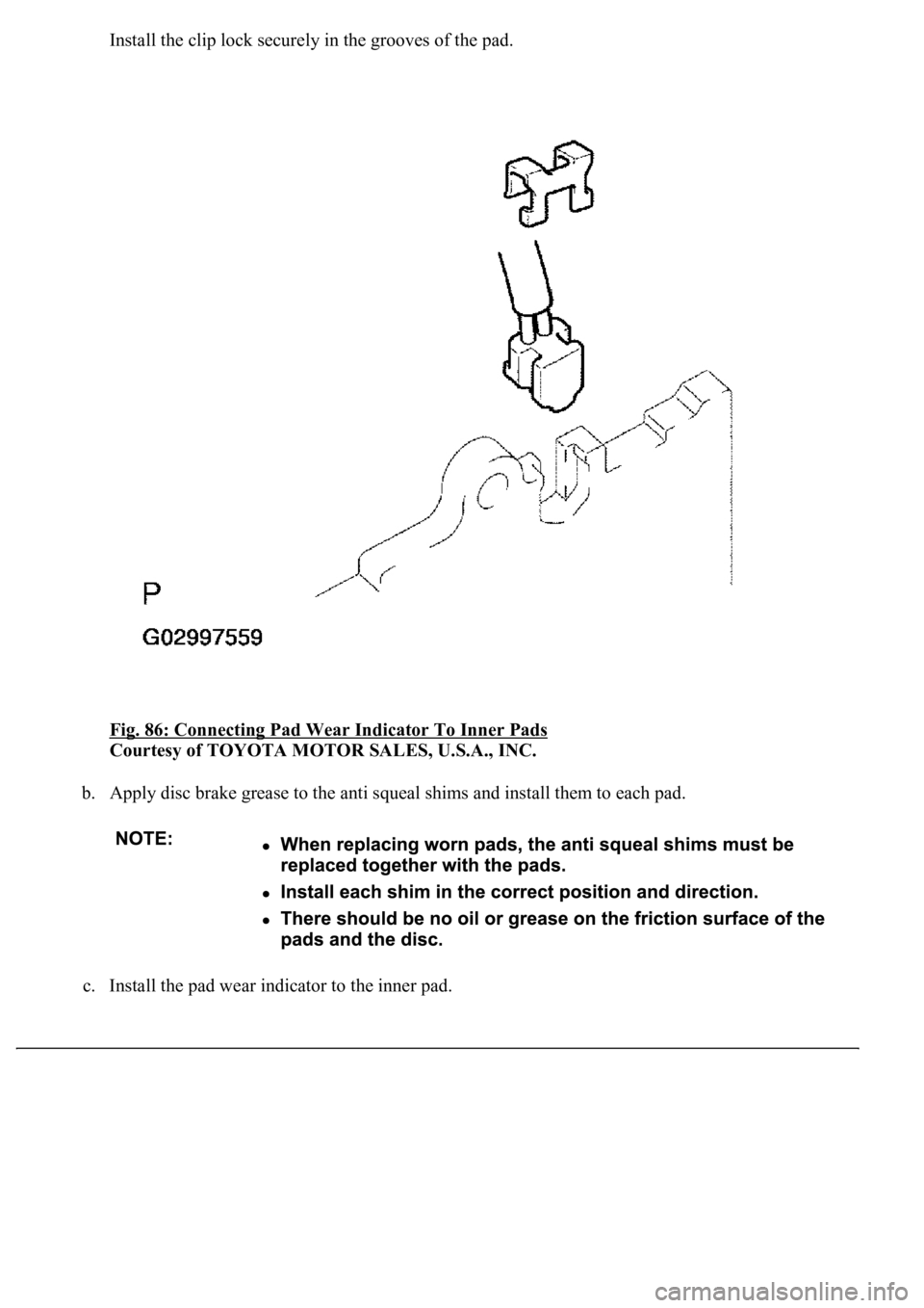
Connect the pad wear indicator to the inner pads, and install a new clip.
HINT:
Page 1054 of 4500
Install the clip lock securely in the grooves of the pad.
Fig. 86: Connecting Pad Wear Indicator To Inner Pads
Courtesy of TOYOTA MOTOR SALES, U.S.A., INC.
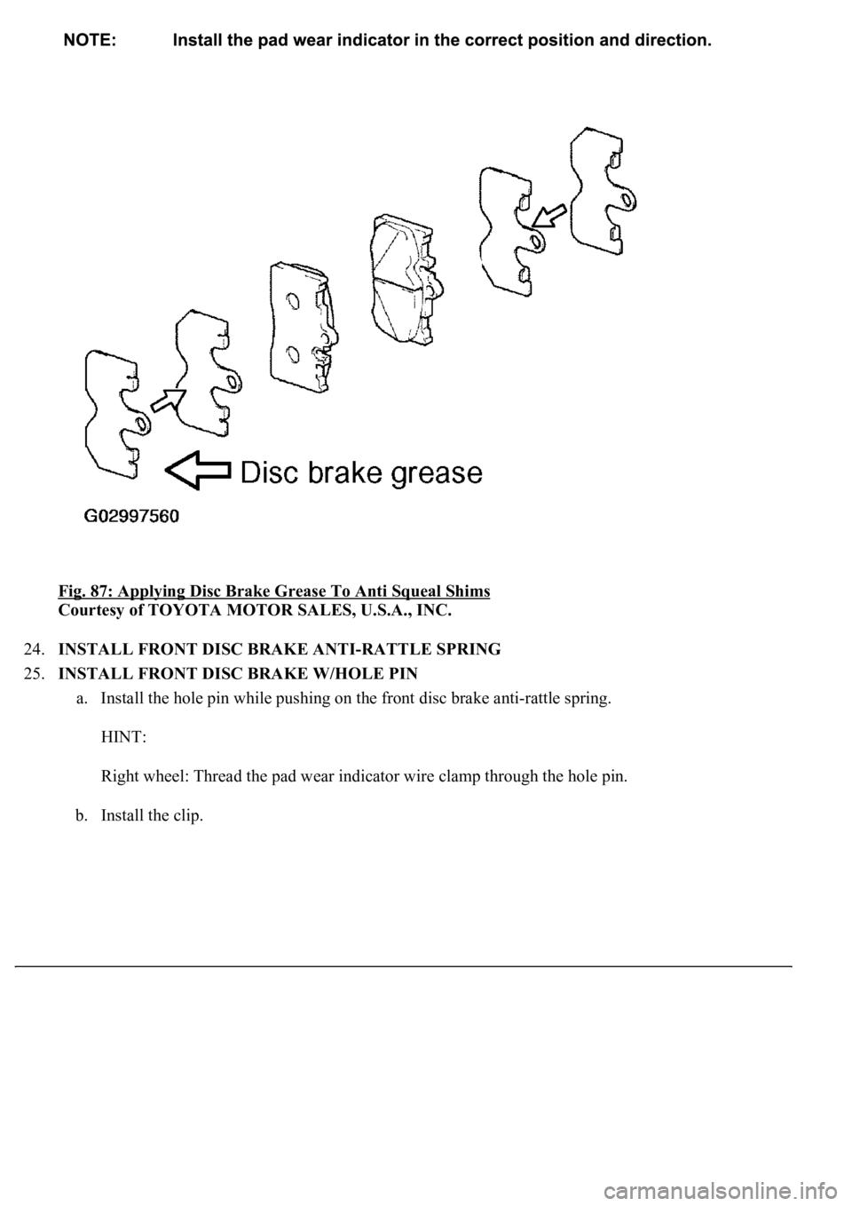
b. Apply disc brake grease to the anti squeal shims and install them to each pad.
c. Install the pad wear indicator to the inner pad.
Page 1055 of 4500
Fig. 87: Applying Disc Brake Grease To Anti Squeal Shims
Courtesy of TOYOTA MOTOR SALES, U.S.A., INC.
24.INSTALL FRONT DISC BRAKE ANTI-RATTLE SPRING
25.INSTALL FRONT DISC BRAKE W/HOLE PIN
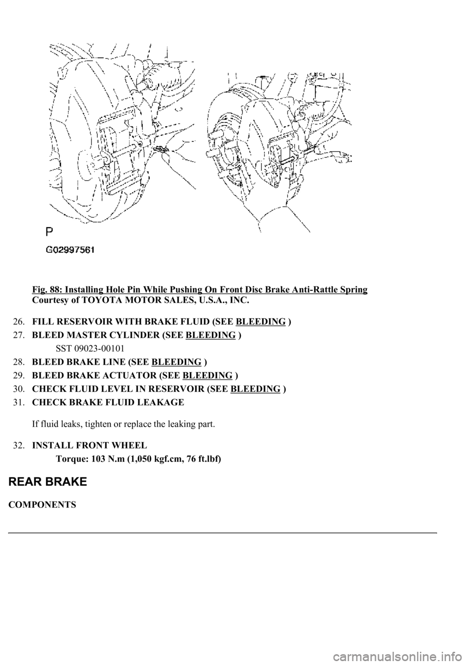
a. Install the hole pin while pushing on the front disc brake anti-rattle spring.
HINT:
Right wheel: Thread the pad wear indicator wire clamp through the hole pin.
b. Install the clip.
Page 1056 of 4500
Fig. 88: Installing Hole Pin While Pushing On Front Disc Brake Anti-Rattle Spring
Courtesy of TOYOTA MOTOR SALES, U.S.A., INC.
26.FILL RESERVOIR WITH BRAKE FLUID (SEE BLEEDING
)
27.BLEED MASTER CYLINDER (SEE BLEEDING
)
SST 09023-00101
28.BLEED BRAKE LINE (SEE BLEEDING
)
29.BLEED BRAKE ACTUATOR (SEE BLEEDING
)
30.CHECK FLUID LEVEL IN RESERVOIR (SEE BLEEDING
)
31.CHECK BRAKE FLUID LEAKAGE
If fluid leaks, tighten or replace the leaking part.
32.INSTALL FRONT WHEEL
Torque: 103 N.m (1,050 kgf.cm, 76 ft.lbf)
COMPONENTS
Page 1057 of 4500
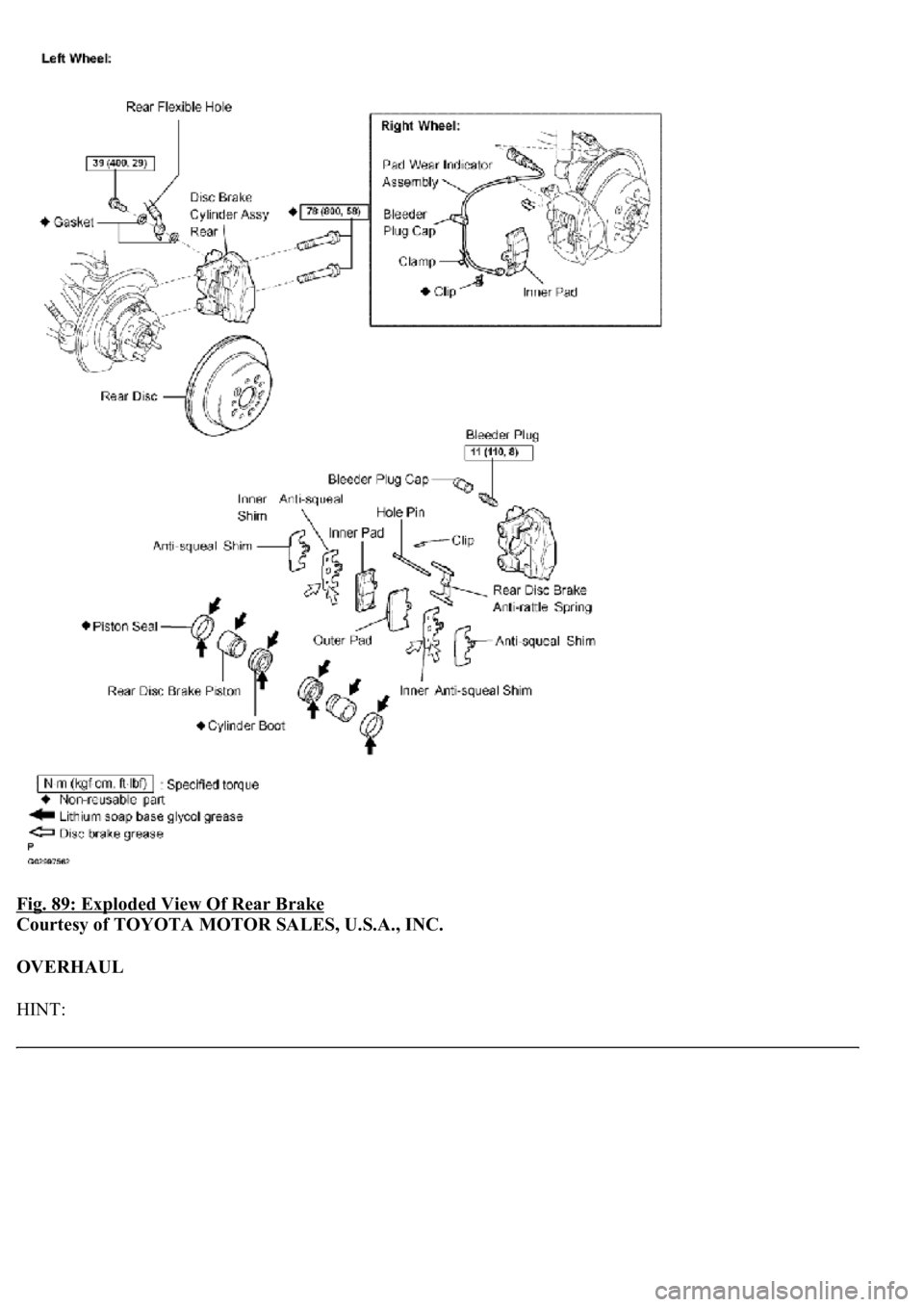
Fig. 89: Exploded View Of Rear Brake
Courtesy of TOYOTA MOTOR SALES, U.S.A., INC.
OVERHAUL
HINT:
Page 1058 of 4500
Overhaul the RH side by using the same procedures as for the LH side.
1.REMOVE REAR WHEEL
2.DRAIN BRAKE FLUID
a. Draw out fluid with syringe.
3.REMOVE REAR DISC BRAKE W/HOLE PIN
a. Remove the clip.
b. Remove the rear disc brake w/hole pin while pushing on the rear disc brake anti-rattle spring.
4.REMOVE REAR DISC BRAKE ANTI-RATTLE SPRING
5.REMOVE DISC BRAKE PAD KIT REAR (PAD ONLY)
a. Remove the 2 pads and the 2 anti-squeal shims from each pad.
Page 1059 of 4500
Fig. 90: Removing Rear Disc Brake W/Hole Pin While Pushing On Rear Disc Brake Anti-
Rattle Spring
Courtesy of TOYOTA MOTOR SALES, U.S.A., INC.
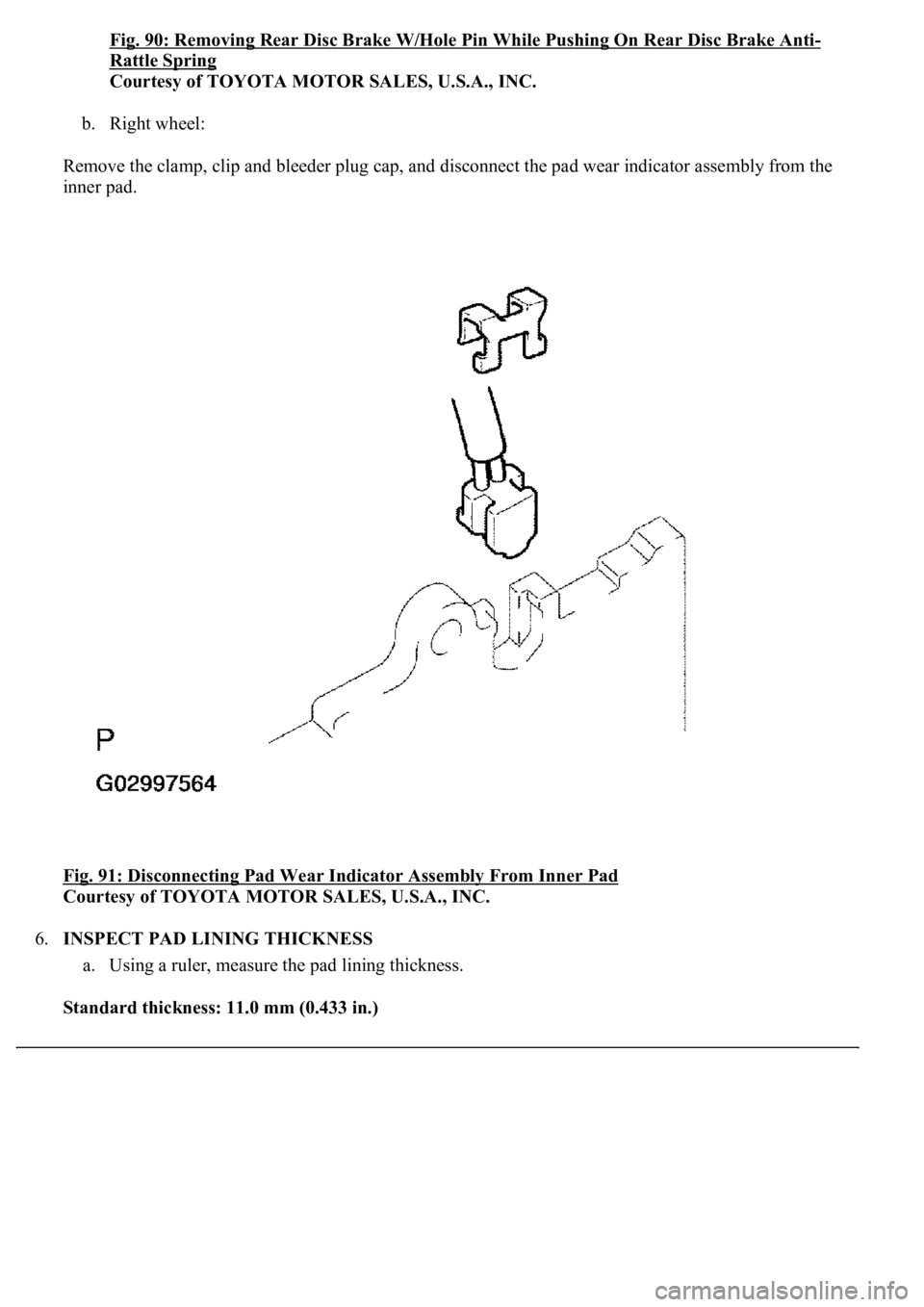
b. Right wheel:
Remove the clamp, clip and bleeder plug cap, and disconnect the pad wear indicator assembly from the
inner pad.
<0029004c004a00110003001c0014001d00030027004c00560046005200510051004800460057004c0051004a00030033004400470003003a0048004400550003002c00510047004c004600440057005200550003002400560056004800500045004f005c00
0300290055005200500003002c005100510048005500030033[ad
Courtesy of TOYOTA MOTOR SALES, U.S.A., INC.
6.INSPECT PAD LINING THICKNESS
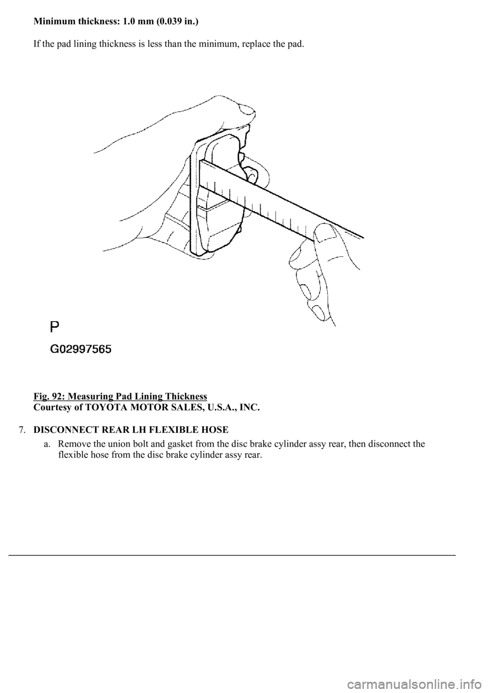
a. Using a ruler, measure the pad lining thickness.
Standard thickness: 11.0 mm (0.433 in.)
Page 1060 of 4500
Minimum thickness: 1.0 mm (0.039 in.)
If the pad lining thickness is less than the minimum, replace the pad.
Fig. 92: Measuring Pad Lining Thickness
Courtesy of TOYOTA MOTOR SALES, U.S.A., INC.
7.DISCONNECT REAR LH FLEXIBLE HOSE
a. Remove the union bolt and gasket from the disc brake cylinder assy rear, then disconnect the
flexible hose from the disc brake c
ylinder assy rear.
Trending: Rear control Arm, air condition, phone, lumbar support, snow chains, actuator damper, tires
