LEXUS LS430 2003 Factory Repair Manual
Manufacturer: LEXUS, Model Year: 2003,
Model line: LS430,
Model: LEXUS LS430 2003
Pages: 4500, PDF Size: 87.45 MB
LEXUS LS430 2003 Factory Repair Manual
LS430 2003
LEXUS
LEXUS
https://www.carmanualsonline.info/img/36/57050/w960_57050-0.png
LEXUS LS430 2003 Factory Repair Manual
Trending: boot, washer fluid, electronic modulated, buttons, B2419 bean, headrest, c1751
Page 1081 of 4500
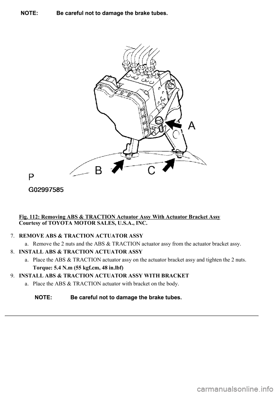
Fig. 112: Removing ABS & TRACTION Actuator Assy With Actuator Bracket Assy
Courtesy of TOYOTA MOTOR SALES, U.S.A., INC.
7.REMOVE ABS & TRACTION ACTUATOR ASSY
a. Remove the 2 nuts and the ABS & TRACTION actuator assy from the actuator bracket assy.
8.INSTALL ABS & TRACTION ACTUATOR ASSY
a. Place the ABS & TRACTION actuator assy on the actuator bracket assy and tighten the 2 nuts.
Torque: 5.4 N.m (55 kgf.cm, 48 in.lbf)
9.INSTALL ABS & TRACTION ACTUATOR ASSY WITH BRACKET
a. Place the ABS & TRACTION actuator with bracket on the body.
Page 1082 of 4500
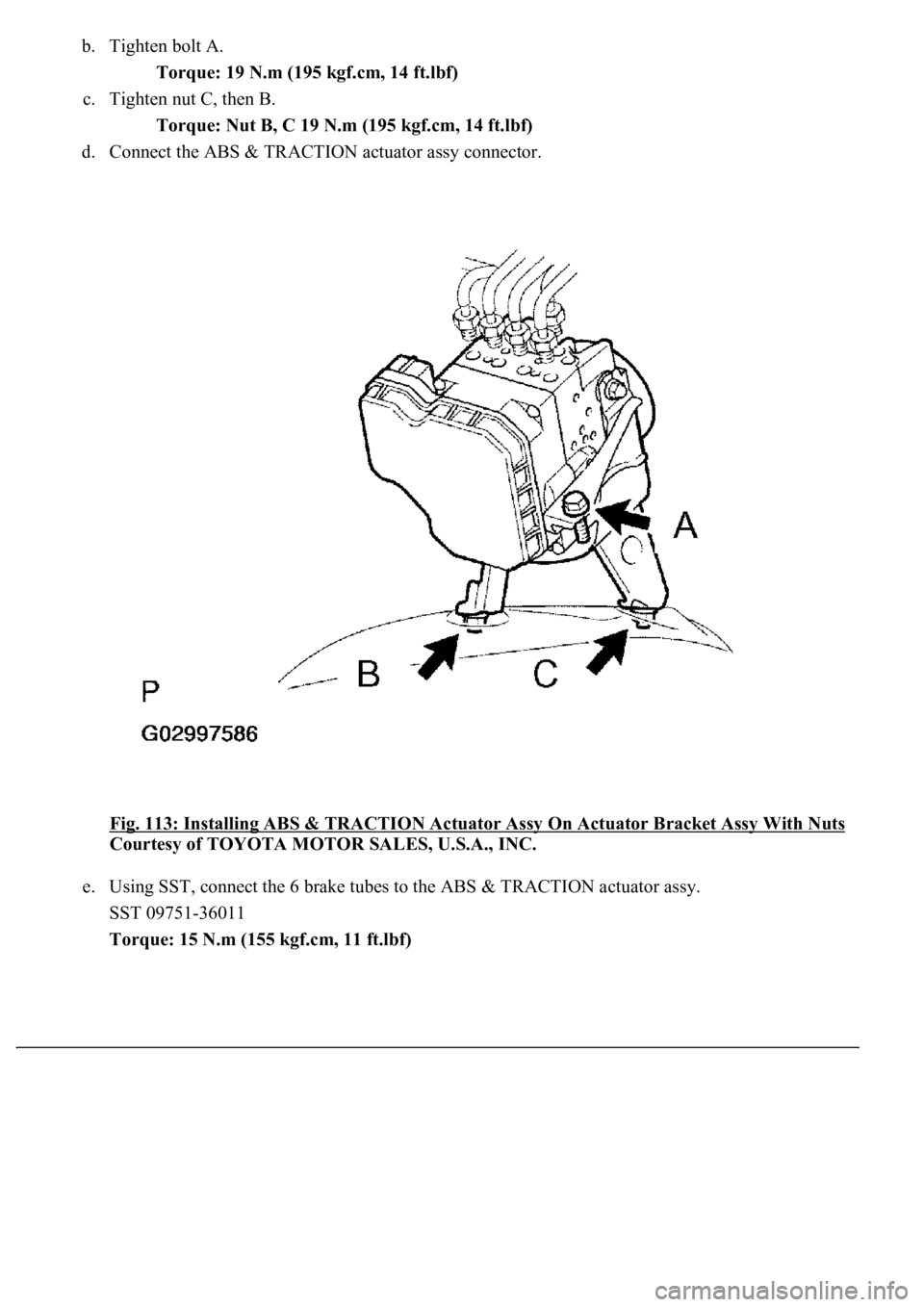
b. Tighten bolt A.
Torque: 19 N.m (195 kgf.cm, 14 ft.lbf)
c. Tighten nut C, then B.
Torque: Nut B, C 19 N.m (195 kgf.cm, 14 ft.lbf)
d. Connect the ABS & TRACTION actuator assy connector.
Fig. 113: Installing ABS & TRACTION Actuator Assy On Actuator Bracket Assy With Nuts
Courtesy of TOYOTA MOTOR SALES, U.S.A., INC.
e. Using SST, connect the 6 brake tubes to the ABS & TRACTION actuator assy.
SST 09751-36011
Torque: 15 N.m (155 kgf.cm, 11 ft.lbf)
Page 1083 of 4500
Fig. 114: Connecting Brake Tubes To ABS & TRACTION Actuator Assy
Courtesy of TOYOTA MOTOR SALES, U.S.A., INC.
10.FILL RESERVOIR WITH BRAKE FLUID (SEE BLEEDING
)
11.BLEED MASTER CYLINDER (SEE BLEEDING
)
12.BLEED BRAKE LINE (SEE BLEEDING
)
13.CHECK FLUID LEVEL IN RESERVOIR (SEE BLEEDING
)
a. Check the fluid level and add fluid, if necessary.
Fluid: SAE J1703 or JMVSS No. 116 DOT 3
14.CHECK BRAKE FLUID LEAKAGE
If fluid leaks, tighten or replace the leaking part.
15.CHECK ABS & TRACTION ACTUATOR WITH HAND HELD TESTER (SEE DIAGNOSIS
SYSTEM )
16.CLEAR DTC (SEE DIAGNOSIS SYSTEM
)
17.INSTALL FRONT FENDER LINER
a. Install the front fender liner LH, front fender splash shield and front fender outside mouldin
g.
Page 1084 of 4500
18.INSTALL FRONT WHEEL
19.CONNECT ENGINE ROOM NO.3 R/B
a. Install the engine room No.3 R/B and bolt.
20.INSTALL ENGINE ROOM SIDE COVER
21.PERFORM YAWRATE SENSOR ZERO POINT CALIBRATION AND TEST MODE
COMPONENTS
Page 1085 of 4500
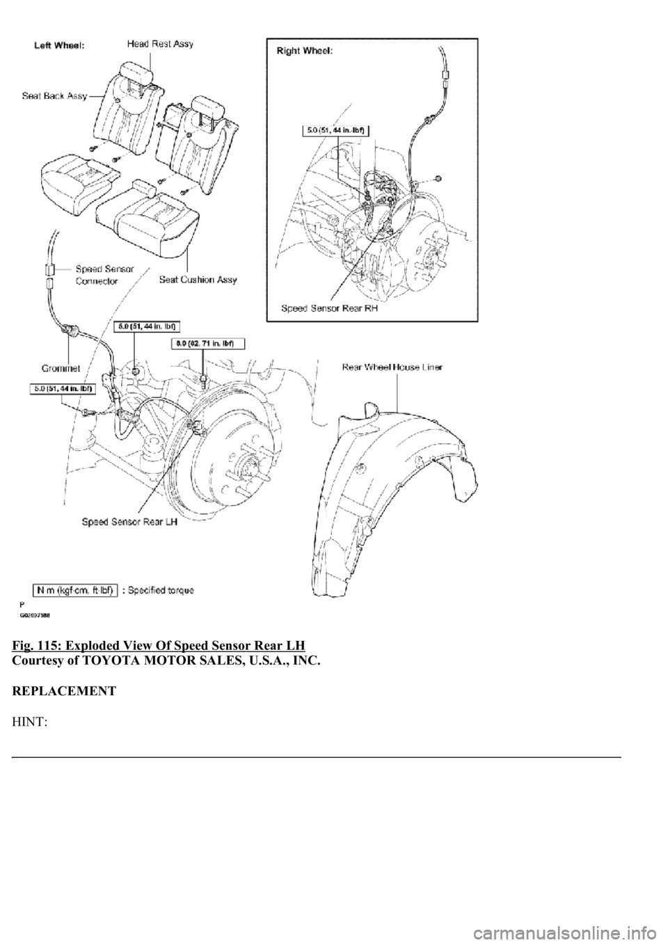
Fig. 115: Exploded View Of Speed Sensor Rear LH
Courtesy of TOYOTA MOTOR SALES, U.S.A., INC.
REPLACEMENT
HINT:
Page 1086 of 4500
Replace the RH side by using the same procedures as for the LH side.
The procedures listed below are for the LH side.
1.REMOVE REAR SEAT CUSHION ASSY (SEE OVERHAUL
- FIXED TYPE or OVERHAUL -
POWER ADJUSTER TYPE
)
2.REMOVE REAR SEAT HEAD REST ASSY (SEE OVERHAUL
- FIXED TYPE or OVERHAUL -
POWER ADJUSTER TYPE )
3.REMOVE REAR SEATBACK ASSY (SEE OVERHAUL
- FIXED TYPE or OVERHAUL -
POWER ADJUSTER TYPE
)
4.REMOVE REAR WHEEL
5.REMOVE REAR WHEEL HOUSE LH LINER
6.REMOVE SPEED SENSOR REAR LH
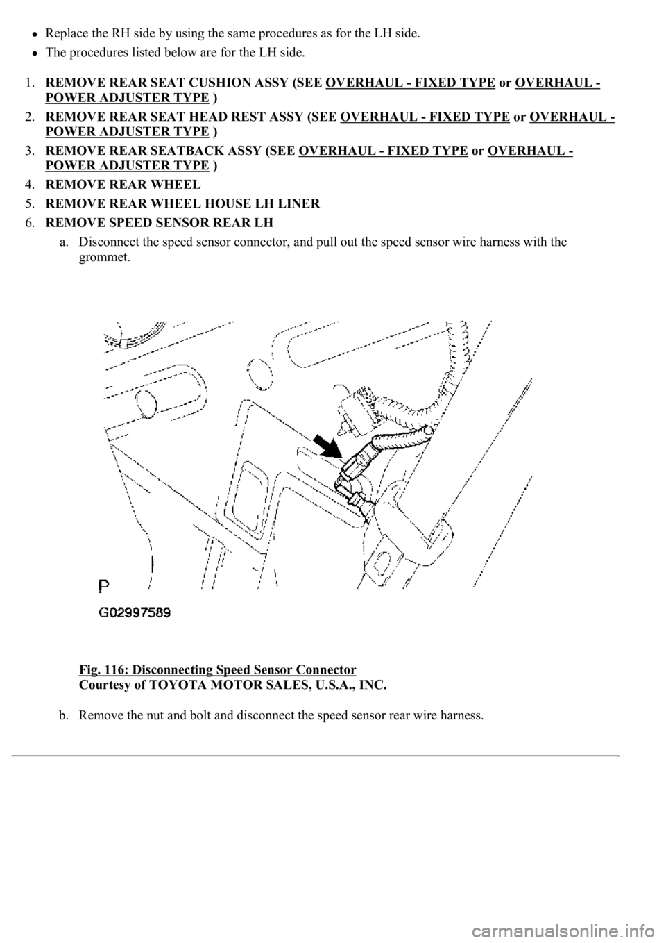
a. Disconnect the speed sensor connector, and pull out the speed sensor wire harness with the
grommet.
Fig. 116: Disconnecting Speed Sensor Connector
Courtesy of TOYOTA MOTOR SALES, U.S.A., INC.
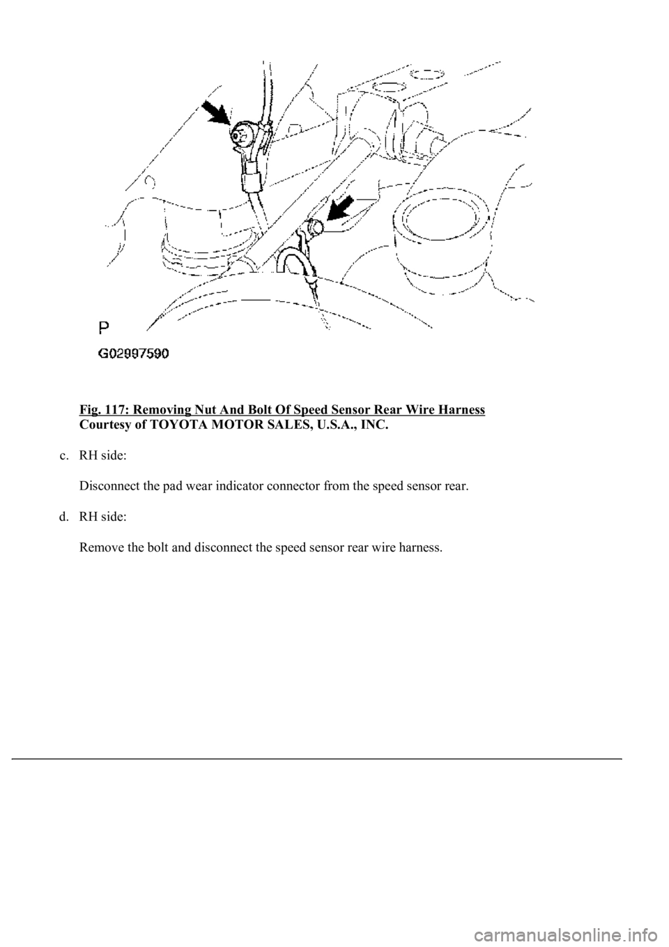
b. Remove the nut and bolt and disconnect the speed sensor rear wire harness.
Page 1087 of 4500
Fig. 117: Removing Nut And Bolt Of Speed Sensor Rear Wire Harness
Courtesy of TOYOTA MOTOR SALES, U.S.A., INC.
c. RH side:
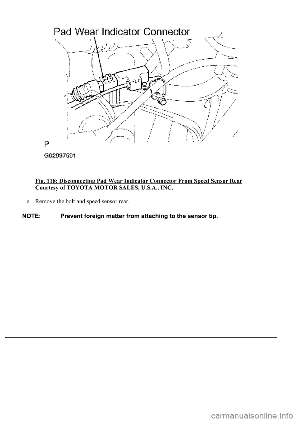
Disconnect the pad wear indicator connector from the speed sensor rear.
d. RH side:
Remove the bolt and disconnect the speed sensor rear wire harness.
Page 1088 of 4500
Fig. 118: Disconnecting Pad Wear Indicator Connector From Speed Sensor Rear
Courtesy of TOYOTA MOTOR SALES, U.S.A., INC.
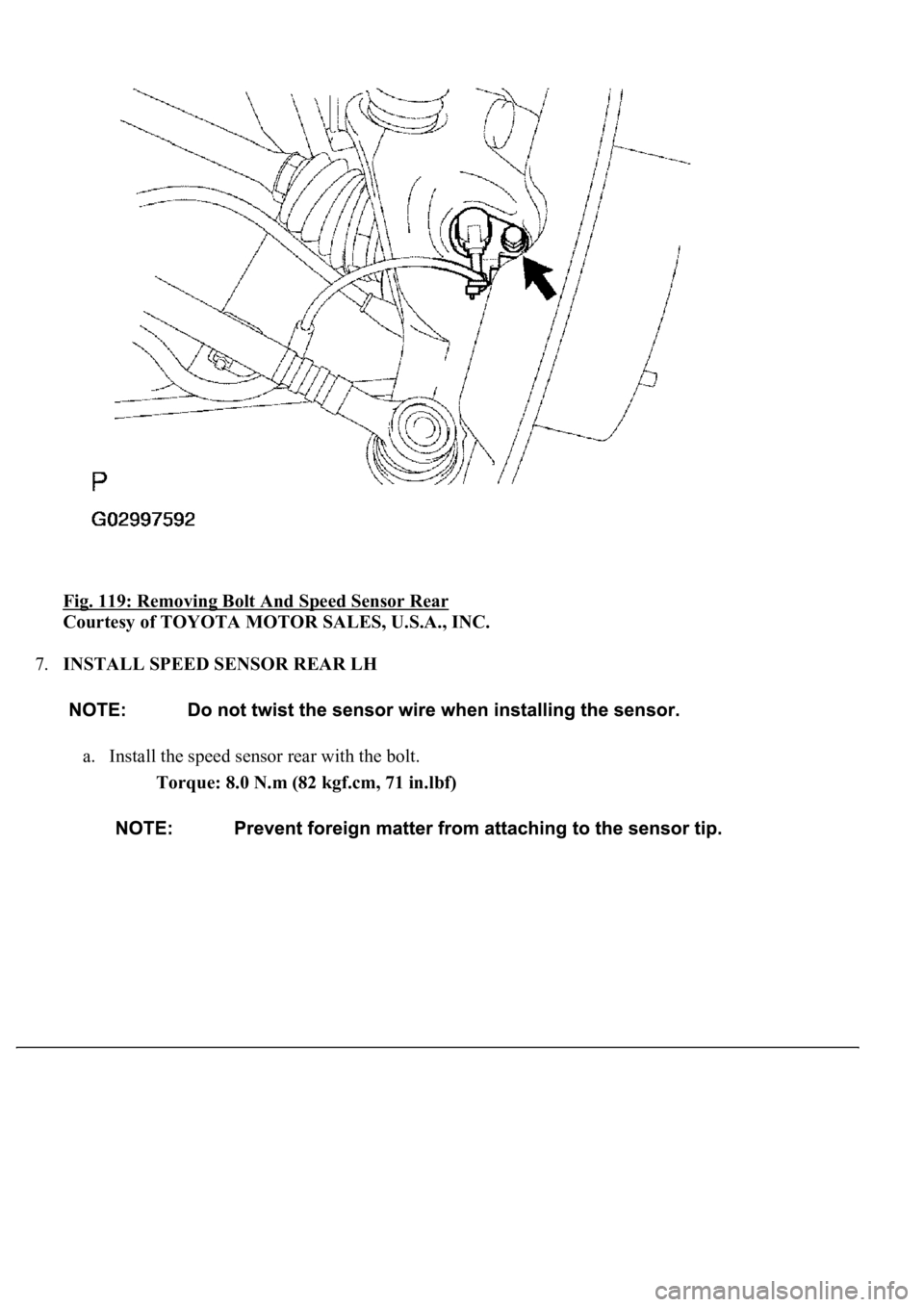
e. Remove the bolt and speed sensor rear.
Page 1089 of 4500
Fig. 119: Removing Bolt And Speed Sensor Rear
Courtesy of TOYOTA MOTOR SALES, U.S.A., INC.
7.INSTALL SPEED SENSOR REAR LH
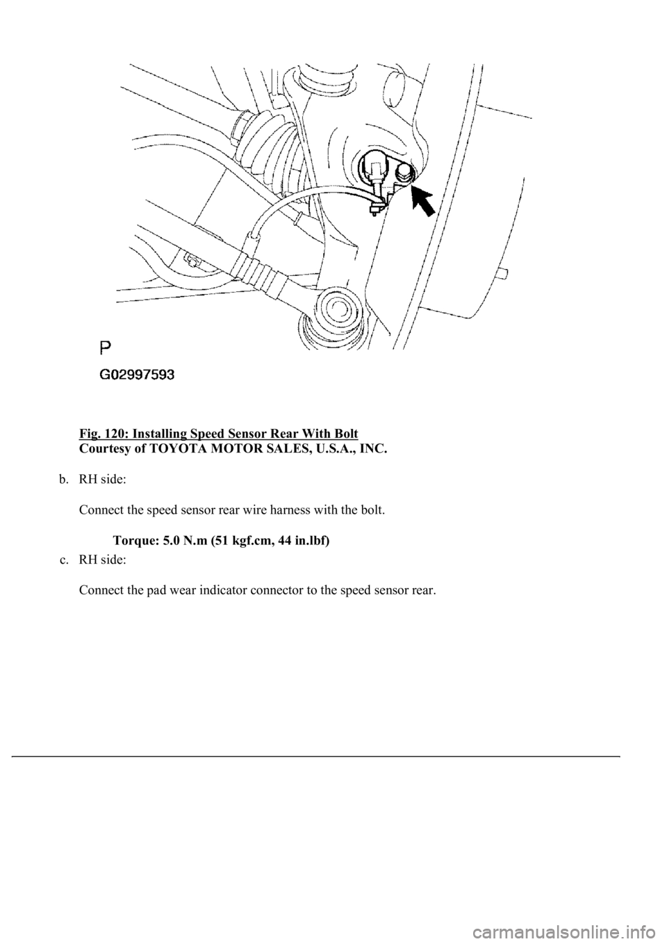
a. Install the speed sensor rear with the bolt.
Torque: 8.0 N.m (82 kgf.cm, 71 in.lbf)
Page 1090 of 4500
Fig. 120: Installing Speed Sensor Rear With Bolt
Courtesy of TOYOTA MOTOR SALES, U.S.A., INC.
b. RH side:
Connect the speed sensor rear wire harness with the bolt.
Torque: 5.0 N.m (51 kgf.cm, 44 in.lbf)
c. RH side:
Connect the pad wear indicator connector to the speed sensor rear.
Trending: Combination, wiring, wheel alignment, Absorber suspension, engine coolant, warning, Suspension control
