LEXUS LS430 2003 Factory Repair Manual
Manufacturer: LEXUS, Model Year: 2003,
Model line: LS430,
Model: LEXUS LS430 2003
Pages: 4500, PDF Size: 87.45 MB
LEXUS LS430 2003 Factory Repair Manual
LS430 2003
LEXUS
LEXUS
https://www.carmanualsonline.info/img/36/57050/w960_57050-0.png
LEXUS LS430 2003 Factory Repair Manual
Trending: Combination, coolant temperature, window, lumbar support, intake manifold inlet, radiator, turn signal
Page 1191 of 4500
1.STEERING SYSTEM HANDLING PRECAUTIONS
a. Care must be taken when replacing parts. Incorrect replacement could affect the performance of the
steering system and result in hazardous driving.
2.SRS AIRBAG SYSTEM HANDLING PRECAUTIONS
a. The LEXUS LS430 is equipped with an SRS (Supplemental Restraint System) such as the driver's
airbag and front passenger airbag. Failure to carry out service operations in correct sequence could
cause unexpected SRS deployment during servicing and may lead to a serious accident. Before
servicing (including removal or installation of parts, inspection or replacement), be sure to read the
precautionary notice for the supplemental restraint system (see PRECAUTION
).
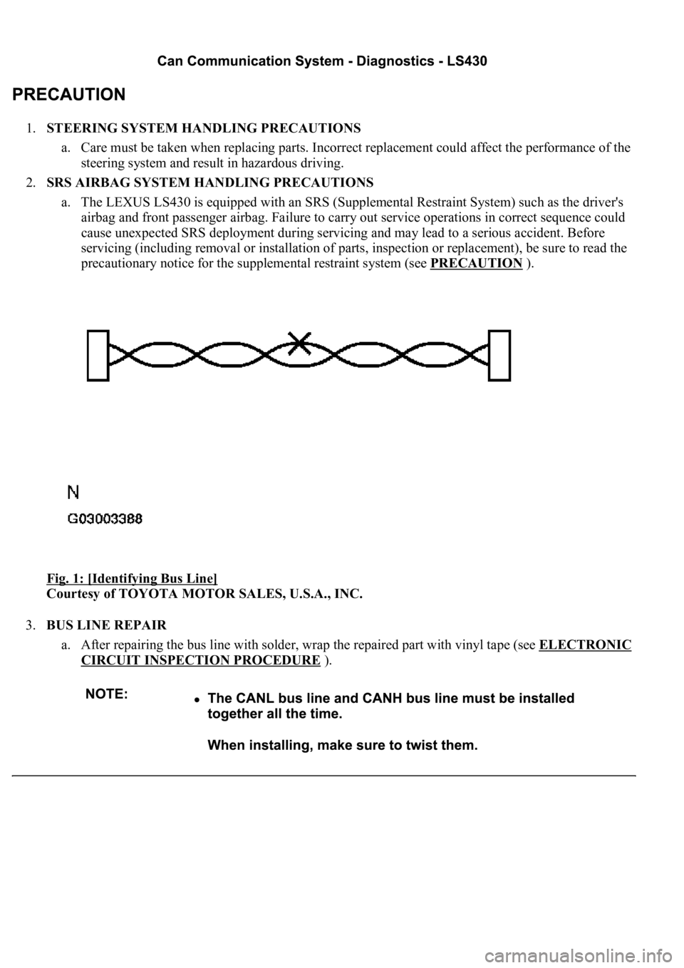
Fig. 1: [Identifying Bus Line]
Courtesy of TOYOTA MOTOR SALES, U.S.A., INC.
3.BUS LINE REPAIR
a. After repairing the bus line with solder, wrap the repaired part with vinyl tape (see ELECTRONIC
CIRCUIT INSPECTION PROCEDURE ).
Page 1192 of 4500
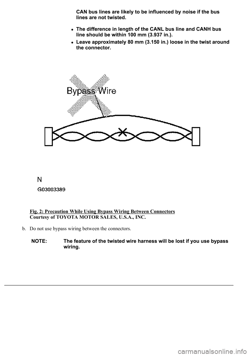
Fig. 2: Precaution While Using Bypass Wiring Between Connectors
Courtesy of TOYOTA MOTOR SALES, U.S.A., INC.
b. Do not use bypass wiring between the connectors.
Page 1193 of 4500
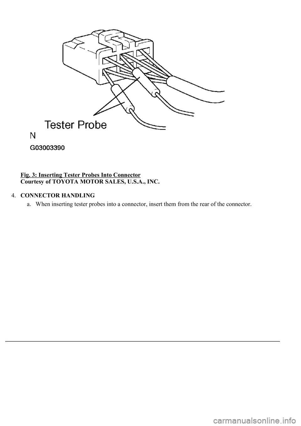
Fig. 3: Inserting Tester Probes Into Connector
Courtesy of TOYOTA MOTOR SALES, U.S.A., INC.
4.CONNECTOR HANDLING
a. When insertin
g tester probes into a connector, insert them from the rear of the connector.
Page 1194 of 4500
Fig. 4: Checking Continuity Between Connectors From Rear Side
Courtesy of TOYOTA MOTOR SALES, U.S.A., INC.
b. Use a repair wire to check the connector if it is impossible to check continuity from the rear of the
connector.
5.PRECAUTION FOR DISCONNECTING THE BATTERY CABLE
SYSTEM NAME AND PAGE REFERENCE
System NameSee Procedure
Front Power Seat Control SystemINITIALIZATION
Page 1195 of 4500
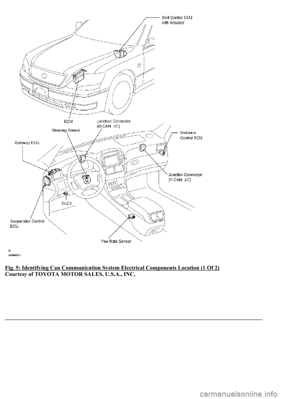
Fig. 5: Identifying Can Communication System Electrical Components Location (1 Of 2)
Courtesy of TOYOTA MOTOR SALES, U.S.A., INC.
Page 1196 of 4500
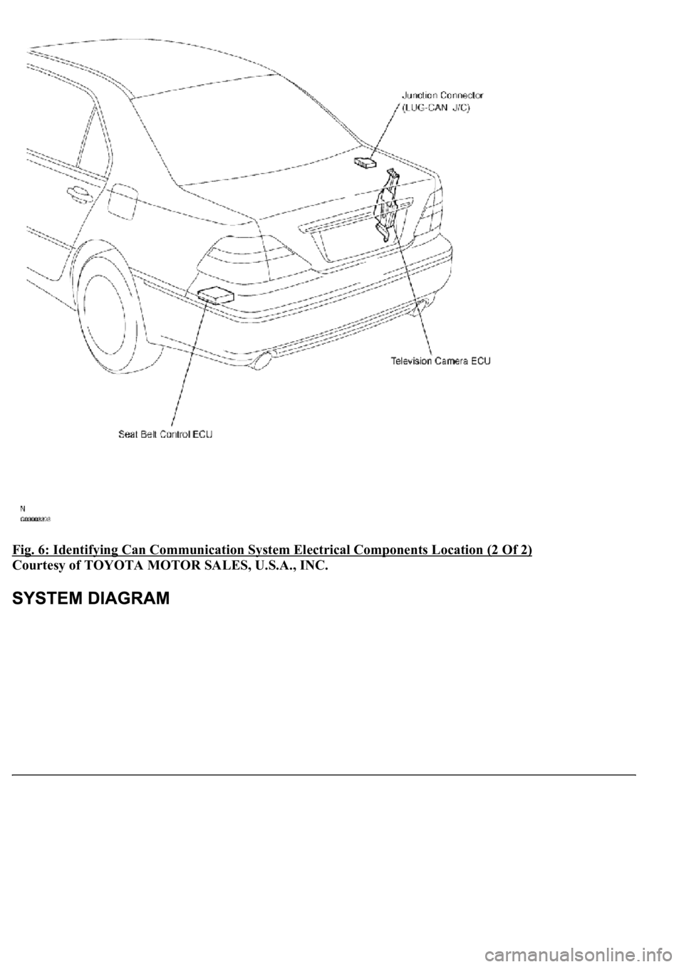
Fig. 6: Identifying Can Communication System Electrical Components Location (2 Of 2)
Courtesy of TOYOTA MOTOR SALES, U.S.A., INC.
Page 1197 of 4500
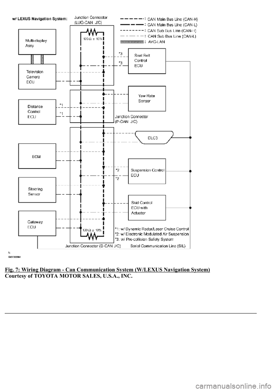
Fig. 7: Wiring Diagram - Can Communication System (W/LEXUS Navigation System)
Courtesy of TOYOTA MOTOR SALES, U.S.A., INC.
Page 1198 of 4500
Fig. 8: Wiring Diagram - Can Communication System (W/O LEXUS Navigation System)
Courtesy of TOYOTA MOTOR SALES, U.S.A., INC.
HINT:
The position of the terminus circuit differs in vehicles with and without the LEXUS navigation system.
The skid control ECU with actuator detects and stores steering sensor and yaw rate sensor DTCs and
performs DTC communication by receiving information from the steering sensor and yaw rate sensor.
The ECM detects and stores distance control ECU DTCs, and performs DTC communication by
receiving information from the distance control ECU.
The ECM uses the CAN communication system to perform DTC communication instead of the
Page 1199 of 4500

conventional communication line (SIL).
1.BRIEF DESCRIPTION
a. The CAN (Controller Area Network) is a serial data communication system for real time
application. It is a multiplex communication system equipped for a vehicle and has a high
communication speed (500 kbps) and the function to detect malfunctions.
b. By pairing the CANH and CANL bus lines, the CAN performs communication based on
differential voltage.
c. Many ECUs (sensors) installed on the vehicle operate by sharing information and communicating
with each other.
d. The CAN has two resistors of 120 ohms which are necessary to communicate with the main bus
line.
2.DEFINITION OF TERMS
a. Main bus line
1. The main bus line is the wire harness between the two terminus circuits on the bus
(communication line). This is the main bus in the CAN communication system.
b. Sub bus line
1. The sub bus line is the wire harness which diverges from the main bus line to the ECU or
sensor.
c. Terminus circuit
1. The terminus circuit is a circuit which is placed to convert communication current of the
CAN communication into bus voltage. It consists of a resistor and condenser. Two terminus
circuits are necessary on a bus.
d. CAN J/C
1. The CAN J/C is a junction designed for CAN communication, which stores a terminus
circuit.
3.ECUs OR SENSORS WHICH COMMUNICATE THROUGH CAN COMMUNICATION
SYSTEM
a. Skid Control ECU with Actuator
b. Yaw Rate Sensor
c. Steering Sensor
d. Television Camera ECU
e. Seat Belt Control ECU
f. Distance Control ECU
g. Suspension Control ECU
h. ECM
i. Gateway ECU
4.DIAGNOSTIC CODE FOR CAN COMMUNICATION SYSTEM
a. DTCs for the CAN communication system are as follows:
Page 1200 of 4500
U0073, U0100, U0101, U0122, U0123, U0124, U0126, U0132, U0145, U1101
5.REMARK FOR TROUBLESHOOTING
a. Trouble in the CAN bus (communication line) can be checked from the DLC3 (except when there
is a wire break other than in the sub bus line of the DLC3).
b. DTCs regarding the CAN communication system can be checked using the hand-held tester via the
CAN VIM.
c. The CAN communication system cannot detect trouble in the sub bus line of the DLC3 even
though the DLC3 is also connected to the CAN communication system.
6.HOW TO DISTINGUISH THE CAN J/C CONNECTOR
a. In the CAN communication system, the shape of all connectors connected to the CAN J/C is the
same. The connectors connected to the CAN J/C can be distinguished by the colors of the bus lines
and the connecting side of the connector.
HINT:
See TERMINALS OF ECU
for bus line color or the type of connecting surface.
1.CHECK AND CLEAR DTCs
2.CHECK FOR INSTALLED SYSTEMS (ECUS & SENSORS) THAT ADOPT CAN
COMMUNICATION)
a. Check which of the following is adopted: LEXUS Navigation System, dynamic radar/laser cruise
control, and electronic modulated air suspension (see DIAGNOSIS SYSTEM
).
3.(SEE CHECK CAN BUS LINE
)
4.CHECK HAND-HELD TESTER VIA CAN VIM
a. Select "BUS CHECK" (see DIAGNOSIS SYSTEM
).
Standard: All ECUs and sensors connected to the CAN communication system are displayed.
Trending: display, fuel system, lane assist, ground clearance, illumination, inter lock cable, Rear control Arm
