LEXUS LS430 2003 Factory Repair Manual
Manufacturer: LEXUS, Model Year: 2003,
Model line: LS430,
Model: LEXUS LS430 2003
Pages: 4500, PDF Size: 87.45 MB
LEXUS LS430 2003 Factory Repair Manual
LS430 2003
LEXUS
LEXUS
https://www.carmanualsonline.info/img/36/57050/w960_57050-0.png
LEXUS LS430 2003 Factory Repair Manual
Trending: fuel system, ECO mode, lane assist, air conditioning, torque, Spd, set clock
Page 1221 of 4500
Fig. 24: Identifying Suspension Control ECU Connector Terminals
Courtesy of TOYOTA MOTOR SALES, U.S.A., INC.
Page 1222 of 4500
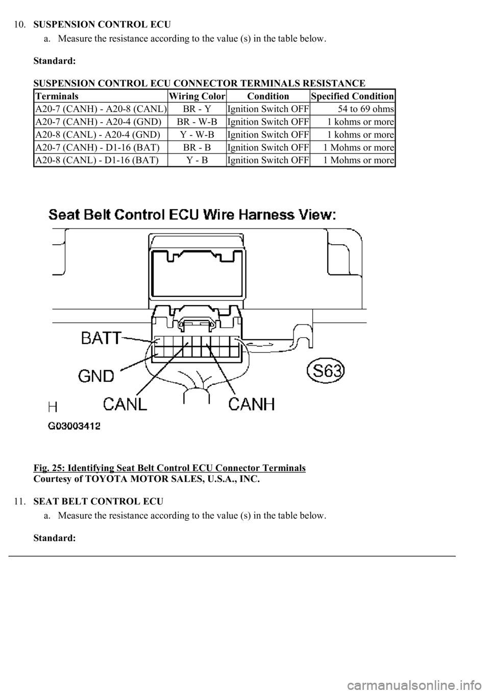
10.SUSPENSION CONTROL ECU
a. Measure the resistance according to the value (s) in the table below.
Standard:
SUSPENSION CONTROL ECU CONNECTOR TERMINALS RESISTANCE
Fig. 25: Identifying Seat Belt Control ECU Connector Terminals
Courtesy of TOYOTA MOTOR SALES, U.S.A., INC.
11.SEAT BELT CONTROL ECU
a. Measure the resistance according to the value (s) in the table below.
Standard:
TerminalsWiring ColorConditionSpecified Condition
A20-7 (CANH) - A20-8 (CANL)BR - YIgnition Switch OFF54 to 69 ohms
A20-7 (CANH) - A20-4 (GND)BR - W-BIgnition Switch OFF1 kohms or more
A20-8 (CANL) - A20-4 (GND)Y - W-BIgnition Switch OFF1 kohms or more
A20-7 (CANH) - D1-16 (BAT)BR - BIgnition Switch OFF1 Mohms or more
A20-8 (CANL) - D1-16 (BAT)Y - BIgnition Switch OFF1 Mohms or more
Page 1223 of 4500
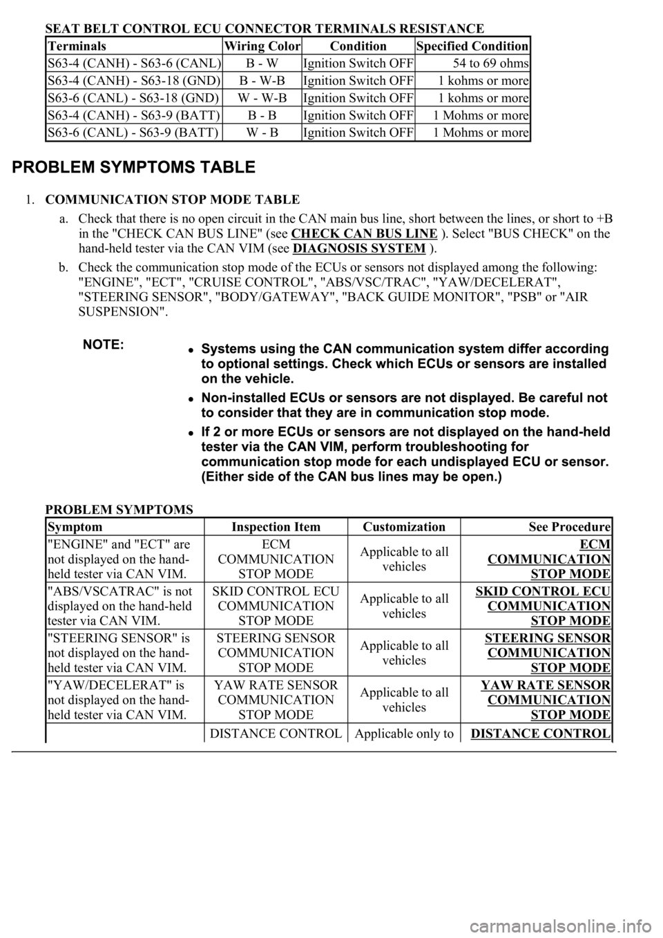
SEAT BELT CONTROL ECU CONNECTOR TERMINALS RESISTANCE
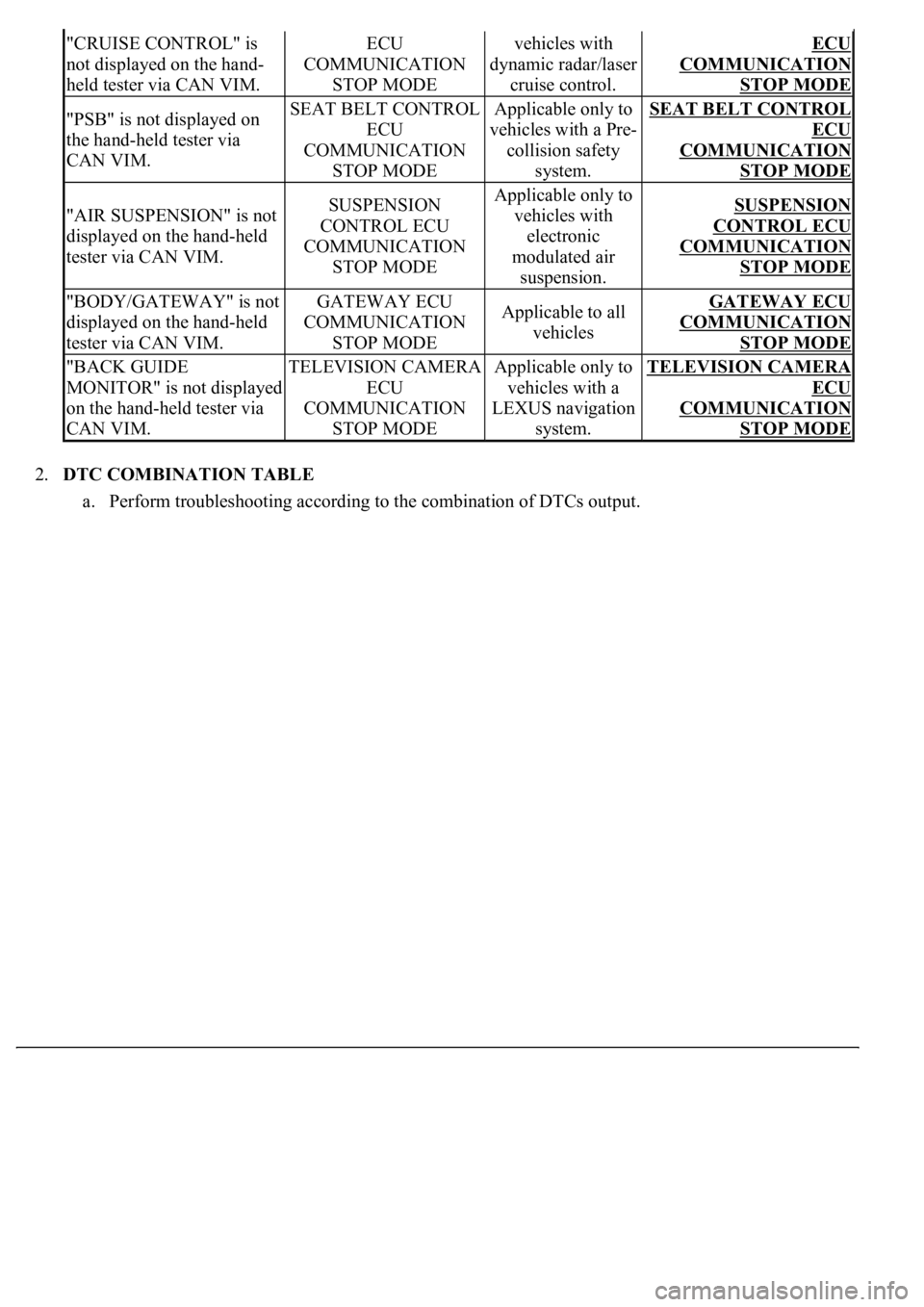
1.COMMUNICATION STOP MODE TABLE
a. Check that there is no open circuit in the CAN main bus line, short between the lines, or short to +B
in the "CHECK CAN BUS LINE" (see CHECK CAN BUS LINE
). Select "BUS CHECK" on the
hand-held tester via the CAN VIM (see DIAGNOSIS SYSTEM
).
b. Check the communication stop mode of the ECUs or sensors not displayed among the following:
"ENGINE", "ECT", "CRUISE CONTROL", "ABS/VSC/TRAC", "YAW/DECELERAT",
"STEERING SENSOR", "BODY/GATEWAY", "BACK GUIDE MONITOR", "PSB" or "AIR
SUSPENSION".
PROBLEM SYMPTOMS
TerminalsWiring ColorConditionSpecified Condition
S63-4 (CANH) - S63-6 (CANL)B - WIgnition Switch OFF54 to 69 ohms
S63-4 (CANH) - S63-18 (GND)B - W-BIgnition Switch OFF1 kohms or more
S63-6 (CANL) - S63-18 (GND)W - W-BIgnition Switch OFF1 kohms or more
S63-4 (CANH) - S63-9 (BATT)B - BIgnition Switch OFF1 Mohms or more
S63-6 (CANL) - S63-9 (BATT)W - BIgnition Switch OFF1 Mohms or more
SymptomInspection ItemCustomizationSee Procedure
"ENGINE" and "ECT" are
not displayed on the hand-
held tester via CAN VIM.ECM
COMMUNICATION
STOP MODEApplicable to all
vehiclesECM
COMMUNICATION
STOP MODE
"ABS/VSCATRAC" is not
displayed on the hand-held
tester via CAN VIM.SKID CONTROL ECU
COMMUNICATION
STOP MODEApplicable to all
vehiclesSKID CONTROL ECU
COMMUNICATION
STOP MODE
"STEERING SENSOR" is
not displayed on the hand-
held tester via CAN VIM.STEERING SENSOR
COMMUNICATION
STOP MODEApplicable to all
vehiclesSTEERING SENSOR
COMMUNICATION
STOP MODE
"YAW/DECELERAT" is
not displayed on the hand-
held tester via CAN VIM.YAW RATE SENSOR
COMMUNICATION
STOP MODEApplicable to all
vehiclesYAW RATE SENSOR
COMMUNICATION
STOP MODE
DISTANCE CONTROL Applicable only to DISTANCE CONTROL
Page 1224 of 4500
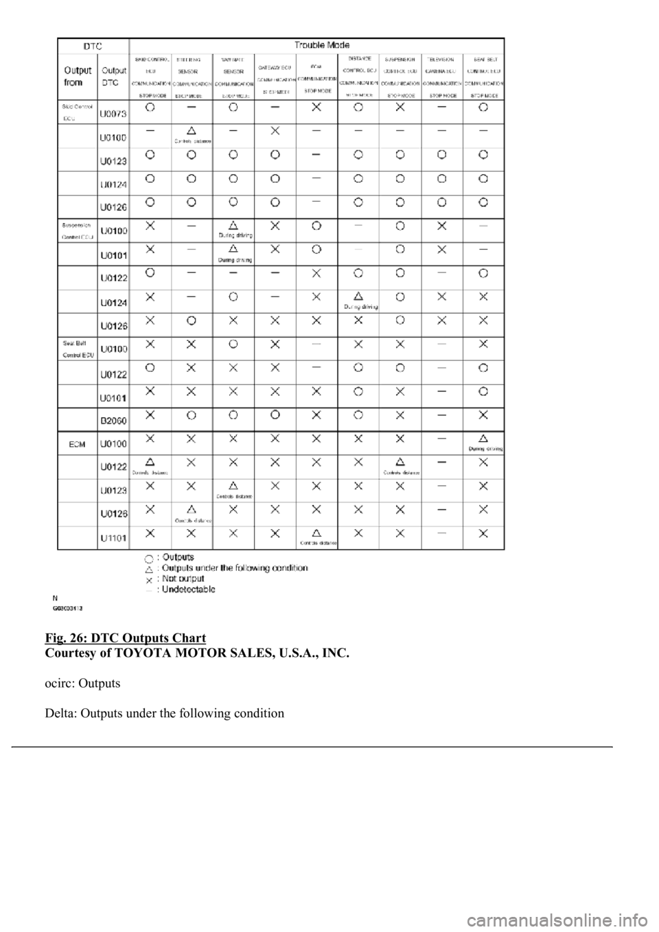
2.DTC COMBINATION TABLE
a. Perform troubleshooting according to the combination of DTCs output.
"CRUISE CONTROL" is
not displayed on the hand-
held tester via CAN VIM.ECU
COMMUNICATION
STOP MODEvehicles with
dynamic radar/laser
cruise control.ECU
COMMUNICATION
STOP MODE
"PSB" is not displayed on
the hand-held tester via
CAN VIM.SEAT BELT CONTROL
ECU
COMMUNICATION
STOP MODEApplicable only to
vehicles with a Pre-
collision safety
system.SEAT BELT CONTROL
ECU
COMMUNICATION
STOP MODE
"AIR SUSPENSION" is not
displayed on the hand-held
tester via CAN VIM.SUSPENSION
CONTROL ECU
COMMUNICATION
STOP MODEApplicable only to
vehicles with
electronic
modulated air
suspension.SUSPENSION
CONTROL ECU
COMMUNICATION
STOP MODE
"BODY/GATEWAY" is not
displayed on the hand-held
tester via CAN VIM.GATEWAY ECU
COMMUNICATION
STOP MODEApplicable to all
vehiclesGATEWAY ECU
COMMUNICATION
STOP MODE
"BACK GUIDE
MONITOR" is not displayed
on the hand-held tester via
CAN VIM.TELEVISION CAMERA
ECU
COMMUNICATION
STOP MODEApplicable only to
vehicles with a
LEXUS navigation
system.TELEVISION CAMERA
ECU
COMMUNICATION
STOP MODE
Page 1225 of 4500
Fig. 26: DTC Outputs Chart
Courtesy of TOYOTA MOTOR SALES, U.S.A., INC.
ocirc: Outputs
Delta: Outputs under the following condition
Page 1226 of 4500
x: Not output
-: Undetectable
HINT:
see SKID CONTROL ECU COMMUNICATION STOP MODE .
see STEERING SENSOR COMMUNICATION STOP MODE .
see YAW RATE SENSOR COMMUNICATION STOP MODE .
see GATEWAY ECU COMMUNICATION STOP MODE .
see ECM COMMUNICATION STOP MODE .
see DISTANCE CONTROL ECU COMMUNICATION STOP MODE .
see SUSPENSION CONTROL ECU COMMUNICATION STOP MODE .
see TELEVISION CAMERA ECU COMMUNICATION STOP MODE .
see SEAT BELT CONTROL ECU COMMUNICATION STOP MODE .
Page 1227 of 4500
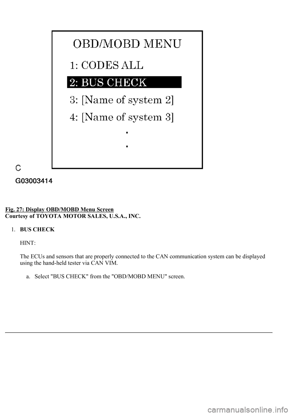
Fig. 27: Display OBD/MOBD Menu Screen
Courtesy of TOYOTA MOTOR SALES, U.S.A., INC.
1.BUS CHECK
HINT:
The ECUs and sensors that are properly connected to the CAN communication system can be displayed
using the hand-held tester via CAN VIM.
a. Select "BUS CHECK" from the "OBD/MOBD MENU" screen.
Page 1228 of 4500
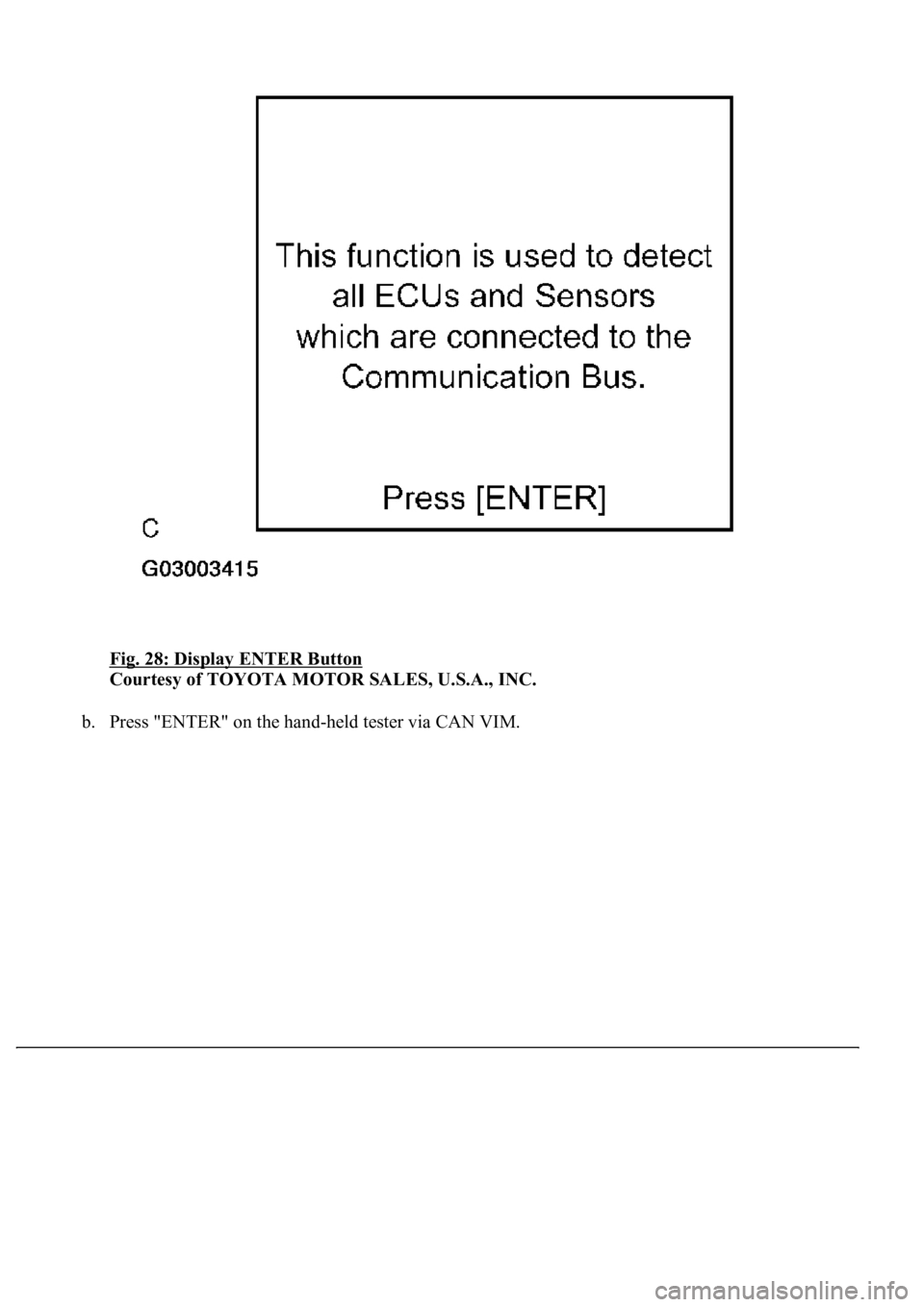
Fig. 28: Display ENTER Button
Courtesy of TOYOTA MOTOR SALES, U.S.A., INC.
b. Press "ENTER" on the hand-held tester via CAN VIM.
Page 1229 of 4500
Fig. 29: [Displays ECUs And Sensors]
Courtesy of TOYOTA MOTOR SALES, U.S.A., INC.
c. The screen displays the ECUs and sensors that are properly connected to the CAN communication
system.
HINT:
There is a communication stop in the system of any properly connected ECUs or sensors that are
not displayed (see CHECK CAN BUS LINE
).
2.CHECK FOR INSTALLED SYSTEMS (ECUS & SENSORS) THAT ADOPT CAN
COMMUNICATION
a. Systems (ECUs, sensors) that adopt CAN communication vary depending on the vehicle's optional
settin
gs. Check which systems (ECUs, sensors) are installed on the vehicle.
Page 1230 of 4500
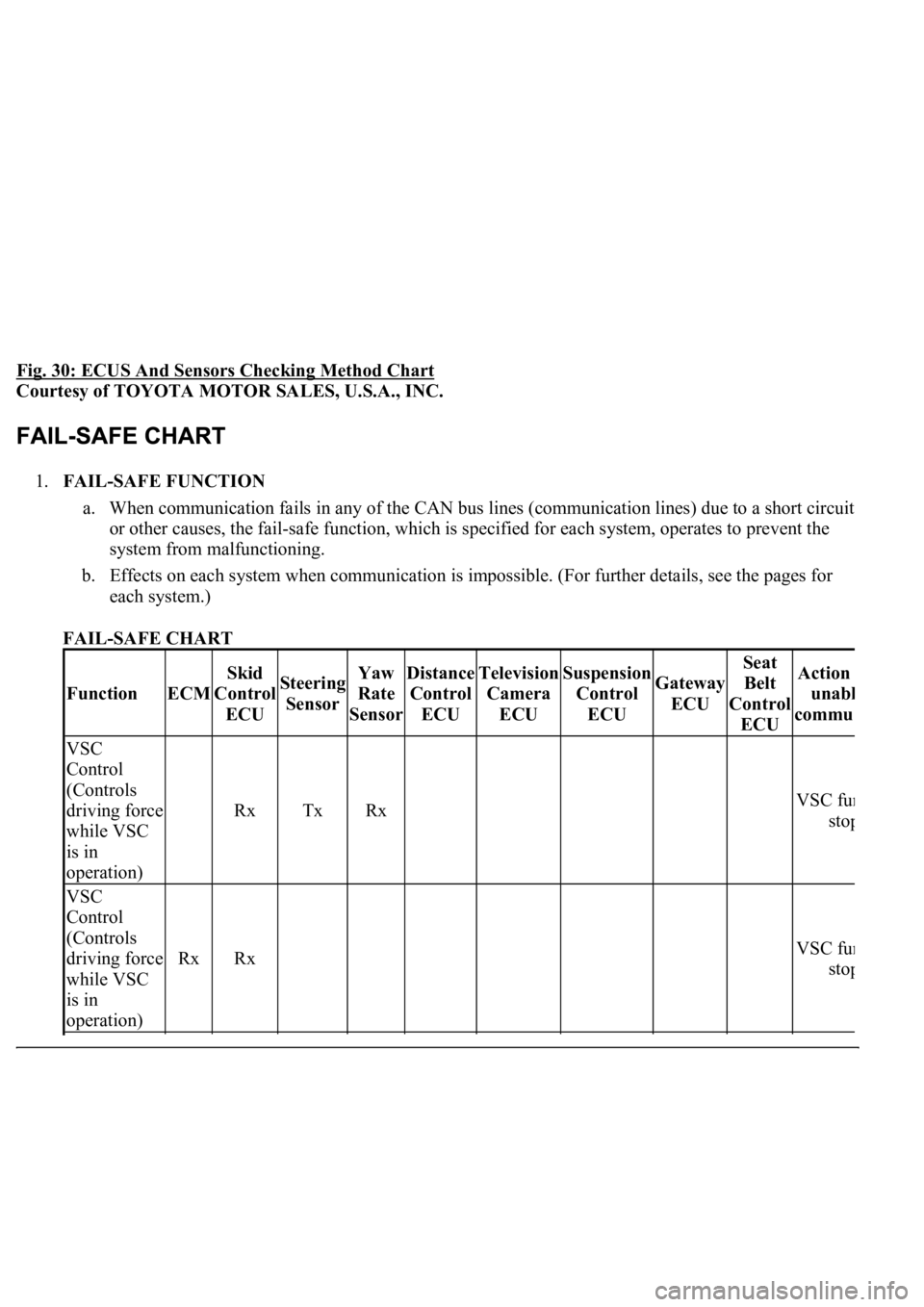
Fig. 30: ECUS And Sensors Checking Method Chart
Courtesy of TOYOTA MOTOR SALES, U.S.A., INC.
1.FAIL-SAFE FUNCTION
a. When communication fails in any of the CAN bus lines (communication lines) due to a short circuit
or other causes, the fail-safe function, which is specified for each system, operates to prevent the
system from malfunctioning.
b. Effects on each system when communication is impossible. (For further details, see the pages for
each system.)
FAIL-SAFE CHART
FunctionECM
Skid
Control
ECUSteering
SensorYaw
Rate
SensorDistance
Control
ECUTelevision
Camera
ECUSuspension
Control
ECUGateway
ECU
Seat
Belt
Control
ECUAction
unab
l
commu
VSC
Control
(Controls
driving force
while VSC
is in
operation)
RxTxRx VSC fun
stop
VSC
Control
(Controls
driving force
while VSC
is in
operation)
RxRx VSC fun
stop
Trending: Expansion Valve, fuel system, sat nav, evaporator removal, roof, injection, Ecu



![LEXUS LS430 2003 Factory Repair Manual Fig. 29: [Displays ECUs And Sensors]
Courtesy of TOYOTA MOTOR SALES, U.S.A., INC.
c. The screen displays the ECUs and sensors that are properly connected to the CAN communication
system.
HINT:
Th LEXUS LS430 2003 Factory Repair Manual Fig. 29: [Displays ECUs And Sensors]
Courtesy of TOYOTA MOTOR SALES, U.S.A., INC.
c. The screen displays the ECUs and sensors that are properly connected to the CAN communication
system.
HINT:
Th](/img/36/57050/w960_57050-1228.png)
