LEXUS LS430 2003 Factory Repair Manual
Manufacturer: LEXUS, Model Year: 2003,
Model line: LS430,
Model: LEXUS LS430 2003
Pages: 4500, PDF Size: 87.45 MB
LEXUS LS430 2003 Factory Repair Manual
LS430 2003
LEXUS
LEXUS
https://www.carmanualsonline.info/img/36/57050/w960_57050-0.png
LEXUS LS430 2003 Factory Repair Manual
Trending: brake light, AC Compressor control valve, turn signal, content, fog light, oil filter, headlamp
Page 1831 of 4500
Fig. 79: Identifying M4 And C12 Connector Terminals
Courtesy of TOYOTA MOTOR SALES, U.S.A., INC.
NG: REPAIR OR REPLACE HARNESS OR CONNECTOR
OK: REPLACE COMBINATION METER ASSY (SEE OVERHAUL
)
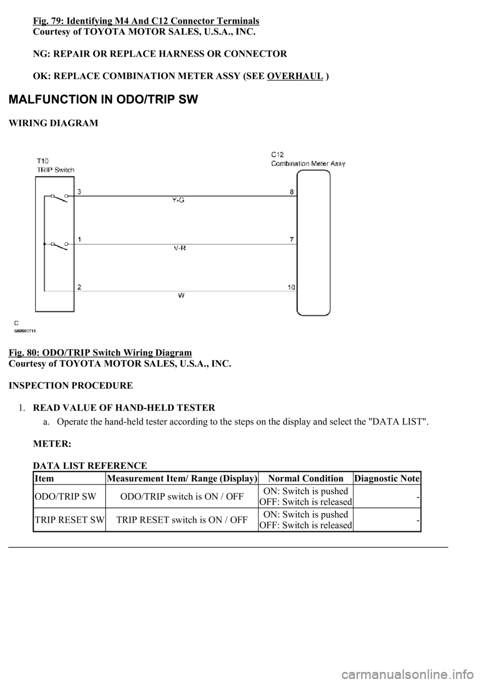
WIRING DIAGRAM
Fig. 80: ODO/TRIP Switch Wiring Diagram
Courtesy of TOYOTA MOTOR SALES, U.S.A., INC.
INSPECTION PROCEDURE
1.READ VALUE OF HAND-HELD TESTER
a. Operate the hand-held tester according to the steps on the display and select the "DATA LIST".
METER:
DATA LIST REFERENCE
ItemMeasurement Item/ Range (Display)Normal ConditionDiagnostic Note
ODO/TRIP SWODO/TRIP switch is ON / OFFON: Switch is pushed
OFF: Switch is released-
TRIP RESET SWTRIP RESET switch is ON / OFFON: Switch is pushed
OFF: Switch is released-
Page 1832 of 4500
OK:
Switch condition (ON/OFF) can be switched by actual operation.
NG: Go to step 2
OK: REPLACE COMBINATION METER ASSY (SEE OVERHAUL
)
2.INSPECT TRIP SWITCH
a. Disconnect the trip switch connector.
b. Measure the resistance according to the value (s) in the table below.
Standard
TRIP SWITCH CONNECTOR RESISTANCE SPECIFICATIONS
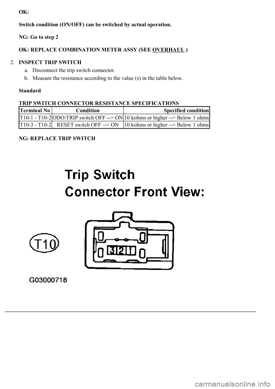
NG: REPLACE TRIP SWITCH
Terminal NoConditionSpecified condition
T10-1 - T10-2ODO/TRIP switch OFF --> ON10 kohms or higher --> Below 1 ohms
T10-3 - T10-2RESET switch OFF --> ON10 kohms or higher --> Below 1 ohms
Page 1833 of 4500
Fig. 81: Identifying Trip Switch Connector Terminals
Courtesy of TOYOTA MOTOR SALES, U.S.A., INC.
OK: GO TO NEXT STEP
3.CHECK HARNESS AND CONNECTOR (TRIP SWITCH - COMBINATION METER ASSY)
(SEE HOW TO PROCEED WITH TROUBLESHOOTING
)
a. Disconnect the C12 and T10 connectors.
b. Measure the resistance according to the value (s) in the table below.
Standard
C12 AND T10 CONNECTORS RESISTANCE SPECIFICATIONS
Tester ConnectionConditionSpecified Condition
C12-7 - T10-1AlwaysBelow 1 ohms
C12-8 - T10-3AlwaysBelow 1 ohms
C12-10 - T10-2AlwaysBelow 1 ohms
C12-7 - Body groundAlways10 kohms or higher
C12-8 - Body groundAlways10 kohms or higher
C12-10 - Body groundAlways10 kohms or higher
Page 1834 of 4500
Page 1835 of 4500
Fig. 82: Identifying C12 And T10 Connector Terminals
Courtesy of TOYOTA MOTOR SALES, U.S.A., INC.
NG: REPAIR OR REPLACE HARNESS OR CONNECTOR
OK: REPLACE COMBINATION METER ASSY (SEE OVERHAUL
)
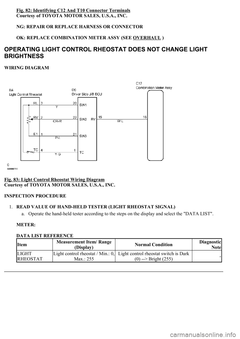
WIRING DIAGRAM
Fig. 83: Light Control Rheostat Wiring Diagram
Courtesy of TOYOTA MOTOR SALES, U.S.A., INC.
INSPECTION PROCEDURE
1.READ VALUE OF HAND-HELD TESTER (LIGHT RHEOSTAT SIGNAL)
a. Operate the hand-held tester according to the steps on the display and select the "DATA LIST".
METER:
DATA LIST REFERENCE
ItemMeasurement Item/ Range
(Display)Normal ConditionDiagnostic
Note
LIGHT
RHEOSTATLight control rheostat / Min.: 0,
Max.: 255Light control rheostat switch is Dark
(0) --> Bright (255)-
Page 1836 of 4500
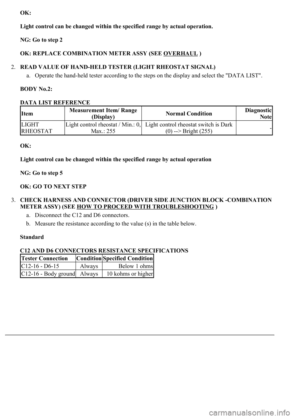
OK:
Light control can be changed within the specified range by actual operation.
NG: Go to step 2
OK: REPLACE COMBINATION METER ASSY (SEE OVERHAUL
)
2.READ VALUE OF HAND-HELD TESTER (LIGHT RHEOSTAT SIGNAL)
a. Operate the hand-held tester according to the steps on the display and select the "DATA LIST".
BODY No.2:
DATA LIST REFERENCE
OK:
Light control can be changed within the specified range by actual operation
NG: Go to step 5
OK: GO TO NEXT STEP
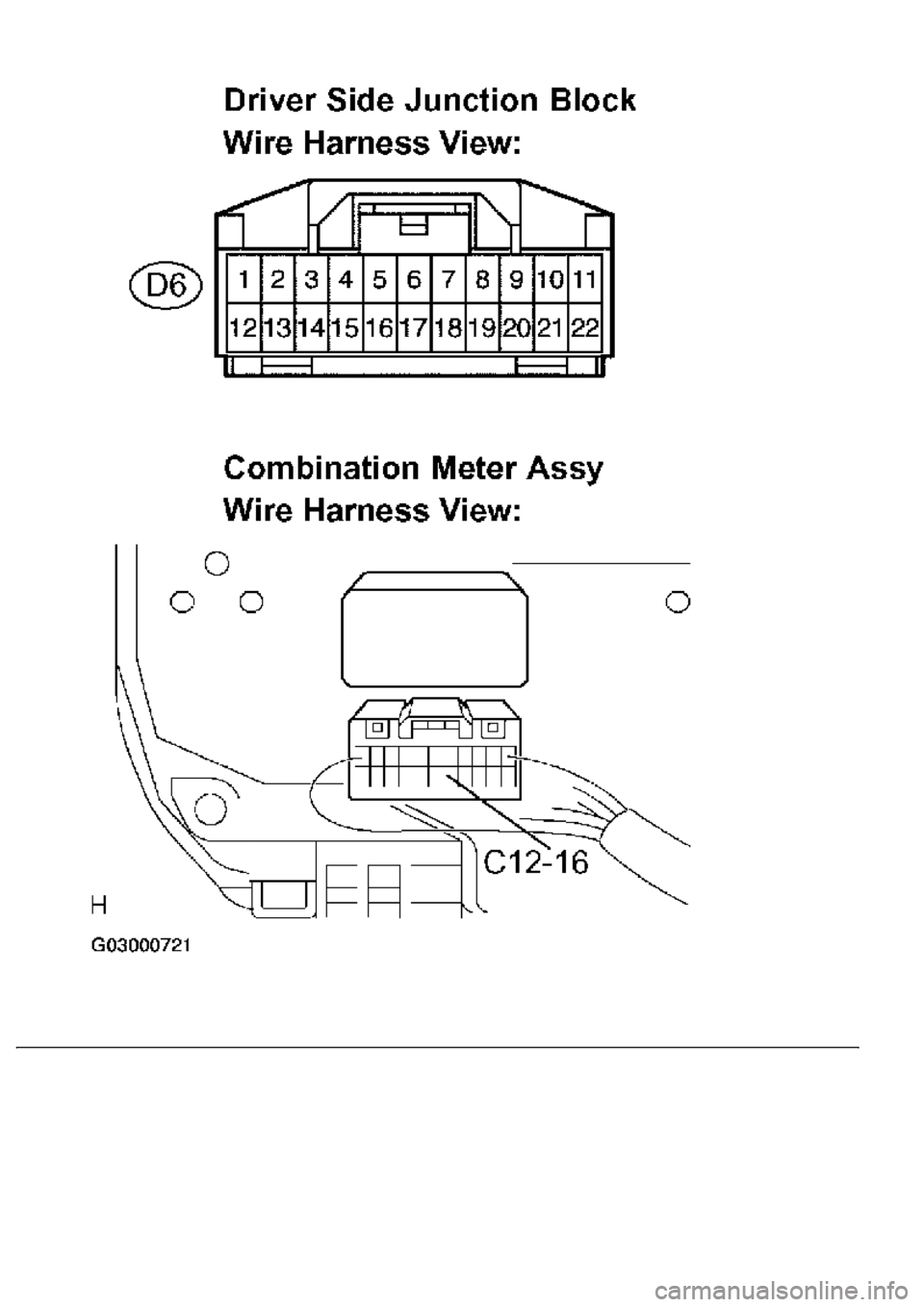
3.CHECK HARNESS AND CONNECTOR (DRIVER SIDE JUNCTION BLOCK -COMBINATION
METER ASSY) (SEE HOW TO PROCEED WITH TROUBLESHOOTING
)
a. Disconnect the C12 and D6 connectors.
b. Measure the resistance according to the value (s) in the table below.
Standard
C12 AND D6 CONNECTORS RESISTANCE SPECIFICATIONS
ItemMeasurement Item/ Range
(Display)Normal ConditionDiagnostic
Note
LIGHT
RHEOSTATLight control rheostat / Min.: 0,
Max.: 255Light control rheostat switch is Dark
(0) --> Bright (255)-
Tester ConnectionConditionSpecified Condition
C12-16 - D6-15AlwaysBelow 1 ohms
C12-16 - Body groundAlways10 kohms or higher
Page 1837 of 4500
Page 1838 of 4500
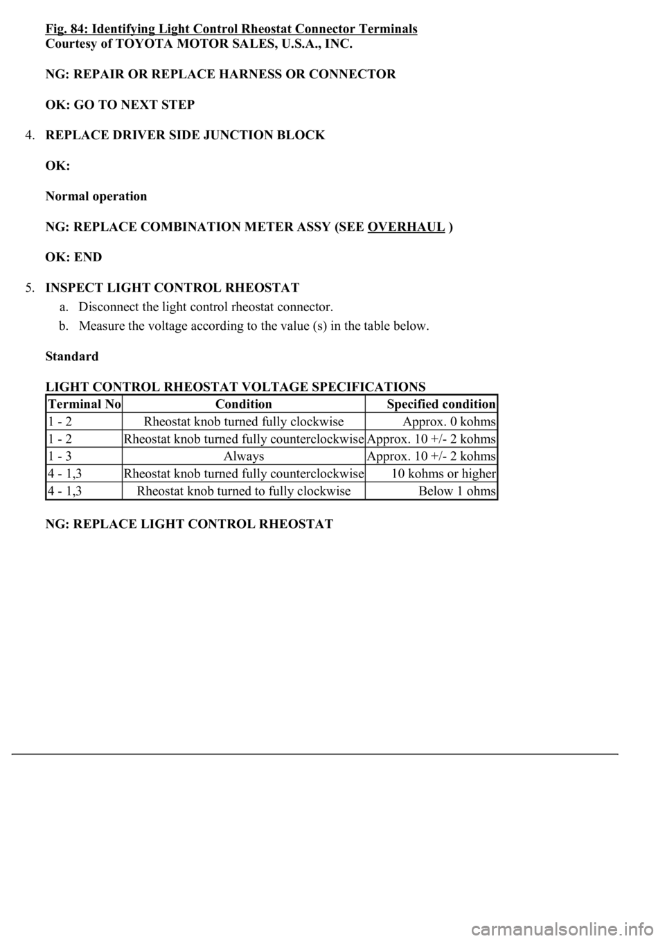
Fig. 84: Identifying Light Control Rheostat Connector Terminals
Courtesy of TOYOTA MOTOR SALES, U.S.A., INC.
NG: REPAIR OR REPLACE HARNESS OR CONNECTOR
OK: GO TO NEXT STEP
4.REPLACE DRIVER SIDE JUNCTION BLOCK
OK:
Normal operation
NG: REPLACE COMBINATION METER ASSY (SEE OVERHAUL
)
OK: END
5.INSPECT LIGHT CONTROL RHEOSTAT
a. Disconnect the light control rheostat connector.
b. Measure the voltage according to the value (s) in the table below.
Standard
LIGHT CONTROL RHEOSTAT VOLTAGE SPECIFICATIONS
NG: REPLACE LIGHT CONTROL RHEOSTAT
Terminal NoConditionSpecified condition
1 - 2Rheostat knob turned fully clockwiseApprox. 0 kohms
1 - 2Rheostat knob turned fully counterclockwiseApprox. 10 +/- 2 kohms
1 - 3AlwaysApprox. 10 +/- 2 kohms
4 - 1,3Rheostat knob turned fully counterclockwise10 kohms or higher
4 - 1,3Rheostat knob turned to fully clockwiseBelow 1 ohms
Page 1839 of 4500
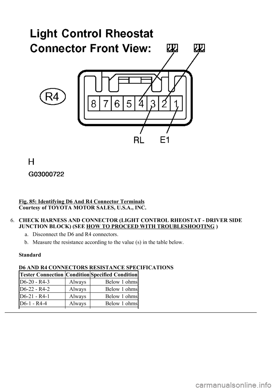
Fig. 85: Identifying D6 And R4 Connector Terminals
Courtesy of TOYOTA MOTOR SALES, U.S.A., INC.
6.CHECK HARNESS AND CONNECTOR (LIGHT CONTROL RHEOSTAT - DRIVER SIDE
JUNCTION BLOCK) (SEE HOW TO PROCEED WITH TROUBLESHOOTING
)
a. Disconnect the D6 and R4 connectors.
b. Measure the resistance according to the value (s) in the table below.
Standard
D6 AND R4 CONNECTORS RESISTANCE SPECIFICATIONS
Tester ConnectionConditionSpecified Condition
D6-20 - R4-3AlwaysBelow 1 ohms
D6-22 - R4-2AlwaysBelow 1 ohms
D6-21 - R4-1AlwaysBelow 1 ohms
D6-1 - R4-4AlwaysBelow 1 ohms
Page 1840 of 4500
NG: REPAIR OR REPLACE HARNESS OR CONNECTOR
R4-3 - Body groundAlways10 kohms or higher
R4-2 - Body groundAlways10 kohms or higher
R4-1 - Body groundAlways10 kohms or higher
R4-4 - Body groundAlways10 kohms or higher
Trending: power steering fluid, steering interlock cable, keyless, air condition, oil temperature, lane assist, Absorber suspension
