LEXUS LS430 2003 Factory Repair Manual
Manufacturer: LEXUS, Model Year: 2003,
Model line: LS430,
Model: LEXUS LS430 2003
Pages: 4500, PDF Size: 87.45 MB
LEXUS LS430 2003 Factory Repair Manual
LS430 2003
LEXUS
LEXUS
https://www.carmanualsonline.info/img/36/57050/w960_57050-0.png
LEXUS LS430 2003 Factory Repair Manual
Trending: spark plugs replace, change time, steering interlock cable, engine, trunk, c1336, Sp1
Page 1871 of 4500
Fig. 20: Installing Water Inlet Housing
Courtesy of TOYOTA MOTOR SALES, U.S.A., INC.
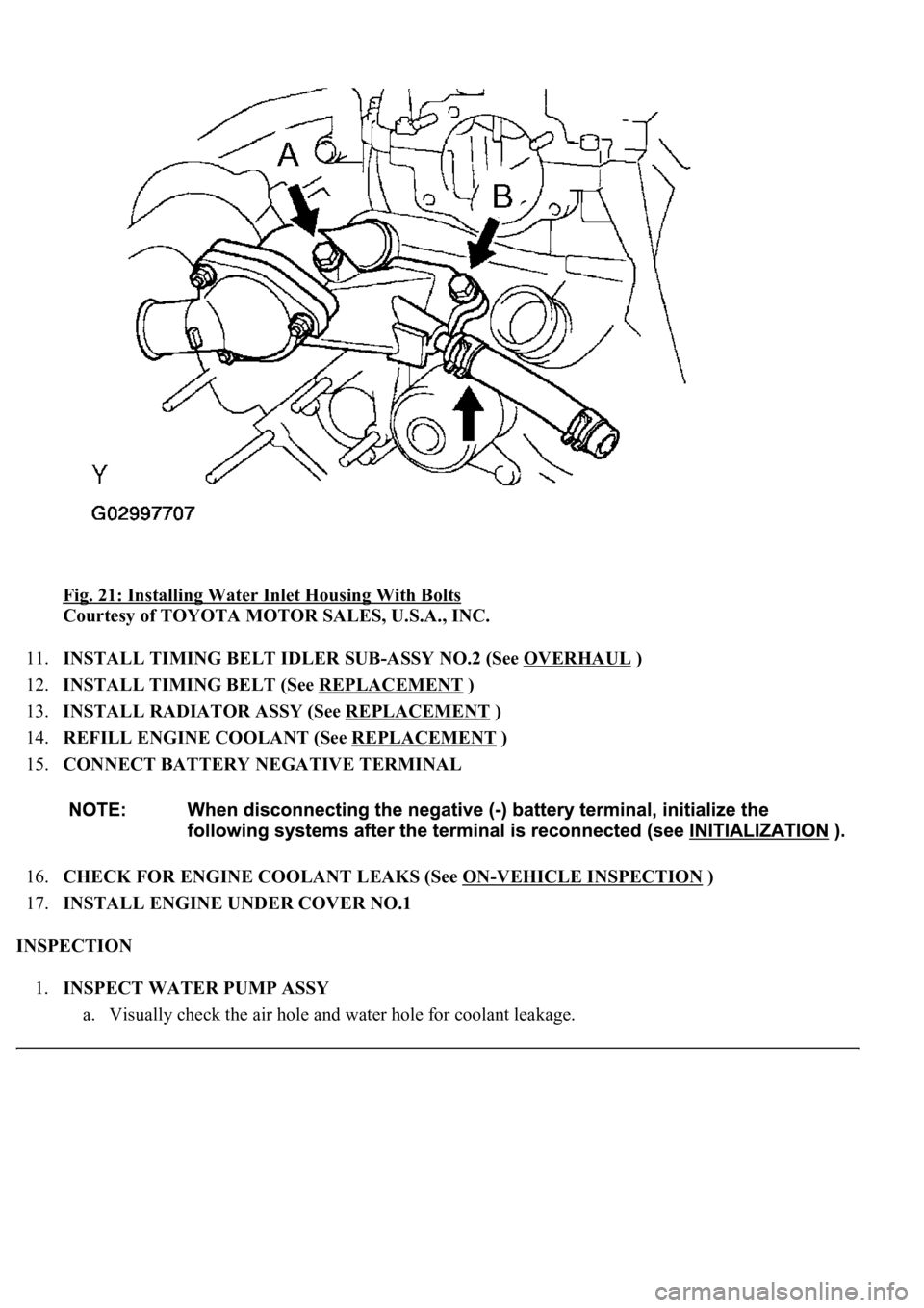
10.INSTALL WATER INLET HOUSING
a. Install a new O-ring.
b. Apply soapy water to the O-ring.
c. Apply seal packing to the groove of the water inlet housing as shown in the illustration.
Seal packing: Part No. 08826-00100 or equivalent
d. Install the water inlet housing with the 2 bolts. Then connect the water hose.
Bolt length:
75 mm (2.95 in.) for bolt A
25 mm (0.98 in.) for bolt B
Page 1872 of 4500
Fig. 21: Installing Water Inlet Housing With Bolts
Courtesy of TOYOTA MOTOR SALES, U.S.A., INC.
11.INSTALL TIMING BELT IDLER SUB-ASSY NO.2 (See OVERHAUL
)
12.INSTALL TIMING BELT (See REPLACEMENT
)
13.INSTALL RADIATOR ASSY (See REPLACEMENT
)
14.REFILL ENGINE COOLANT (See REPLACEMENT
)
15.CONNECT BATTERY NEGATIVE TERMINAL
16.CHECK FOR ENGINE COOLANT LEAKS (See ON
-VEHICLE INSPECTION )
17.INSTALL ENGINE UNDER COVER NO.1
INSPECTION
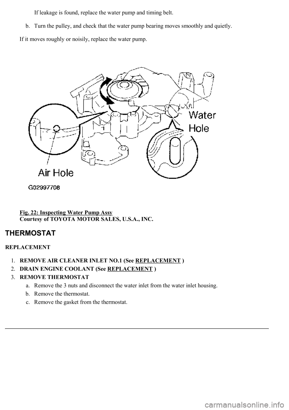
1.INSPECT WATER PUMP ASSY
a. Visuall
y<00030046004b00480046004e00030057004b004800030044004c00550003004b0052004f004800030044005100470003005a00440057004800550003004b0052004f004800030049005200550003004600520052004f0044005100570003004f0048004400
4e0044[ge.
Page 1873 of 4500
If leakage is found, replace the water pump and timing belt.
b. Turn the pulley, and check that the water pump bearing moves smoothly and quietly.
If it moves roughly or noisily, replace the water pump.
Fig. 22: Inspecting Water Pump Assy
Courtesy of TOYOTA MOTOR SALES, U.S.A., INC.
REPLACEMENT
1.REMOVE AIR CLEANER INLET NO.1 (See REPLACEMENT
)
2.DRAIN ENGINE COOLANT (See REPLACEMENT
)
3.REMOVE THERMOSTAT
a. Remove the 3 nuts and disconnect the water inlet from the water inlet housing.
b. Remove the thermostat.
c. Remove the
gasket from the thermostat.
Page 1874 of 4500
Fig. 23: Removing Nuts
Courtesy of TOYOTA MOTOR SALES, U.S.A., INC.
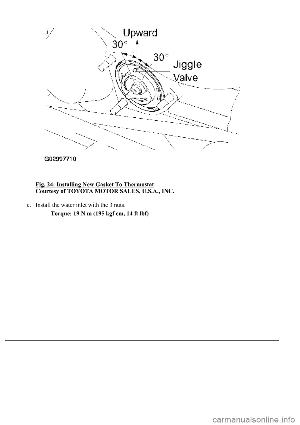
4.INSTALL THERMOSTAT
a. Install a new gasket to the thermostat.
b. Insert the thermostat into the water inlet housing with the jiggle valve facing straight upward.
HINT:
The
jiggle valve may be set within 30° of either side of the prescribed position.
Page 1875 of 4500
Fig. 24: Installing New Gasket To Thermostat
Courtesy of TOYOTA MOTOR SALES, U.S.A., INC.
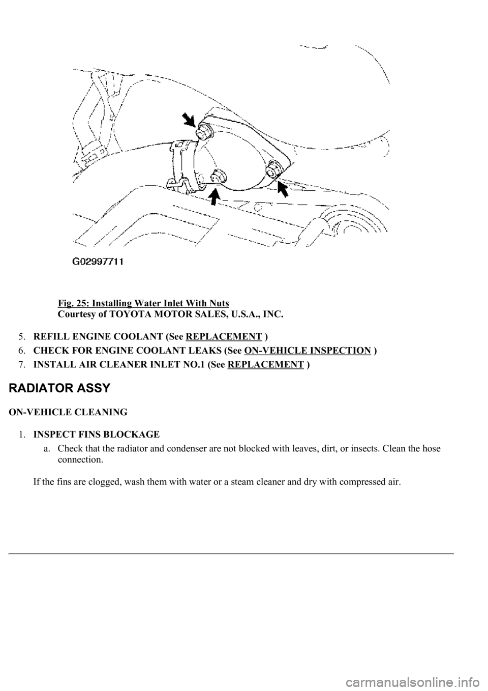
c. Install the water inlet with the 3 nuts.
Torque: 19 N m (195 kgf cm, 14 ft lbf)
Page 1876 of 4500
Fig. 25: Installing Water Inlet With Nuts
Courtesy of TOYOTA MOTOR SALES, U.S.A., INC.
5.REFILL ENGINE COOLANT (See REPLACEMENT
)
6.CHECK FOR ENGINE COOLANT LEAKS (See ON
-VEHICLE INSPECTION )
7.INSTALL AIR CLEANER INLET NO.1 (See REPLACEMENT
)
ON-VEHICLE CLEANING
1.INSPECT FINS BLOCKAGE
a. Check that the radiator and condenser are not blocked with leaves, dirt, or insects. Clean the hose
connection.
If the fins are clo
gged, wash them with water or a steam cleaner and dry with compressed air.
Page 1877 of 4500
Fig. 26: Inspecting Fins Blockage
Courtesy of TOYOTA MOTOR SALES, U.S.A., INC.
STANDARD SPECIFICATION
If the fins are bent, straighten them with a screwdriver or pliers.
Never apply water directly onto the electronic components.
COMPONENTS
Injection DistanceInjection Pressure
300 mm(11.81 in.)2,942 to 4,903 kPa (30 to 50 kgf cm2 , 427 to 711 psi)
500 mm (19.69 in.)4,903 to 7,845 kPa (50to80kgf cm2 , 711 to 1,138 psi)
Page 1878 of 4500
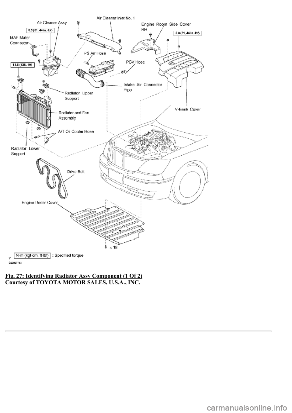
Fig. 27: Identifying Radiator Assy Component (1 Of 2)
Courtesy of TOYOTA MOTOR SALES, U.S.A., INC.
Page 1879 of 4500
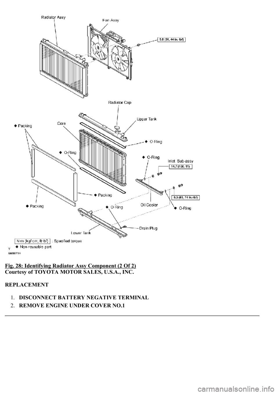
Fig. 28: Identifying Radiator Assy Component (2 Of 2)
Courtesy of TOYOTA MOTOR SALES, U.S.A., INC.
REPLACEMENT
1.DISCONNECT BATTERY NEGATIVE TERMINAL
2.REMOVE ENGINE UNDER COVER NO.1
Page 1880 of 4500
3.REMOVE AIR CLEANER INLET NO.1
4.DRAIN ENGINE COOLANT (See REPLACEMENT
)
5.REMOVE V-BANK COVER
6.REMOVE INTAKE AIR CONNECTOR PIPE
7.DISCONNECT RADIATOR HOSE NO.1
8.DISCONNECT RADIATOR HOSE NO.2
9.DISCONNECT OIL COOLER INLET TUBE NO.1
10.DISCONNECT OIL COOLER OUTLET TUBE NO.1
11.REMOVE AIR CLEANER ASSY
12.REMOVE RADIATOR AND FAN ASSEMBLY
a. Disconnect the cooling fan ECU connector.
b. Remove the 2 nuts and 2 radiator upper supports.
c. Remove the radiator and fan assembly.
d. Remove the 2 radiator lower supports.
Fig. 29: Removing Nuts And Radiator Upper Supports
Courtesy of TOYOTA MOTOR SALES, U.S.A., INC.
Trending: lane assist, reset, window regulator, warning light, Bean, camshaft service, charging

