LEXUS LS430 2003 Factory Repair Manual
Manufacturer: LEXUS, Model Year: 2003,
Model line: LS430,
Model: LEXUS LS430 2003
Pages: 4500, PDF Size: 87.45 MB
LEXUS LS430 2003 Factory Repair Manual
LS430 2003
LEXUS
LEXUS
https://www.carmanualsonline.info/img/36/57050/w960_57050-0.png
LEXUS LS430 2003 Factory Repair Manual
Trending: snow chains, oil filter, B2419 bean, Conditioner, radio antenna, fuel pump, lights
Page 1851 of 4500
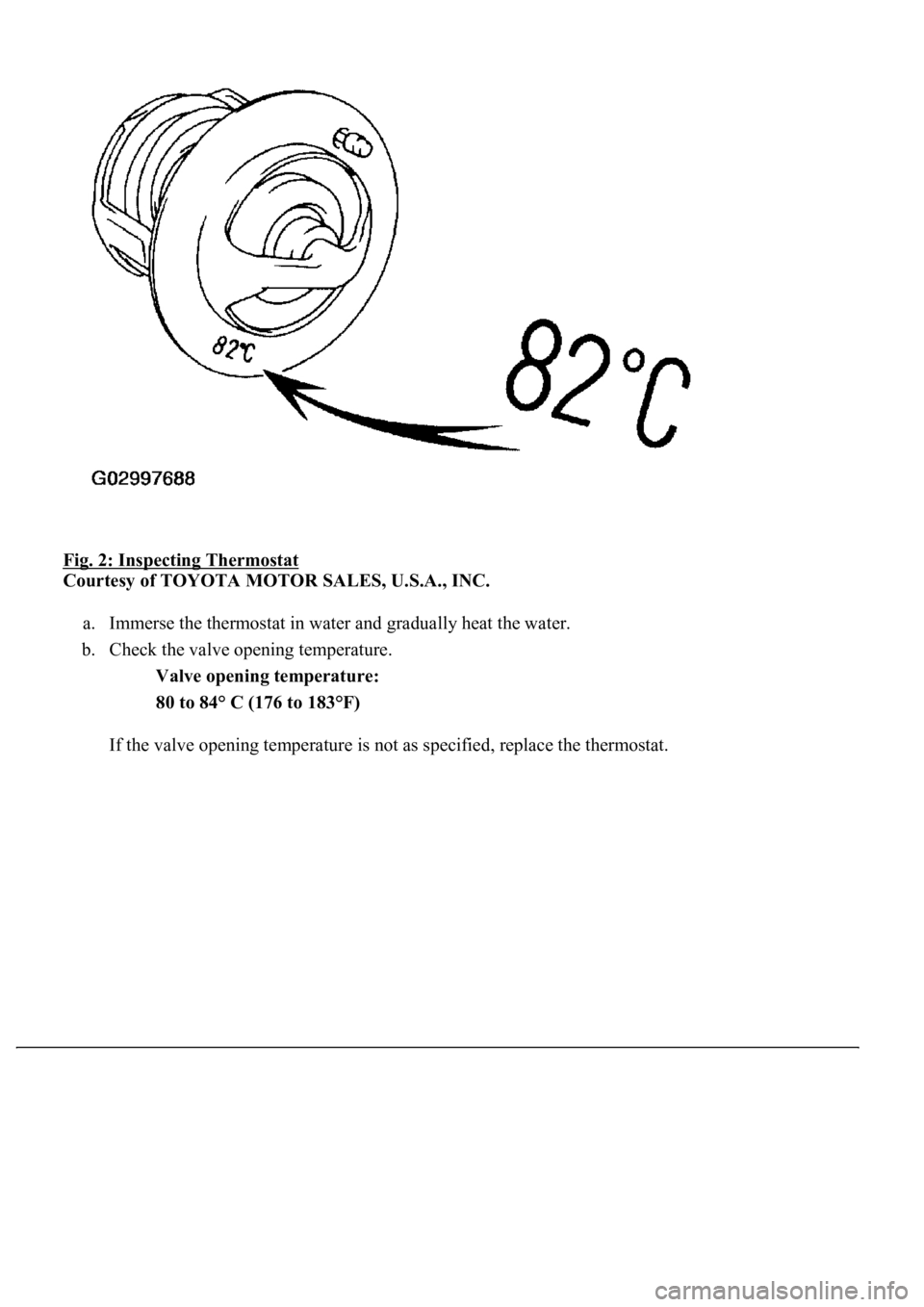
Fig. 2: Inspecting Thermostat
Courtesy of TOYOTA MOTOR SALES, U.S.A., INC.
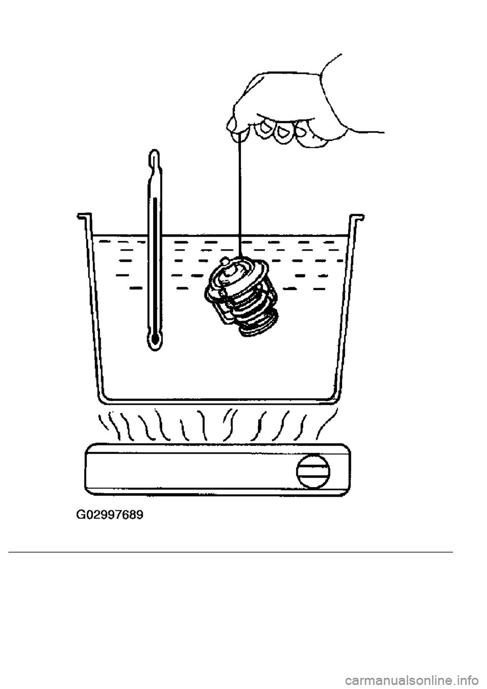
a. Immerse the thermostat in water and gradually heat the water.
b. Check the valve opening temperature.
Valve opening temperature:
80 to 84° C (176 to 183°F)
If the valve openin
g<0003005700480050005300480055004400570058005500480003004c0056000300510052005700030044005600030056005300480046004c0049004c00480047000f0003005500480053004f00440046004800030057004b004800030057004b0048005500
500052005600570044005700110003[
Page 1852 of 4500
Page 1853 of 4500
Fig. 3: Checking Valve Opening Temperature
Courtesy of TOYOTA MOTOR SALES, U.S.A., INC.
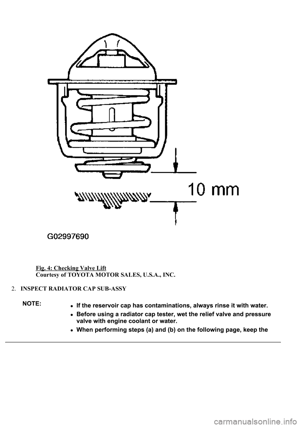
c. Check the valve lift.
Valve lift: 10 mm (0.39 in.) or more at 95°C (203°F)
If the valve lift is not as specified, replace the thermostat.
d. Check that the valve is fully closed when the thermostat is at low temperatures (below 40°C (104°
F)).
If not closed, replace the thermostat.
Page 1854 of 4500
Fig. 4: Checking Valve Lift
Courtesy of TOYOTA MOTOR SALES, U.S.A., INC.
2.INSPECT RADIATOR CAP SUB-ASSY
Page 1855 of 4500
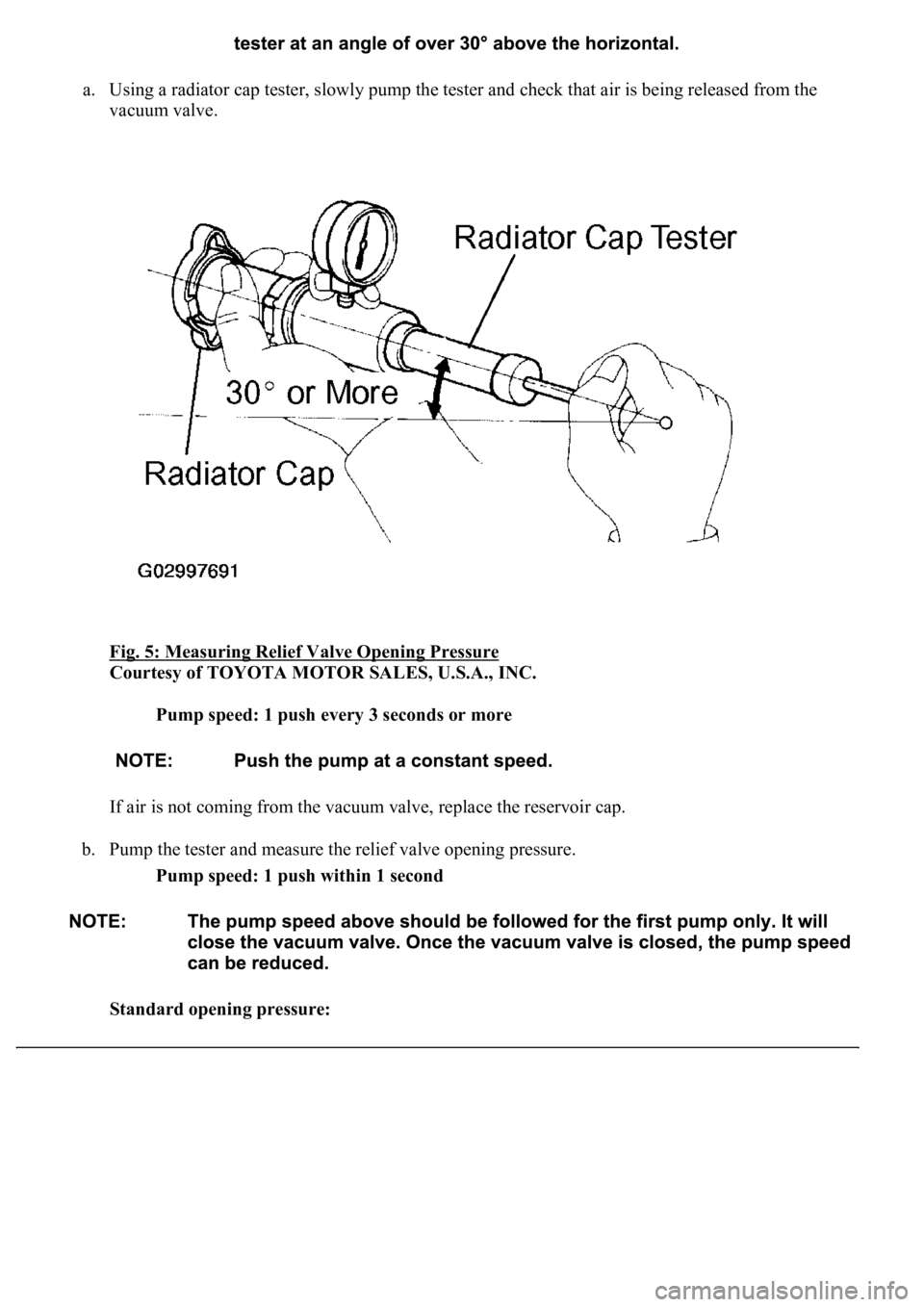
a. Using a radiator cap tester, slowly pump the tester and check that air is being released from the
vacuum valve.
Fig. 5: Measuring Relief Valve Opening Pressure
Courtesy of TOYOTA MOTOR SALES, U.S.A., INC.
Pump speed: 1 push every 3 seconds or more
If air is not coming from the vacuum valve, replace the reservoir cap.
b. Pump the tester and measure the relief valve opening pressure.
Pump speed: 1 push within 1 second
Standard opening pressure:
Page 1856 of 4500
93 to 123 kPa (0.95 to 1.25 kgf/cm2 , 13.5 to 17.8 psi)
Minimum opening pressure:
78 kPa (0.78 kgf/cm
2 , 11.4 psi)
HINT:
Pay attention to the tester's maximum reading of the opening pressure. If the maximum reading is less
than the minimum opening pressure above, replace the reservoir cap.
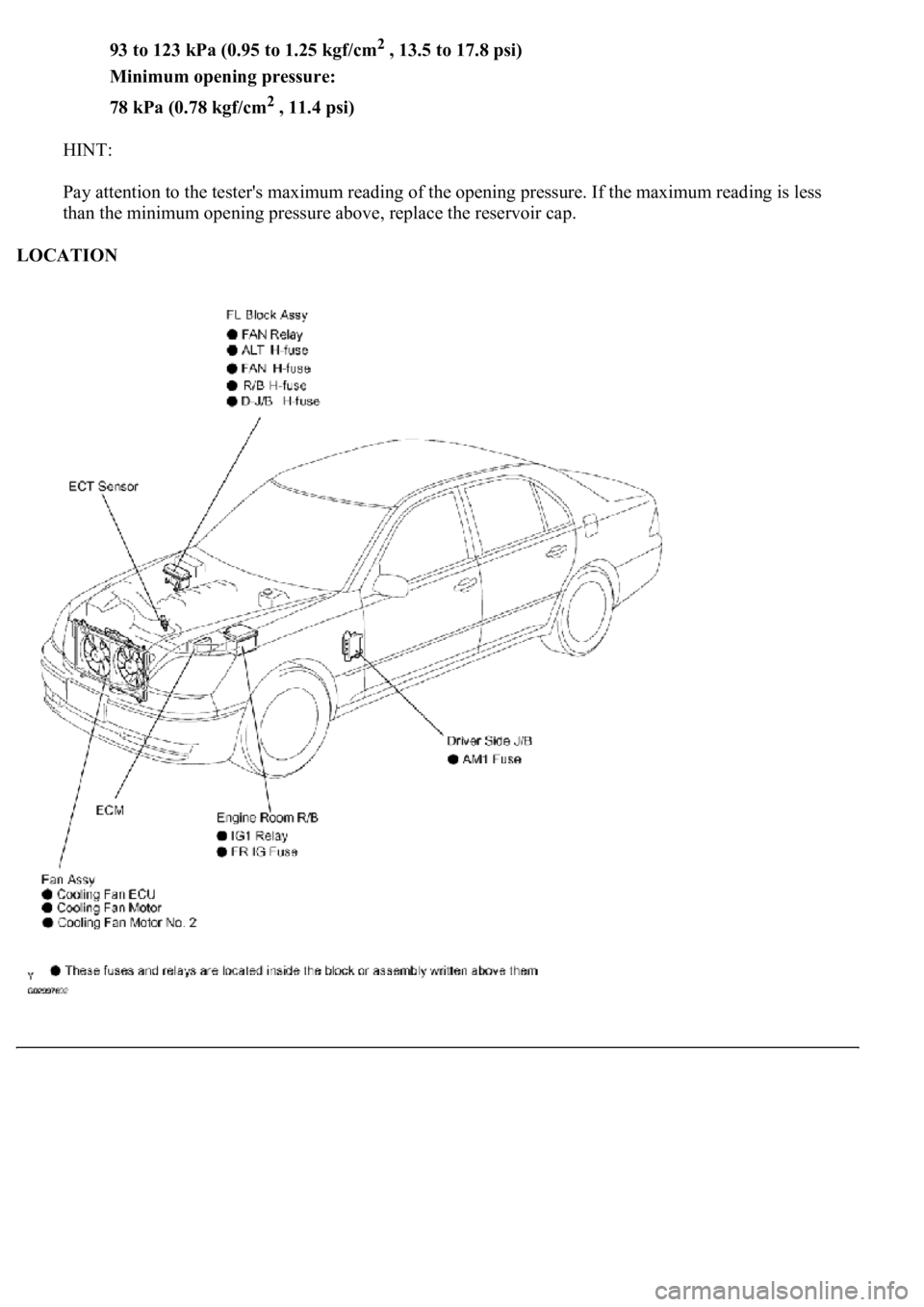
LOCATION
Page 1857 of 4500
Fig. 6: Identifying Cooling Fan System Component Location
Courtesy of TOYOTA MOTOR SALES, U.S.A., INC.
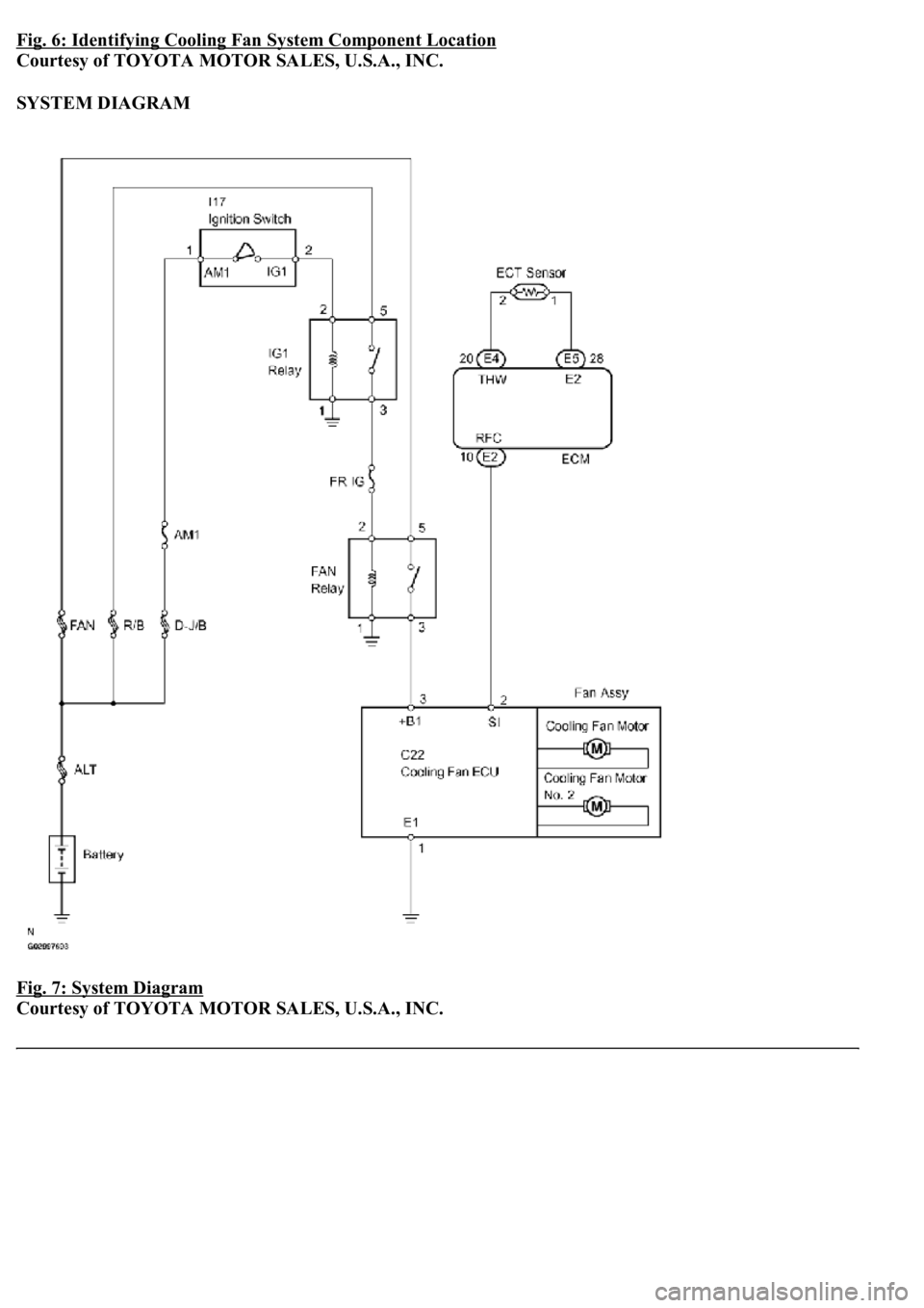
SYSTEM DIAGRAM
Fig. 7: System Diagram
Courtesy of TOYOTA MOTOR SALES, U.S.A., INC.
Page 1858 of 4500
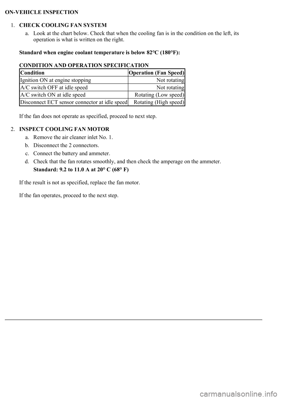
ON-VEHICLE INSPECTION
1.CHECK COOLING FAN SYSTEM
a. Look at the chart below. Check that when the cooling fan is in the condition on the left, its
operation is what is written on the right.
Standard when engine coolant temperature is below 82°C (180°F):
CONDITION AND OPERATION SPECIFICATION
If the fan does not operate as specified, proceed to next step.
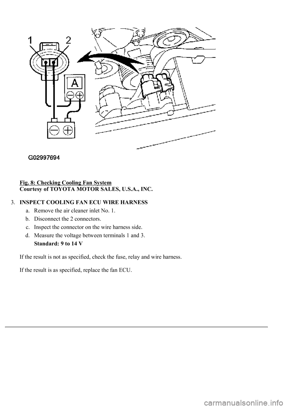
2.INSPECT COOLING FAN MOTOR
a. Remove the air cleaner inlet No. 1.
b. Disconnect the 2 connectors.
c. Connect the battery and ammeter.
d. Check that the fan rotates smoothly, and then check the amperage on the ammeter.
Standard: 9.2 to 11.0 A at 20° C (68° F)
If the result is not as specified, replace the fan motor.
If the fan operates, proceed to the next step.
ConditionOperation (Fan Speed)
Ignition ON at engine stoppingNot rotating
A/C switch OFF at idle speedNot rotating
A/C switch ON at idle speedRotating (Low speed)
Disconnect ECT sensor connector at idle speedRotating (High speed)
Page 1859 of 4500
Fig. 8: Checking Cooling Fan System
Courtesy of TOYOTA MOTOR SALES, U.S.A., INC.
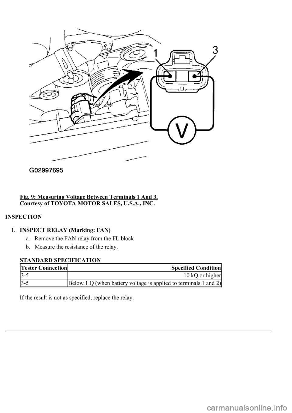
3.INSPECT COOLING FAN ECU WIRE HARNESS
a. Remove the air cleaner inlet No. 1.
b. Disconnect the 2 connectors.
c. Inspect the connector on the wire harness side.
d. Measure the voltage between terminals 1 and 3.
Standard: 9 to 14 V
If the result is not as specified, check the fuse, relay and wire harness.
If the result is as specified, replace the fan ECU.
Page 1860 of 4500
Fig. 9: Measuring Voltage Between Terminals 1 And 3.
Courtesy of TOYOTA MOTOR SALES, U.S.A., INC.
INSPECTION
1.INSPECT RELAY (Marking: FAN)
a. Remove the FAN relay from the FL block
b. Measure the resistance of the relay.
STANDARD SPECIFICATION
If the result is not as specified, replace the rela
y.
Tester ConnectionSpecified Condition
3-510 kQ or higher
3-5Below 1 Q (when battery voltage is applied to terminals 1 and 2)
Trending: wiring diagram, Compressor control valve, keys, service schedule, wipers, c1336, automatic transmission
