LEXUS LS430 2003 Factory Repair Manual
Manufacturer: LEXUS, Model Year: 2003,
Model line: LS430,
Model: LEXUS LS430 2003
Pages: 4500, PDF Size: 87.45 MB
LEXUS LS430 2003 Factory Repair Manual
LS430 2003
LEXUS
LEXUS
https://www.carmanualsonline.info/img/36/57050/w960_57050-0.png
LEXUS LS430 2003 Factory Repair Manual
Trending: navigation update, pcv, trailer, exhaust manifold, trunk, Expansion Valve, fuse
Page 1881 of 4500
13.REMOVE FAN ASSY
a. Disconnect the radiator reservoir hose from the radiator.
b. Remove the 6 bolts and fan.
14.INSTALL FAN ASSY
a. Install the fan with the 6 bolts.
Torque: 5.0 Nm (51 kgfcm, 44 in.lbf)
b. Connect the radiator reservoir hose to the radiator.
15.INSTALL RADIATOR AND FAN ASSEMBLY
a. Install the 2 radiator lower supports to the radiator.
b. Attach the 2 radiator lower supports on the radiator to the body bracket.
c. Install the radiator and fan assembly with the 2 radiator upper supports and 2 nuts.
Torque: 13.5 N m (138 kgf cm, 10 ft lbf)
d. Connect the cooling fan ECU connector.
16.INSTALL AIR CLEANER ASSY
17.INSTALL AIR CLEANER INLET NO.1
18.REFILL ENGINE COOLANT (See REPLACEMENT
)
19.CHECK FOR ENGINE COOLANT LEAKS
20.INSTALL ENGINE UNDER COVER NO.1
21.CONNECT BATTERY NEGATIVE TERMINAL
OVERHAUL
1.REMOVE PACKING
2.REMOVE RADIATOR CAP SUB-ASSY
3.REMOVE DRAIN PLUG
a. Remove the drain plug.
b. Remove the O-ring.
4.ASSEMBLE SST
SST 09230-01010
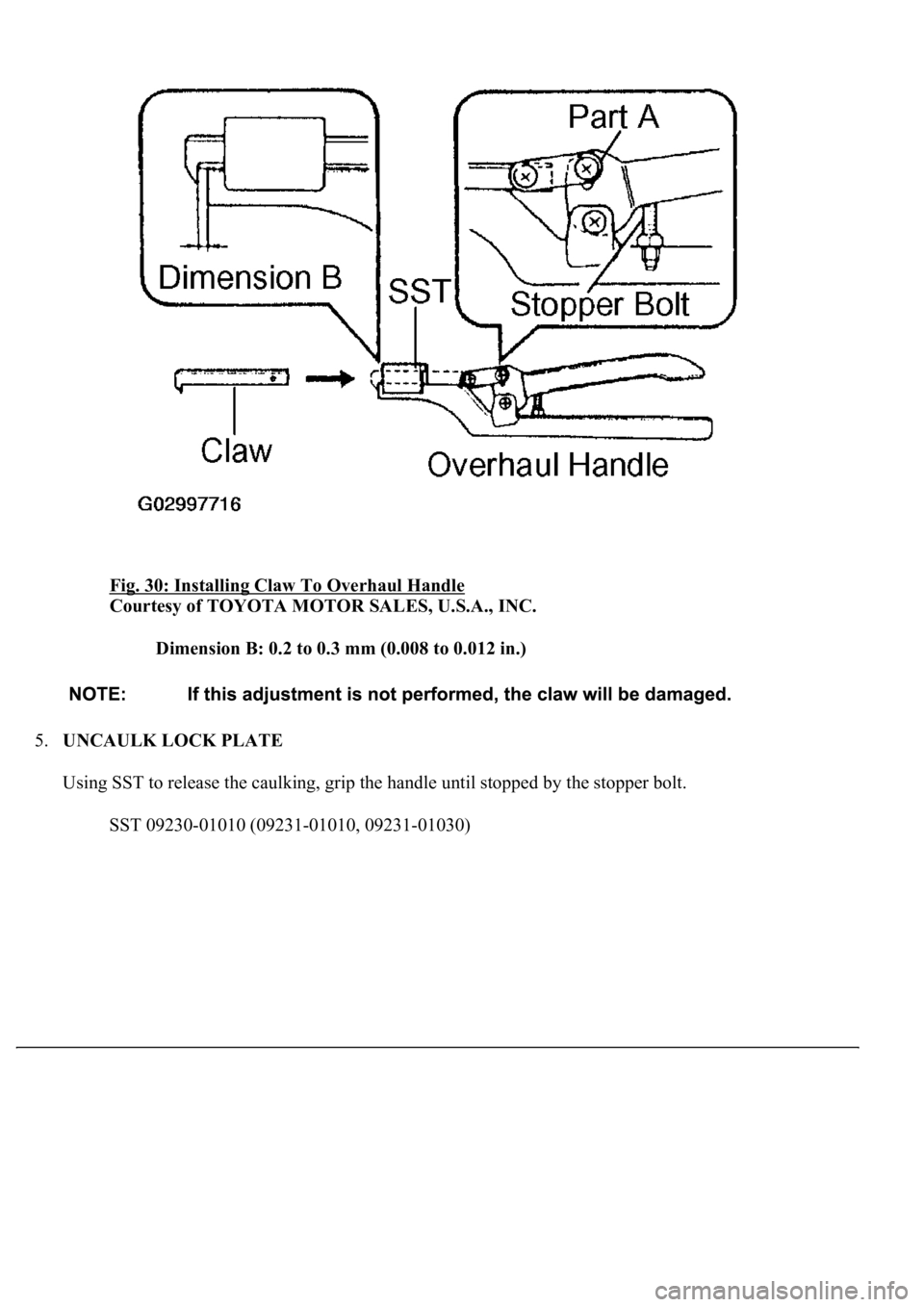
a. Install the claw to the overhaul handle, inserting it in the hole in part A as shown in the illustration
b. While gripping the handle, adjust the stopper bolt so that dimension B is as shown in the
illustration.
Page 1882 of 4500
Fig. 30: Installing Claw To Overhaul Handle
Courtesy of TOYOTA MOTOR SALES, U.S.A., INC.
Dimension B: 0.2 to 0.3 mm (0.008 to 0.012 in.)
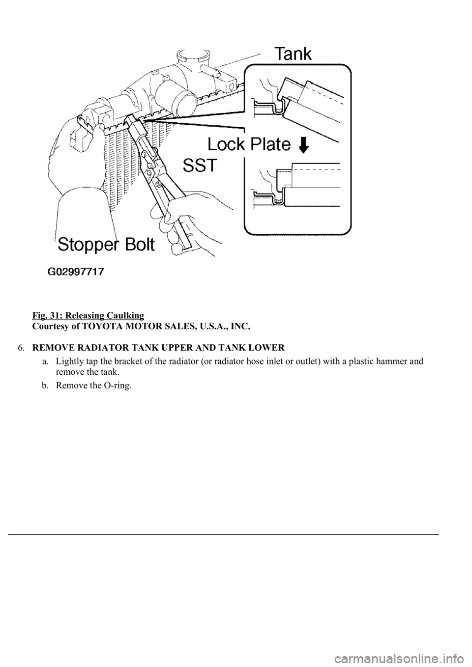
5.UNCAULK LOCK PLATE
Using SST to release the caulking, grip the handle until stopped by the stopper bolt.
SST 09230-01010 (09231-01010, 09231-01030)
Page 1883 of 4500
Fig. 31: Releasing Caulking
Courtesy of TOYOTA MOTOR SALES, U.S.A., INC.
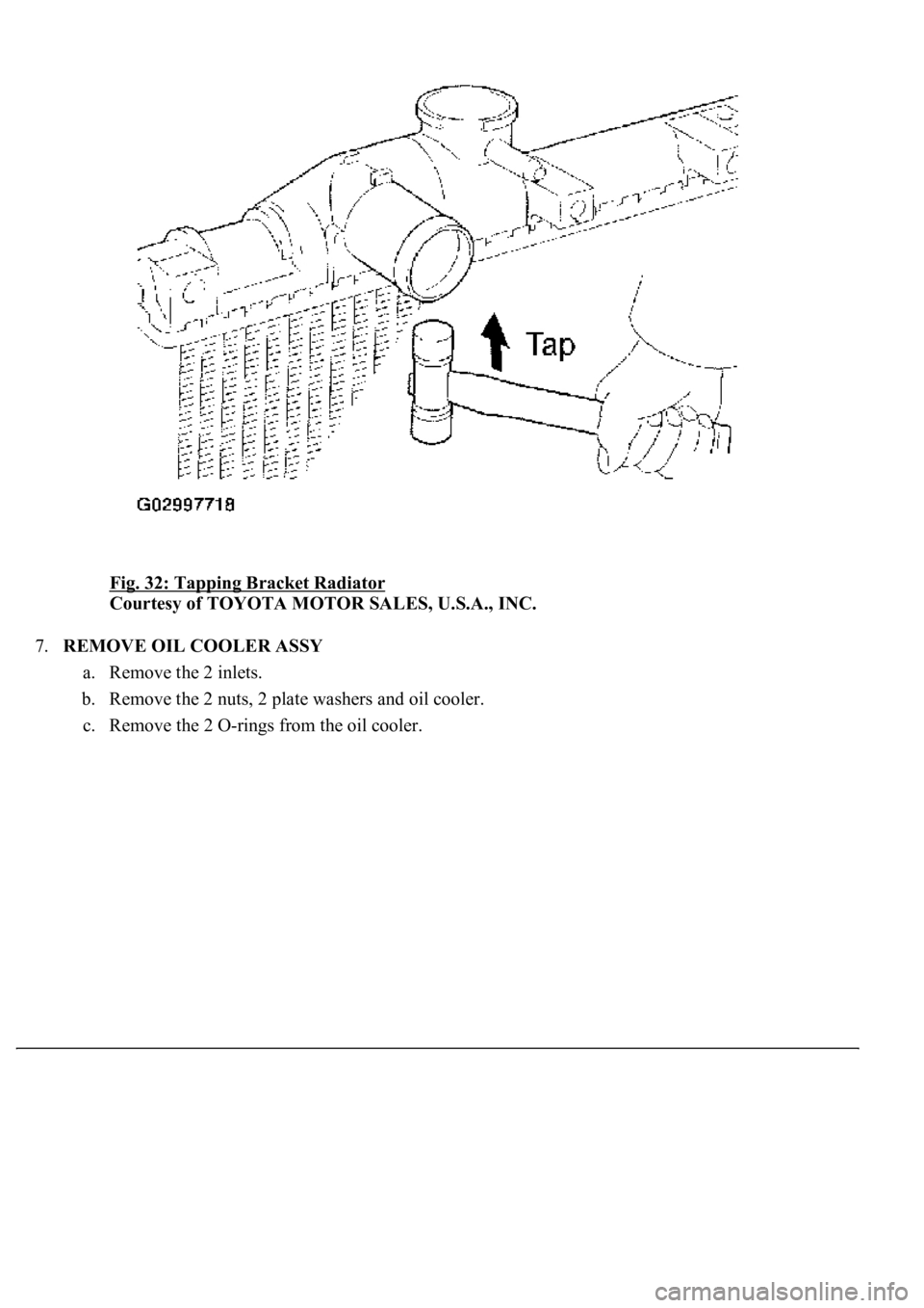
6.REMOVE RADIATOR TANK UPPER AND TANK LOWER
a. Lightly tap the bracket of the radiator (or radiator hose inlet or outlet) with a plastic hammer and
remove the tank.
b. Remove the O-ring.
Page 1884 of 4500
Fig. 32: Tapping Bracket Radiator
Courtesy of TOYOTA MOTOR SALES, U.S.A., INC.
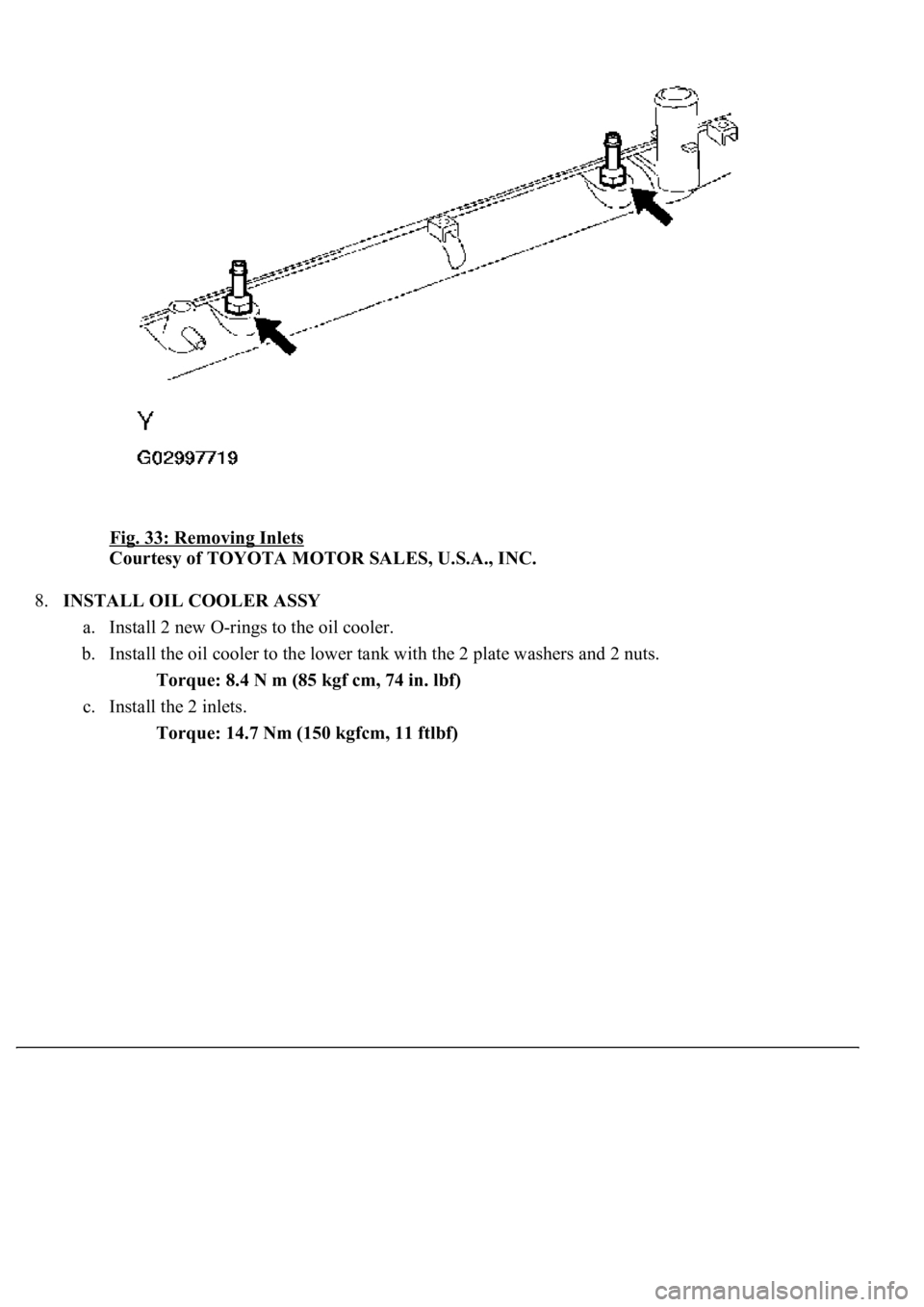
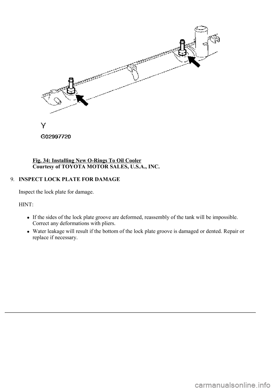
7.REMOVE OIL COOLER ASSY
a. Remove the 2 inlets.
b. Remove the 2 nuts, 2 plate washers and oil cooler.
c. Remove the 2 O-rin
gs from the oil cooler.
Page 1885 of 4500
Fig. 33: Removing Inlets
Courtesy of TOYOTA MOTOR SALES, U.S.A., INC.
8.INSTALL OIL COOLER ASSY
a. Install 2 new O-rings to the oil cooler.
b. Install the oil cooler to the lower tank with the 2 plate washers and 2 nuts.
Torque: 8.4 N m (85 kgf cm, 74 in. lbf)
c. Install the 2 inlets.
Torque: 14.7 Nm (150 kgfcm, 11 ftlbf)
Page 1886 of 4500
Fig. 34: Installing New O-Rings To Oil Cooler
Courtesy of TOYOTA MOTOR SALES, U.S.A., INC.
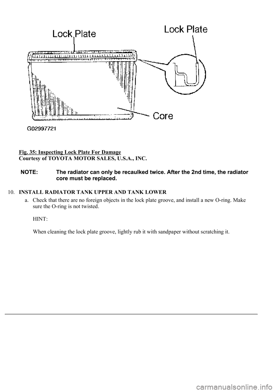
9.INSPECT LOCK PLATE FOR DAMAGE
Inspect the lock plate for damage.
HINT:
If the sides of the lock plate groove are deformed, reassembly of the tank will be impossible.
Correct any deformations with pliers.
Water leakage will result if the bottom of the lock plate groove is damaged or dented. Repair or
replace if necessar
y.
Page 1887 of 4500
Fig. 35: Inspecting Lock Plate For Damage
Courtesy of TOYOTA MOTOR SALES, U.S.A., INC.
10.INSTALL RADIATOR TANK UPPER AND TANK LOWER
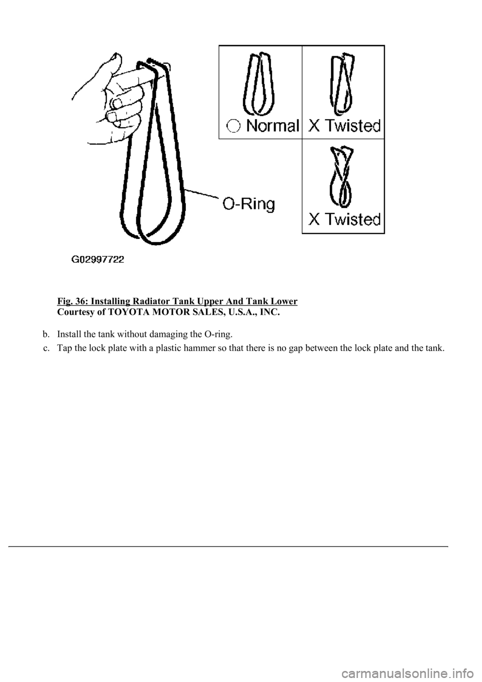
a. Check that there are no foreign objects in the lock plate groove, and install a new O-ring. Make
sure the O-ring is not twisted.
HINT:
When cleanin
g the lock plate groove, lightly rub it with sandpaper without scratching it.
Page 1888 of 4500
Fig. 36: Installing Radiator Tank Upper And Tank Lower
Courtesy of TOYOTA MOTOR SALES, U.S.A., INC.
b. Install the tank without damaging the O-ring.
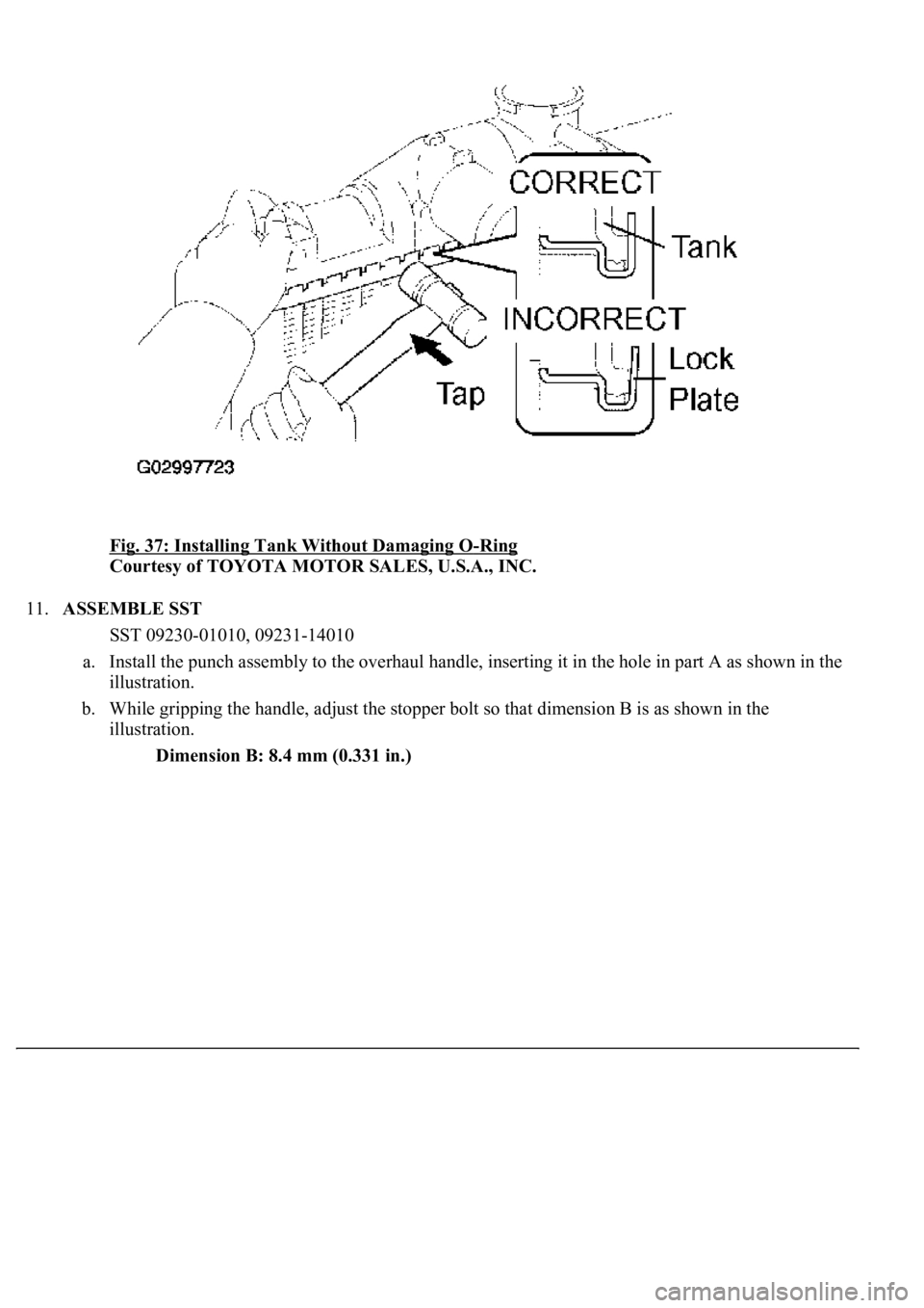
c. Tap the lock plate with a plastic hammer so that there is no
gap between the lock plate and the tank.
Page 1889 of 4500
Fig. 37: Installing Tank Without Damaging O-Ring
Courtesy of TOYOTA MOTOR SALES, U.S.A., INC.
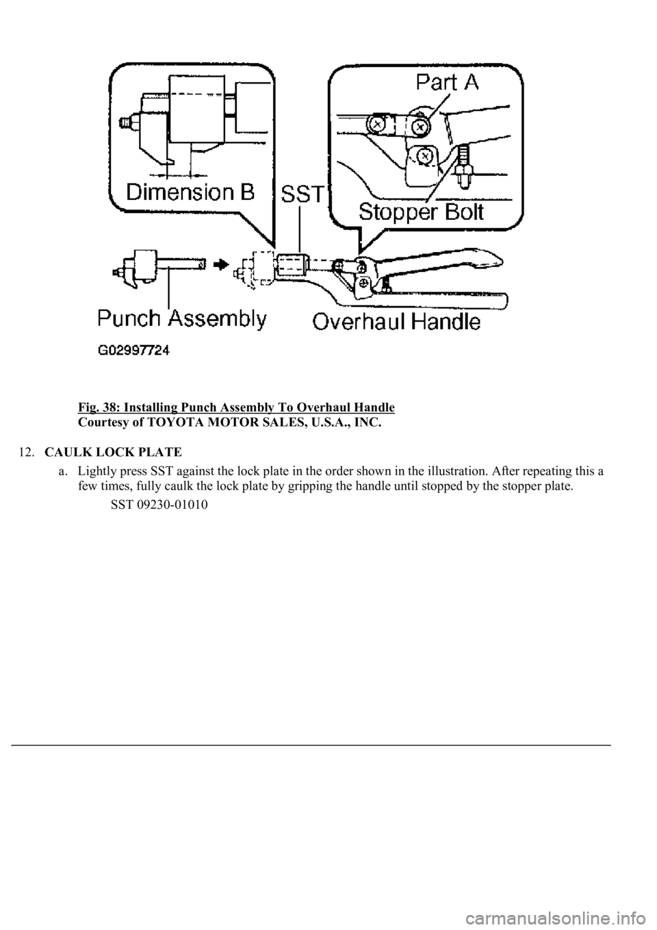
11.ASSEMBLE SST
SST 09230-01010, 09231-14010
a. Install the punch assembly to the overhaul handle, inserting it in the hole in part A as shown in the
illustration.
b. While gripping the handle, adjust the stopper bolt so that dimension B is as shown in the
illustration.
Dimension B: 8.4 mm (0.331 in.)
Page 1890 of 4500
Fig. 38: Installing Punch Assembly To Overhaul Handle
Courtesy of TOYOTA MOTOR SALES, U.S.A., INC.
12.CAULK LOCK PLATE
a. Lightly press SST against the lock plate in the order shown in the illustration. After repeating this a
few times, fully caulk the lock plate by gripping the handle until stopped by the stopper plate.
SST 09230-01010
Trending: fuses, length, battery replacement, keys, check transmission fluid, fuel consumption, radiator

