LEXUS LS430 2003 Factory Repair Manual
Manufacturer: LEXUS, Model Year: 2003, Model line: LS430, Model: LEXUS LS430 2003Pages: 4500, PDF Size: 87.45 MB
Page 1901 of 4500
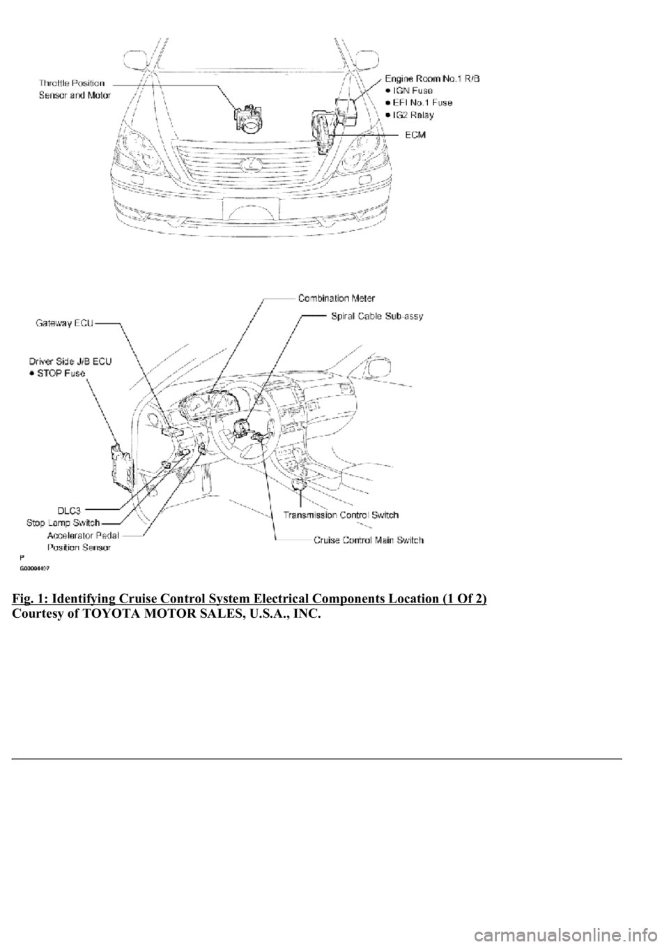
Fig. 1: Identifying Cruise Control System Electrical Components Location (1 Of 2)
Courtesy of TOYOTA MOTOR SALES, U.S.A., INC.
Page 1902 of 4500
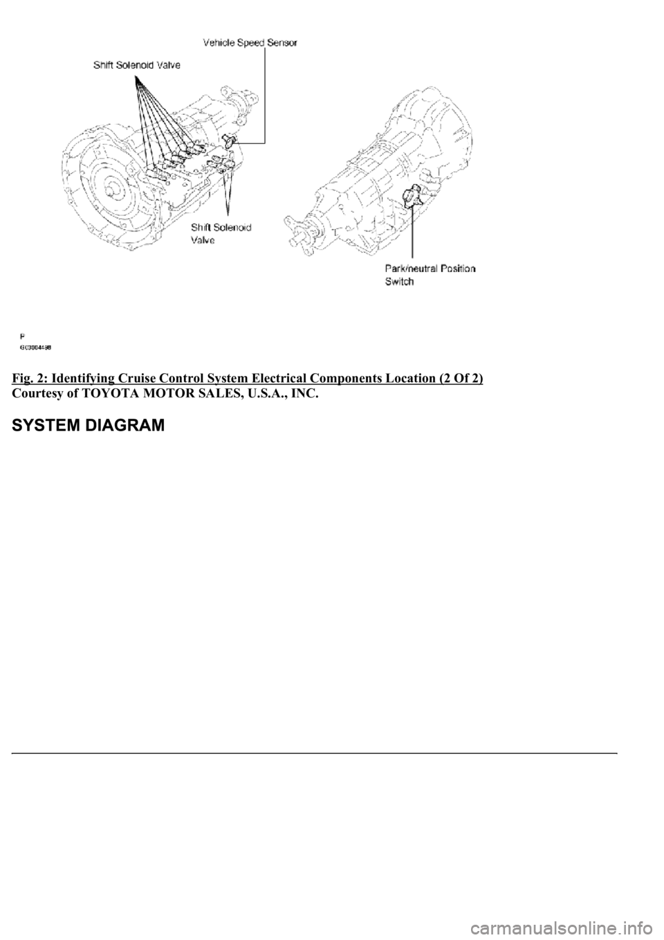
Fig. 2: Identifying Cruise Control System Electrical Components Location (2 Of 2)
Courtesy of TOYOTA MOTOR SALES, U.S.A., INC.
Page 1903 of 4500
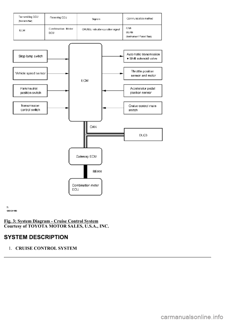
Fig. 3: System Diagram - Cruise Control System
Courtesy of TOYOTA MOTOR SALES, U.S.A., INC.
1.CRUISE CONTROL SYSTEM
Page 1904 of 4500

The computer which controls the cruise control system is combined with the ECM, and the actuator uses
the throttle position sensor and motor. A microcomputer is built into the ECM to control functions
including: ON-OFF, SET/COAST, RESUME/ACCEL, CANCEL, vehicle speed operation, motor output
control, and overdrive control.
The ECM compares the driving vehicle speed from the speed sensor with the stored vehicle speed
set through the cruise control main switch assy. The ECM instructs the throttle valve motor of the
throttle position sensor and motor to close the valve when the driving vehicle speed is greater than
the stored vehicle speed, and instructs it to open the valve when the driving speed is less than the
stored speed.
The ECM receives signals such as ON-OFF, SET/COAST, RESUME/ACCEL, and CANCEL from
the cruise control main switch assy and executes them.
The ECM turns on the indicator in the combination meter based upon the ON signal from the cruise
control main switch assy.
The ECM cancels the cruise control system when it detects that the brake pedal is depressed, based
on the stop lamp switch signal.
The ECM cancels the cruise control system when it detects that the shift position is changed from
D (6th, 5th or 4th gear) to N (3rd, 2nd or 1st gear), based on the park/neutral position switch assy
signal.
2.LIMIT CONTROL
a. Low speed limit
The lowest possible limit of the speed setting range is set at approximately 40 km/h (25 mph). The
cruise control system cannot be set when the driving vehicle speed is below the low speed limit.
Cruise control operation will be automatically canceled and the stored vehicle speed will be erased
when the vehicle speed goes below the low speed limit while the cruise control is in operation.
b. High speed limit
The highest possible limit of the speed setting range is set at approximately 200 km/h (125 mph).
The cruise control system cannot be set when the driving vehicle speed is over the high speed limit.
Speed up using RESUME/ACCEL with the cruise control main switch assy also cannot be set
beyond the high speed limit.
3.OPERATION OF CRUISE CONTROL
The cruise control main switch operates seven functions: SET, COAST, TAP-DOWN, RESUME,
ACCEL, TAP-UP, and CANCEL. The SET, TAP-DOWN and COAST functions, and the RESUME,
TAP-UP and ACCEL functions are operated with the same switch. The cruise control main switch assy is
an automatic return type switch which turns on only while operating it in each arrow direction and turns
off after releasing it.
a. SET CONTROL
Vehicle speed is stored and constant speed control is maintained when pushing the switch to SET/
COAST while drivin
g with the cruise control main switch ON-OFF button on (the CRUISE main
Page 1905 of 4500
indicator light is on), and the vehicle speed is within the set speed range (between the low and high
speed limits).
b. COAST CONTROL
The ECM makes the cruise control demanding throttle opening angle zero degrees and decelerates
the vehicle (the throttle valve is not fully closed due to idle speed control, etc.) when SET/COAST
on the cruise control main switch is pressed and held while the cruise control system is in
operation. Vehicle speed, when the cruise control main switch is released from SET/COAST, is
stored and constant speed control is maintained.
c. TAP-DOWN CONTROL
When tapping down on the cruise control main switch to SET/COAST (for approximately 0.5
second) while the cruise control system is in operation, the stored vehicle speed decreases each
time by approximately 1.6 km/h (1.0 mph). However, when the difference between the driving and
the stored vehicle speed is more than 5 km/h (approximately 3.1 mph), the vehicle speed, when the
cruise control main switch is released from SET/COAST, will be stored and constant speed control
is maintained.
d. ACCELERATION CONTROL
The throttle valve motor of the throttle position sensor and motor is instructed by the ECM to open
<0057004b0048000300590044004f005900480003005a004b00480051000300350028003600380030002800120024002600260028002f00030052005100030057004b00480003004600550058004c005600480003004600520051005700550052004f000300
500044004c005100030056005a004c00570046004b0003004c[s pressed and held while the
cruise control system is in operation. Vehicle speed, when the cruise control main switch is
released from RESUME/ACCEL, is stored and the vehicle is controlled at a constant speed.
e. TAP-UP CONTROL
When tapping up on the cruise control main switch to RESUME/ACCEL (for approximately 0.5
second) while the cruise control system is in operation, the stored vehicle speed increases each time
by approximately 1.6 km/h (1.0 mph). However, when the difference between the driving and the
stored vehicle speed is more than 5 km/h (approximately 3.1 mph), the stored vehicle speed will not
be changed.
f. RESUME CONTROL
If cruise control operation was cancelled with the stop lamp switch or the CANCEL switch, and if
driving speed is within the limit range, pushing the cruise control main switch to
RESUME/ACCEL restores vehicle speed memorized at the time of cancellation, and maintains
constant speed control.
g. MANUAL CANCEL CONTROL
Doing any of the following cancels the cruise control system while in operation. (The stored vehicle
speed in the ECM is maintained.)
Depressing the brake pedal
Page 1906 of 4500
Moving the shift lever to any position except D (6th, 5th and 4th gears)
Pushing the cruise control main switch to CANCEL
Pushing the cruise control main switch ON-OFF button off (The stored vehicle speed in the ECM is
not maintained.)
4.AUTO CANCEL (FAIL-SAFE)
This system has an automatic cancellation function (fail-safe) (for details, see FAIL
-SAFE CHART ).
The hand-held tester can be used at steps 4, 5, 6, 7, and 12.
1.VEHICLE BROUGHT TO WORK SHOP
2.(SEE CUSTOMER PROBLEM ANALYSIS CHECK
)
3.PROBLEM SYMPTOM CONFIRMATION
4.CHECK BODY MULTIPLEX COMMUNICATION SYSTEM (SEE HOW TO PROCEED WITH
TROUBLESHOOTING )
a. Check for output DTCs.
HINT:
The ECM of this system is connected to the multiplex communication system. Therefore, before starting
troubleshooting, make sure to check that there is no trouble in the multiplex communication system.
MULTIPLEX SYSTEM DTC IS OUTPUT (PROCEED TO "MULTIPLEX COMMUNICATION
SYSTEM ")
NO MULTIPLEX SYSTEM DTC (GO TO STEP 5)
5.CHECK CAN COMMUNICATION SYSTEM (SEE PRECAUTION
)
a. Check for output DTCs.
HINT:
The ECM of this system is connected to the CAN communication system. Therefore, before starting
<00570055005200580045004f00480056004b005200520057004c0051004a000f000300500044004e00480003005600580055004800030057005200030046004b00480046004e00030057004b0044005700030057004b0048005500480003004c0056000300
510052000300570055005200580045004f00480003004c0051[ the CAN communication system.
NG: CAN SYSTEM DTC IS OUTPUT (PROCEED TO "CAN COMMUNICATION SYSTEM")
NO CAN SYSTEM DTC (GO TO STEP 6)
6.DTC CHECK AND CLEAR (SEE DTC CHECK/CLEAR
)
7.DTC CHECK (OTHER THAN MULTIPLEX AND CAN SYSTEM DTC) (SEE DTC
CHECK/CLEAR )
Page 1907 of 4500
TROUBLE CODE (GO TO STEP 8)
NORMAL SYSTEM CODE (GO TO STEP 9)
8.(SEE DIAGNOSTIC TROUBLE CODE CHART
)
GO TO STEP 12
9.PROBLEM SYMPTOM SIMULATION
SYMPTOM DOES NOT OCCUR (GO TO STEP 10)
SYMPTOM OCCURS (GO TO STEP 11)
10.SYMPTOM SIMULATION (SEE ELECTRONIC CIRCUIT INSPECTION PROCEDURE
)
11.(SEE PROBLEM SYMPTOMS TABLE
)
12.CIRCUIT INSPECTION (SEE DTC P0500 VEHICLE SPEED SENSOR CIRCUIT
MALFUNCTION, DTC P0503 VEHICLE SPEED SENSOR CIRCUIT MALFUNCTION -
DIAGNOSIS CIRCUIT
)
13.(SEE TERMINALS OF ECM
)
14.IDENTIFICATION OF PROBLEM
15.REPAIR OR REPLACE
16.CONFIRMATION TEST
END
Page 1908 of 4500
Fig. 4: Customer Problem Analysis Check Sheet
Courtesy of TOYOTA MOTOR SALES, U.S.A., INC.
1.PROBLEM SYMPTOM CONFIRMATION
a. Inspect the SET function.
1. Push the ON-OFF button on.
2. Drive at the required speed (40 km/h (25 mph) or higher).
3. Push the cruise control main switch to SET/COAST.
Page 1909 of 4500
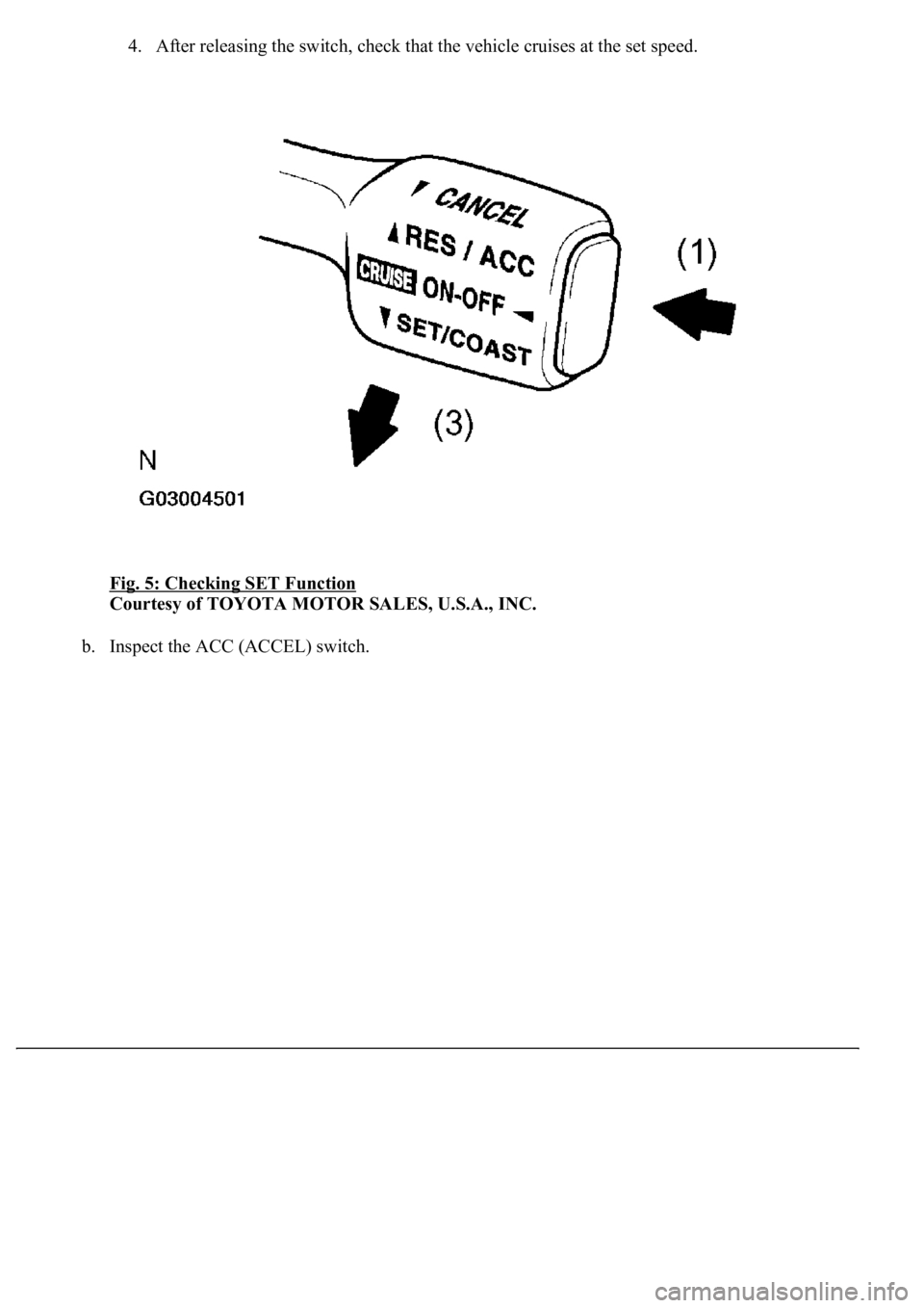
4. After releasing the switch, check that the vehicle cruises at the set speed.
Fig. 5: Checking SET Function
Courtesy of TOYOTA MOTOR SALES, U.S.A., INC.
b. Inspect the ACC (ACCEL) switch.
Page 1910 of 4500
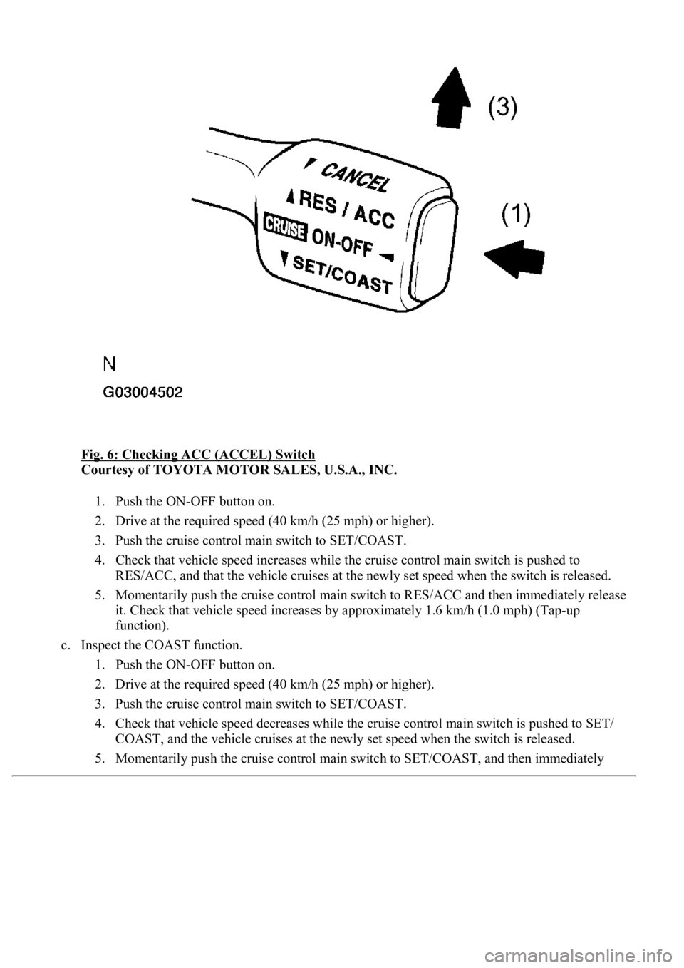
Fig. 6: Checking ACC (ACCEL) Switch
Courtesy of TOYOTA MOTOR SALES, U.S.A., INC.
1. Push the ON-OFF button on.
2. Drive at the required speed (40 km/h (25 mph) or higher).
3. Push the cruise control main switch to SET/COAST.
4. Check that vehicle speed increases while the cruise control main switch is pushed to
RES/ACC, and that the vehicle cruises at the newly set speed when the switch is released.
5. Momentarily push the cruise control main switch to RES/ACC and then immediately release
it. Check that vehicle speed increases by approximately 1.6 km/h (1.0 mph) (Tap-up
function).
c. Inspect the COAST function.
1. Push the ON-OFF button on.
2. Drive at the required speed (40 km/h (25 mph) or higher).
3. Push the cruise control main switch to SET/COAST.
4. Check that vehicle speed decreases while the cruise control main switch is pushed to SET/
COAST, and the vehicle cruises at the newly set speed when the switch is released.
5. Momentaril
y push the cruise control main switch to SET/COAST, and then immediately