LEXUS LS430 2003 Factory Repair Manual
Manufacturer: LEXUS, Model Year: 2003,
Model line: LS430,
Model: LEXUS LS430 2003
Pages: 4500, PDF Size: 87.45 MB
LEXUS LS430 2003 Factory Repair Manual
LS430 2003
LEXUS
LEXUS
https://www.carmanualsonline.info/img/36/57050/w960_57050-0.png
LEXUS LS430 2003 Factory Repair Manual
Trending: maintenance reset, instrument panel, actuator damper, AC Compressor control valve, coolant capacity, drain bolt, seats
Page 2111 of 4500
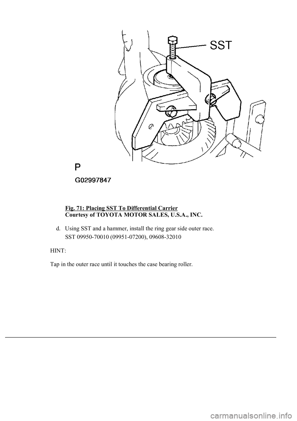
Fig. 71: Placing SST To Differential Carrier
Courtesy of TOYOTA MOTOR SALES, U.S.A., INC.
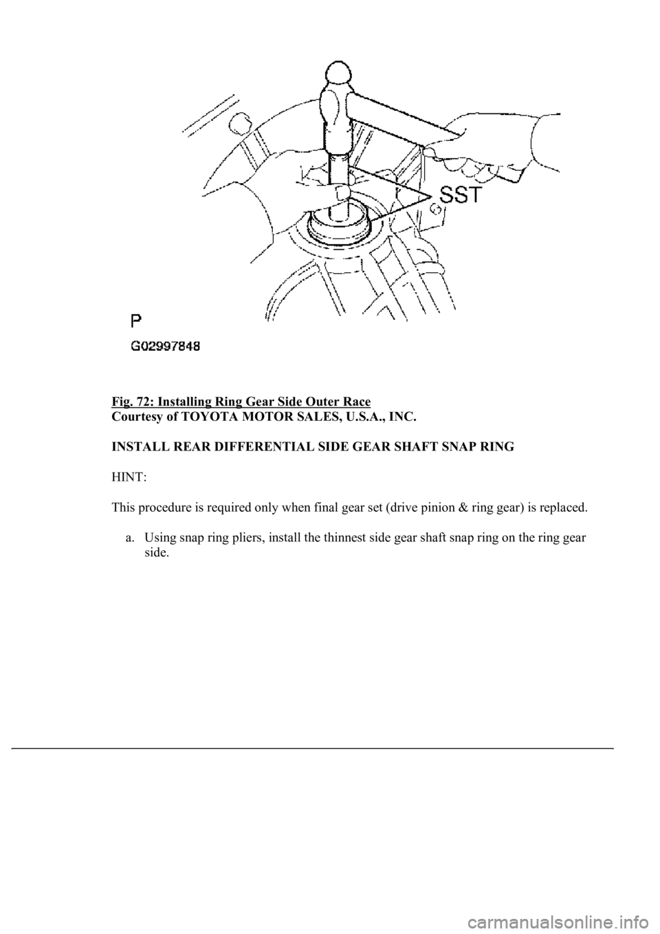
d. Using SST and a hammer, install the ring gear side outer race.
SST 09950-70010 (09951-07200), 09608-32010
HINT:
Tap in the outer race until it touches the case bearin
g roller.
Page 2112 of 4500
Fig. 72: Installing Ring Gear Side Outer Race
Courtesy of TOYOTA MOTOR SALES, U.S.A., INC.
INSTALL REAR DIFFERENTIAL SIDE GEAR SHAFT SNAP RING
HINT:
This procedure is required only when final gear set (drive pinion & ring gear) is replaced.
a. Using snap ring pliers, install the thinnest side gear shaft snap ring on the ring gear
side.
Page 2113 of 4500
Fig. 73: Installing Rear Differential Side Gear Shaft Snap Ring
Courtesy of TOYOTA MOTOR SALES, U.S.A., INC.
b. Install a dial indicator to the differential carrier.
c. Tighten the SST bolt to alter the differential carrier's shape by approximately 0.1 mm
(0.004 in.).
SST 09571-50010
HINT:
Set the dial indicator to the rearmost position (upper side in the illustration) of
the area around where the side gear shaft oil seal is tapped in.
Tighten the SST bolt to apply the preload to the case bearing.
d. Turn the rin
g gear clockwise and counterclockwise several times.
Page 2114 of 4500
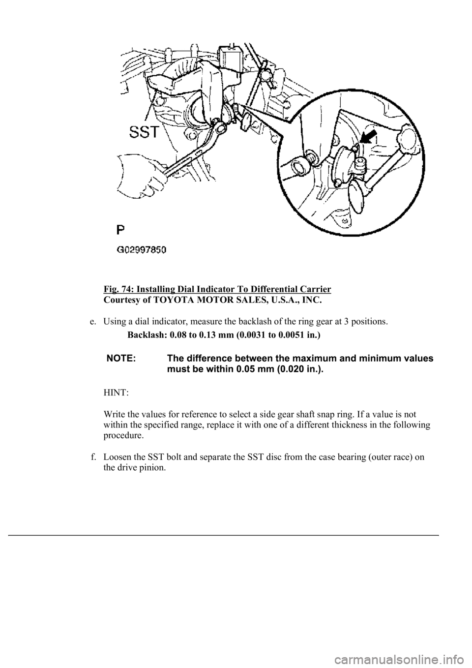
Fig. 74: Installing Dial Indicator To Differential Carrier
Courtesy of TOYOTA MOTOR SALES, U.S.A., INC.
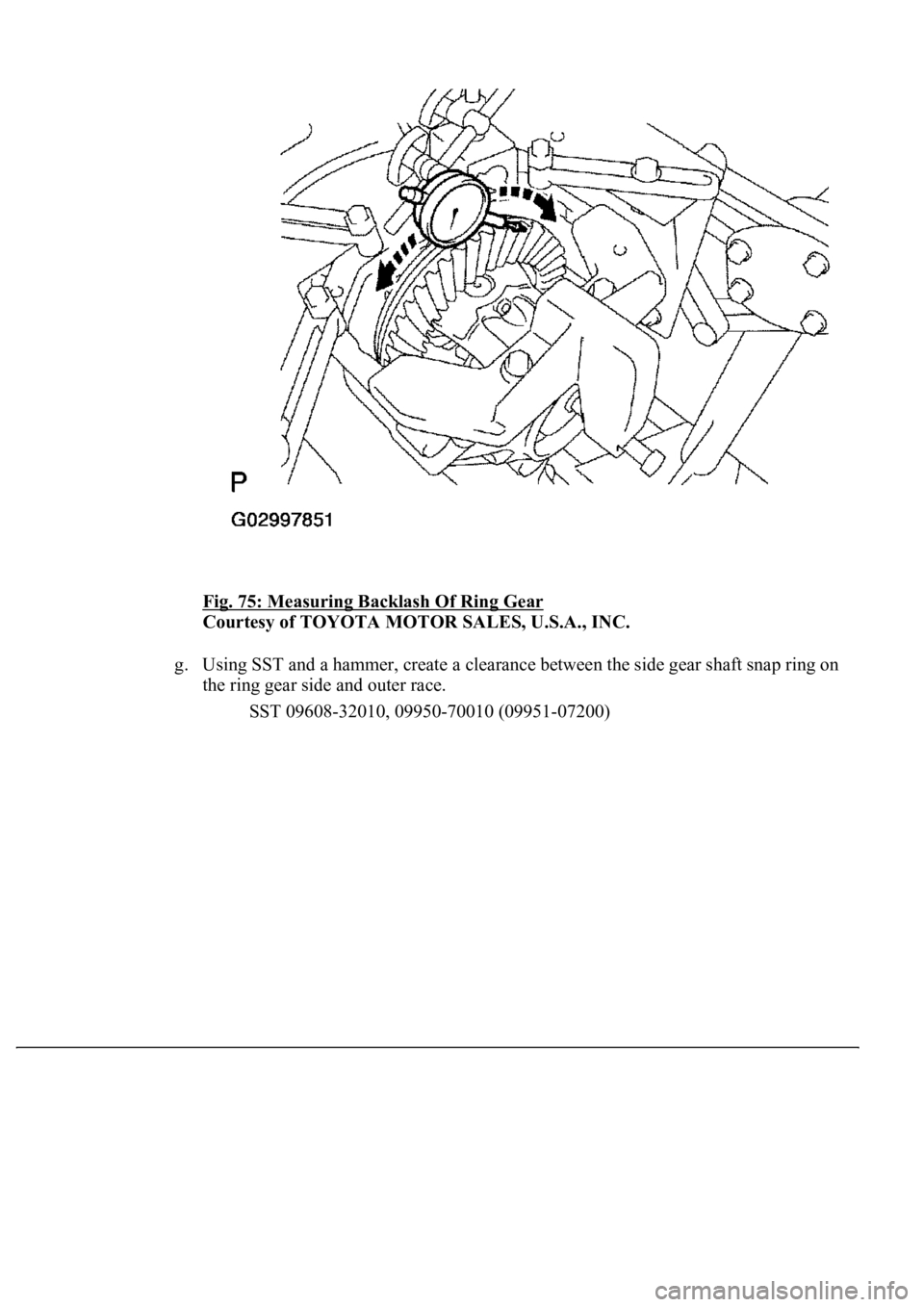
e. Using a dial indicator, measure the backlash of the ring gear at 3 positions.
Backlash: 0.08 to 0.13 mm (0.0031 to 0.0051 in.)
HINT:
Write the values for reference to select a side gear shaft snap ring. If a value is not
within the specified range, replace it with one of a different thickness in the following
procedure.
f. Loosen the SST bolt and separate the SST disc from the case bearing (outer race) on
the drive pinion.
Page 2115 of 4500
Fig. 75: Measuring Backlash Of Ring Gear
Courtesy of TOYOTA MOTOR SALES, U.S.A., INC.
g. Using SST and a hammer, create a clearance between the side gear shaft snap ring on
the ring gear side and outer race.
SST 09608-32010, 09950-70010 (09951-07200)
Page 2116 of 4500
Fig. 76: Creating Clearance Between Side Gear Shaft Snap Ring On Ring Gear
Side And Outer Race
Courtesy of TOYOTA MOTOR SALES, U.S.A., INC.
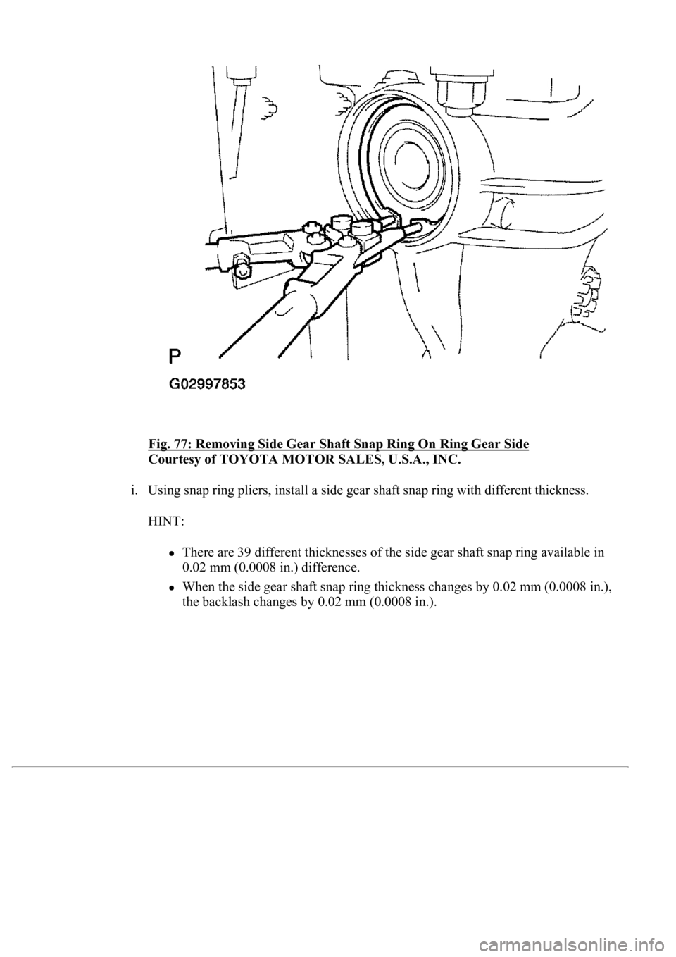
h. Usin
g snap ring pliers, remove the side gear shaft snap ring on the ring gear side.
Page 2117 of 4500
Fig. 77: Removing Side Gear Shaft Snap Ring On Ring Gear Side
Courtesy of TOYOTA MOTOR SALES, U.S.A., INC.
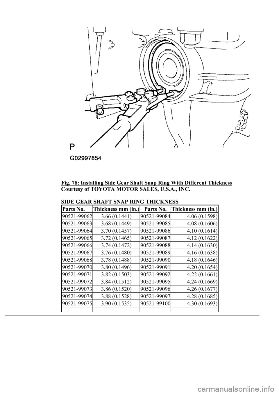
i. Using snap ring pliers, install a side gear shaft snap ring with different thickness.
HINT:
There are 39 different thicknesses of the side gear shaft snap ring available in
0.02 mm (0.0008 in.) difference.
<003a004b0048005100030057004b004800030056004c004700480003004a00480044005500030056004b0044004900570003005600510044005300030055004c0051004a00030057004b004c0046004e005100480056005600030046004b00440051004a00
48005600030045005c00030013001100130015000300500050[ (0.0008 in.),
the backlash chan
ges by 0.02 mm (0.0008 in.).
Page 2118 of 4500
Fig. 78: Installing Side Gear Shaft Snap Ring With Different Thickness
Courtesy of TOYOTA MOTOR SALES, U.S.A., INC.
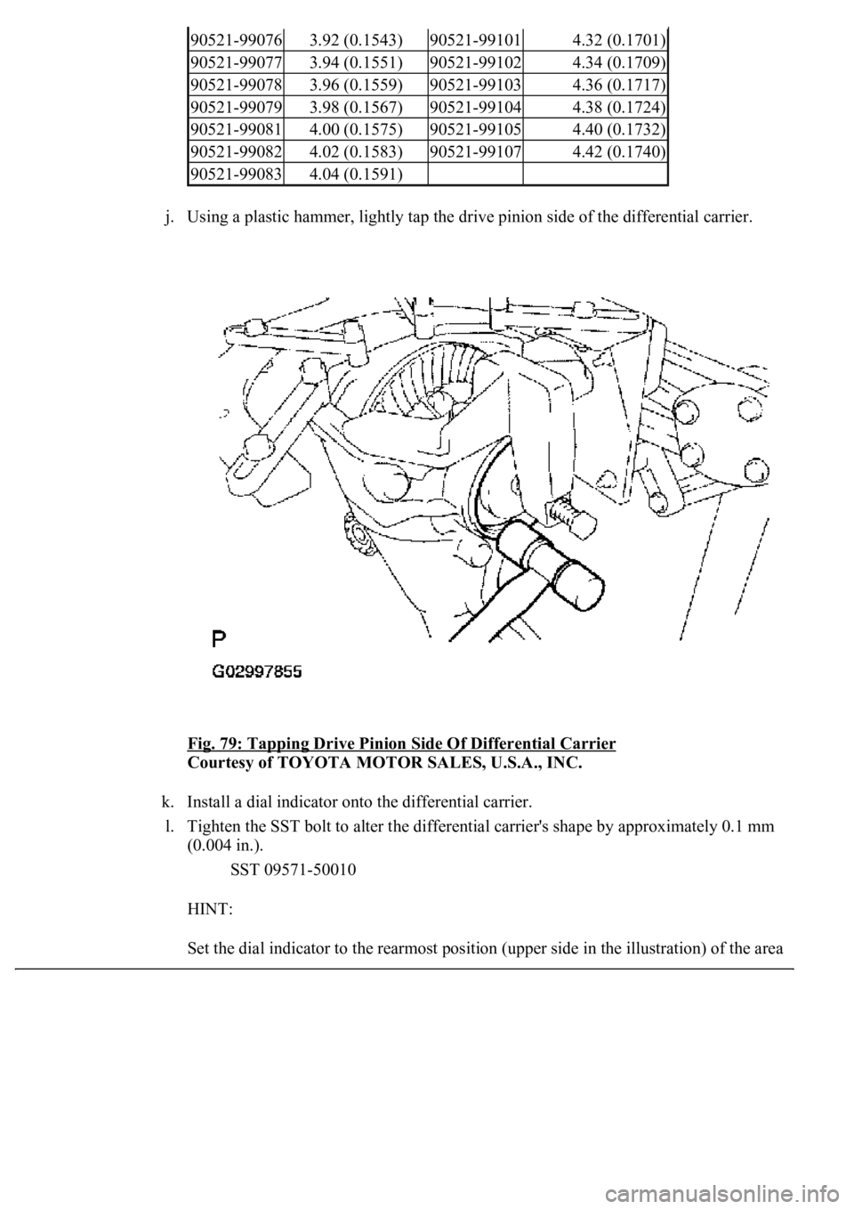
SIDE GEAR SHAFT SNAP RING THICKNESS
Parts No.Thickness mm (in.)Parts No.Thickness mm (in.)
90521-990623.66 (0.1441)90521-990844.06 (0.1598)
90521-990633.68 (0.1449)90521-990854.08 (0.1606)
90521-990643.70 (0.1457)90521-990864.10 (0.1614)
90521-990653.72 (0.1465)90521-990874.12 (0.1622)
90521-990663.74 (0.1472)90521-990884.14 (0.1630)
90521-990673.76 (0.1480)90521-990894.16 (0.1638)
90521-990683.78 (0.1488)90521-990904.18 (0.1646)
90521-990703.80 (0.1496)90521-990914.20 (0.1654)
90521-990713.82 (0.1503)90521-990924.22 (0.1661)
90521-990723.84 (0.1512)90521-990954.24 (0.1669)
90521-990733.86 (0.1520)90521-990964.26 (0.1677)
90521-990743.88 (0.1528)90521-990974.28 (0.1685)
90521-990753.90 (0.1535)90521-991004.30 (0.1693)
Page 2119 of 4500
j. Using a plastic hammer, lightly tap the drive pinion side of the differential carrier.
Fig. 79: Tapping Drive Pinion Side Of Differential Carrier
Courtesy of TOYOTA MOTOR SALES, U.S.A., INC.
k. Install a dial indicator onto the differential carrier.
l. Tighten the SST bolt to alter the differential carrier's shape by approximately 0.1 mm
(0.004 in.).
SST 09571-50010
HINT:
Set the dial indicator to the rearmost position (upper side in the illustration) of the area
90521-990763.92 (0.1543)90521-991014.32 (0.1701)
90521-990773.94 (0.1551)90521-991024.34 (0.1709)
90521-990783.96 (0.1559)90521-991034.36 (0.1717)
90521-990793.98 (0.1567)90521-991044.38 (0.1724)
90521-990814.00 (0.1575)90521-991054.40 (0.1732)
90521-990824.02 (0.1583)90521-991074.42 (0.1740)
90521-990834.04 (0.1591)
Page 2120 of 4500
around where the side oil seal tapped in.
Fig. 80: Installing Dial Indicator Onto Differential Carrier
Courtesy of TOYOTA MOTOR SALES, U.S.A., INC.
m. Using a dial indicator, measure the ring gear backlash.
Backlash: 0.08 to 0.13 mm (0.0031 to 0.0051 in.)
n. If the backlash is not within the specified range, replace the side gear shaft snap ring
on the rin
g gear side with one of a different thickness.
Trending: oil, B2799, evaporator, Compressor control valve, brake light, valve assy, engine
