LEXUS LS430 2003 Factory Repair Manual
Manufacturer: LEXUS, Model Year: 2003,
Model line: LS430,
Model: LEXUS LS430 2003
Pages: 4500, PDF Size: 87.45 MB
LEXUS LS430 2003 Factory Repair Manual
LS430 2003
LEXUS
LEXUS
https://www.carmanualsonline.info/img/36/57050/w960_57050-0.png
LEXUS LS430 2003 Factory Repair Manual
Trending: water pump, fog light, Soft hard, B2402, oil dipstick, remote start, oil
Page 2131 of 4500
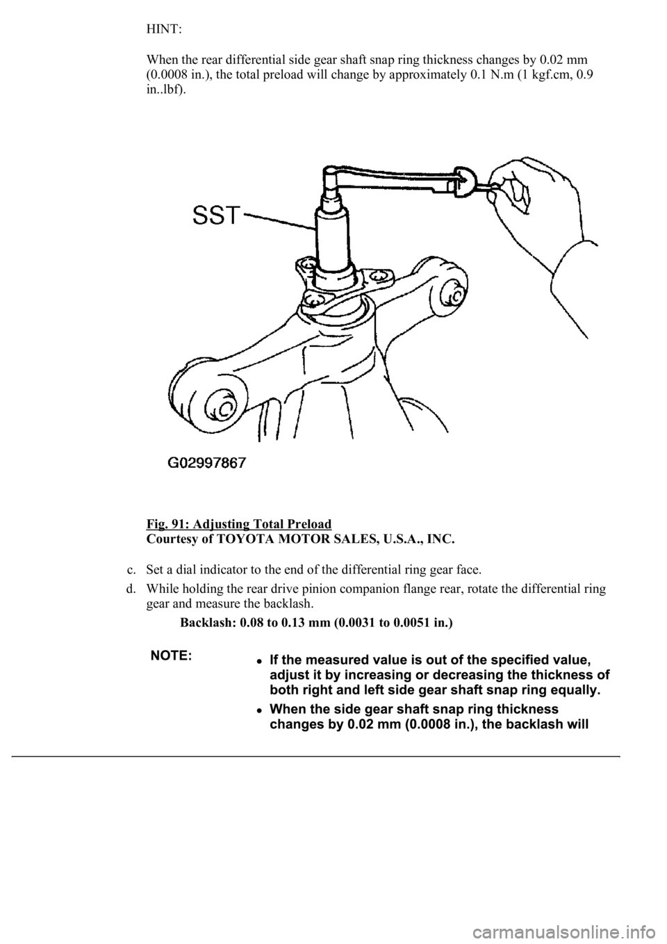
HINT:
When the rear differential side gear shaft snap ring thickness changes by 0.02 mm
(0.0008 in.), the total preload will change by approximately 0.1 N.m (1 kgf.cm, 0.9
in..lbf).
Fig. 91: Adjusting Total Preload
Courtesy of TOYOTA MOTOR SALES, U.S.A., INC.
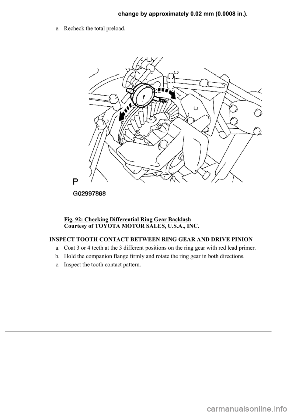
c. Set a dial indicator to the end of the differential ring gear face.
d. While holding the rear drive pinion companion flange rear, rotate the differential ring
gear and measure the backlash.
Backlash: 0.08 to 0.13 mm (0.0031 to 0.0051 in.)
Page 2132 of 4500
e. Recheck the total preload.
Fig. 92: Checking Differential Ring Gear Backlash
Courtesy of TOYOTA MOTOR SALES, U.S.A., INC.
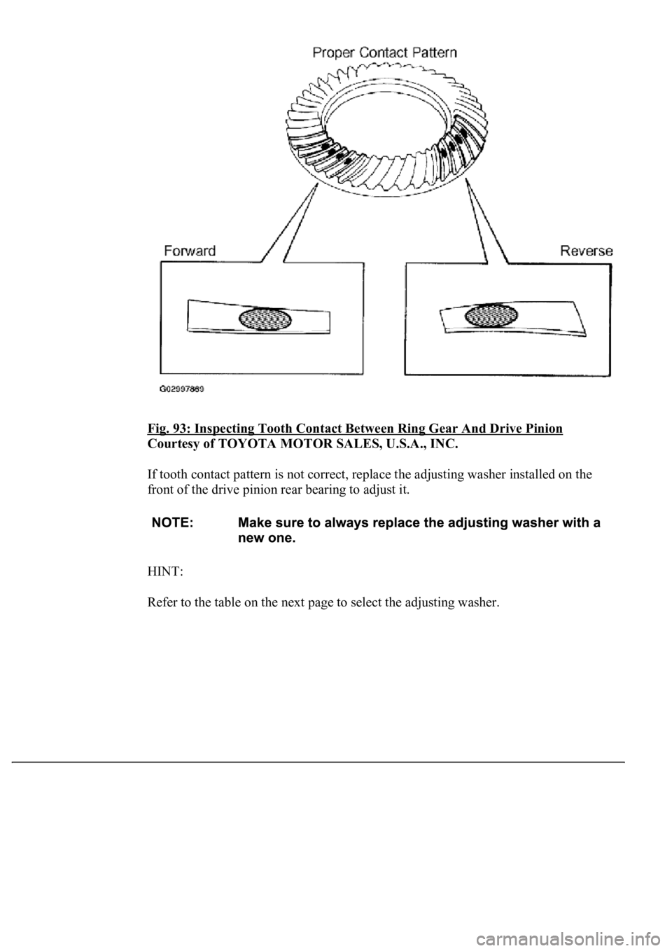
INSPECT TOOTH CONTACT BETWEEN RING GEAR AND DRIVE PINION
a. Coat 3 or 4 teeth at the 3 different positions on the ring gear with red lead primer.
b. Hold the companion flange firmly and rotate the ring gear in both directions.
c. Inspect the tooth contact pattern.
Page 2133 of 4500
Fig. 93: Inspecting Tooth Contact Between Ring Gear And Drive Pinion
Courtesy of TOYOTA MOTOR SALES, U.S.A., INC.
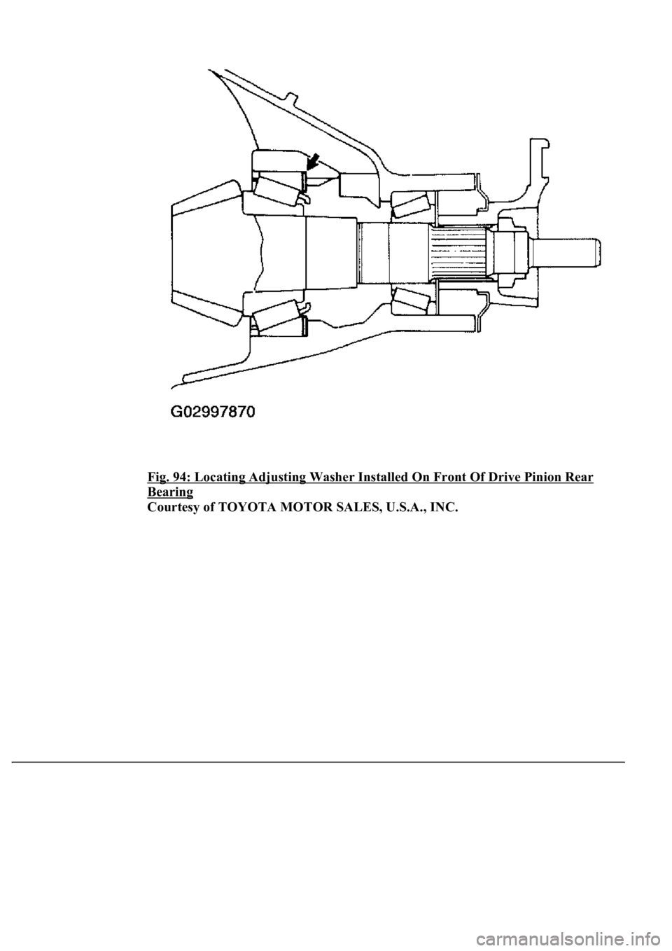
If tooth contact pattern is not correct, replace the adjusting washer installed on the
front of the drive pinion rear bearing to adjust it.
HINT:
Refer to the table on the next page to select the adjusting washer.
Page 2134 of 4500
Fig. 94: Locating Adjusting Washer Installed On Front Of Drive Pinion Rear
Bearing
Courtesy of TOYOTA MOTOR SALES, U.S.A., INC.
Page 2135 of 4500
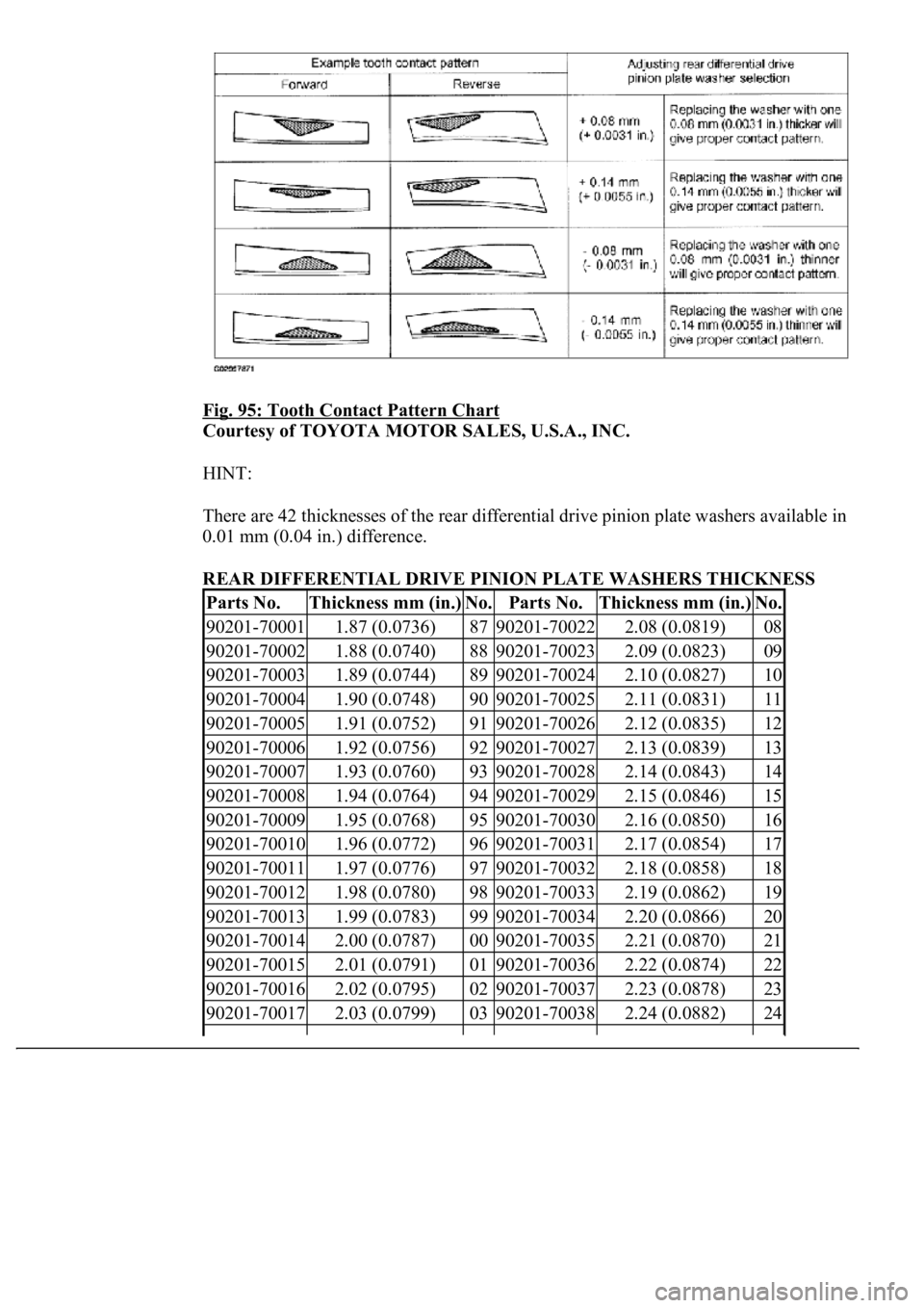
Fig. 95: Tooth Contact Pattern Chart
Courtesy of TOYOTA MOTOR SALES, U.S.A., INC.
HINT:
There are 42 thicknesses of the rear differential drive pinion plate washers available in
0.01 mm (0.04 in.) difference.
REAR DIFFERENTIAL DRIVE PINION PLATE WASHERS THICKNESS
Parts No.Thickness mm (in.)No.Parts No.Thickness mm (in.)No.
90201-700011.87 (0.0736)8790201-700222.08 (0.0819)08
90201-700021.88 (0.0740)8890201-700232.09 (0.0823)09
90201-700031.89 (0.0744)8990201-700242.10 (0.0827)10
90201-700041.90 (0.0748)9090201-700252.11 (0.0831)11
90201-700051.91 (0.0752)9190201-700262.12 (0.0835)12
90201-700061.92 (0.0756)9290201-700272.13 (0.0839)13
90201-700071.93 (0.0760)9390201-700282.14 (0.0843)14
90201-700081.94 (0.0764)9490201-700292.15 (0.0846)15
90201-700091.95 (0.0768)9590201-700302.16 (0.0850)16
90201-700101.96 (0.0772)9690201-700312.17 (0.0854)17
90201-700111.97 (0.0776)9790201-700322.18 (0.0858)18
90201-700121.98 (0.0780)9890201-700332.19 (0.0862)19
90201-700131.99 (0.0783)9990201-700342.20 (0.0866)20
90201-700142.00 (0.0787)0090201-700352.21 (0.0870)21
90201-700152.01 (0.0791)0190201-700362.22 (0.0874)22
90201-700162.02 (0.0795)0290201-700372.23 (0.0878)23
90201-700172.03 (0.0799)0390201-700382.24 (0.0882)24
Page 2136 of 4500
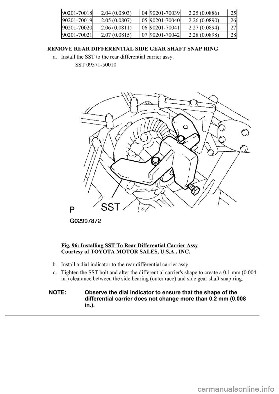
REMOVE REAR DIFFERENTIAL SIDE GEAR SHAFT SNAP RING
a. Install the SST to the rear differential carrier assy.
SST 09571-50010
Fig. 96: Installing SST To Rear Differential Carrier Assy
Courtesy of TOYOTA MOTOR SALES, U.S.A., INC.
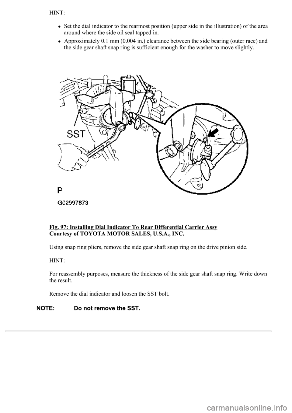
b. Install a dial indicator to the rear differential carrier assy.
c. Tighten the SST bolt and alter the differential carrier's shape to create a 0.1 mm (0.004
in.) clearance between the side bearing (outer race) and side gear shaft snap ring.
90201-700182.04 (0.0803)0490201-700392.25 (0.0886)25
90201-700192.05 (0.0807)0590201-700402.26 (0.0890)26
90201-700202.06 (0.0811)0690201-700412.27 (0.0894)27
90201-700212.07 (0.0815)0790201-700422.28 (0.0898)28
Page 2137 of 4500
HINT:
Set the dial indicator to the rearmost position (upper side in the illustration) of the area
around where the side oil seal tapped in.
Approximately 0.1 mm (0.004 in.) clearance between the side bearing (outer race) and
the side gear shaft snap ring is sufficient enough for the washer to move slightly.
Fig. 97: Installing Dial Indicator To Rear Differential Carrier Assy
Courtesy of TOYOTA MOTOR SALES, U.S.A., INC.
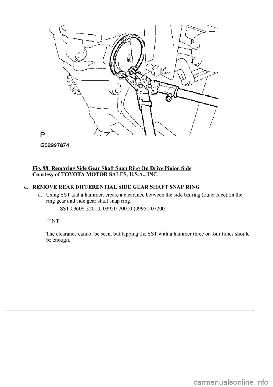
Using snap ring pliers, remove the side gear shaft snap ring on the drive pinion side.
HINT:
For reassembly purposes, measure the thickness of the side gear shaft snap ring. Write down
the result.
Remove the dial indicator and loosen the SST bolt.
Page 2138 of 4500
Fig. 98: Removing Side Gear Shaft Snap Ring On Drive Pinion Side
Courtesy of TOYOTA MOTOR SALES, U.S.A., INC.
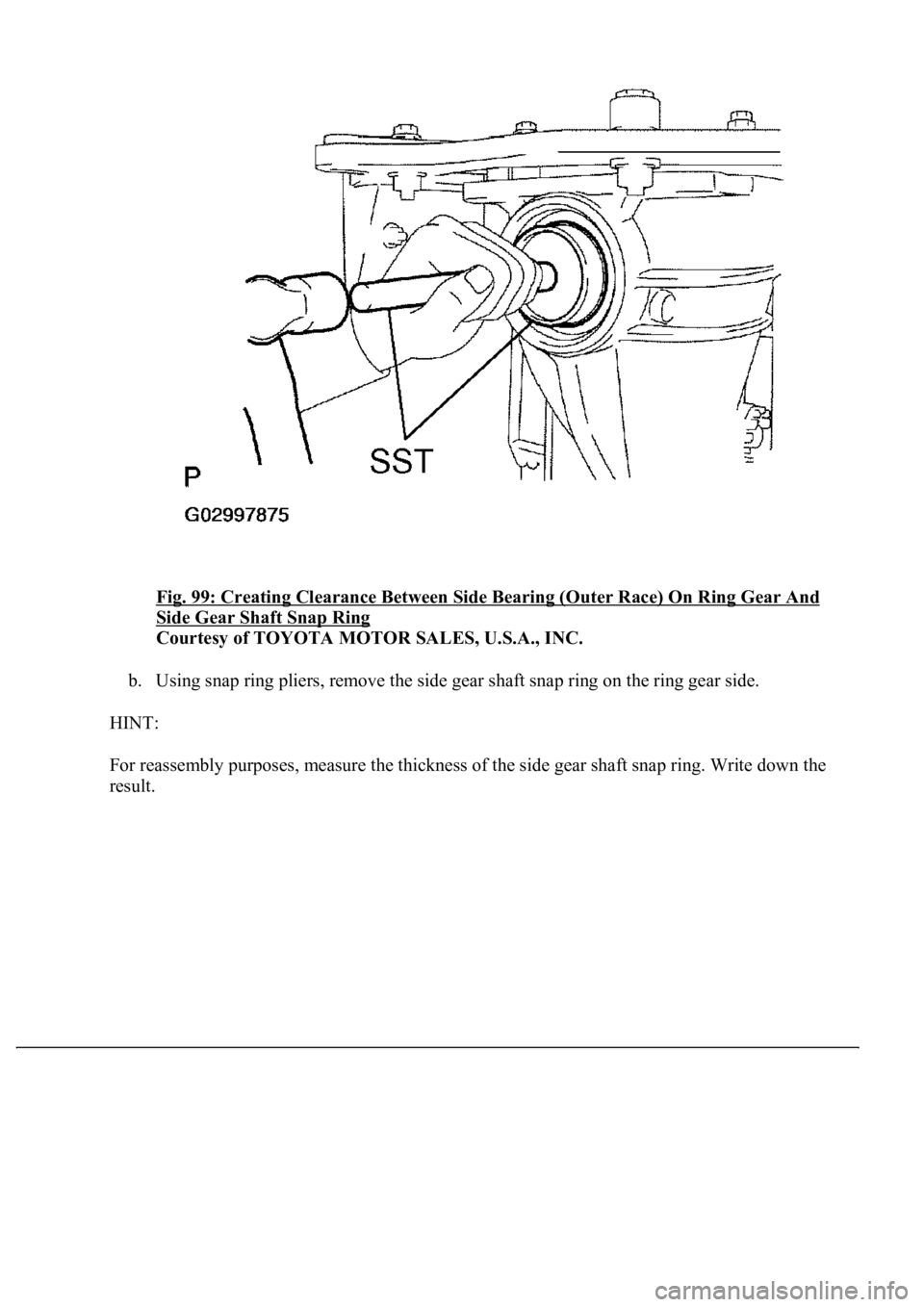
d.REMOVE REAR DIFFERENTIAL SIDE GEAR SHAFT SNAP RING
a. Using SST and a hammer, create a clearance between the side bearing (outer race) on the
ring gear and side gear shaft snap ring.
SST 09608-32010, 09950-70010 (09951-07200)
HINT:
The clearance cannot be seen, but tapping the SST with a hammer three or four times should
be enough.
Page 2139 of 4500
Fig. 99: Creating Clearance Between Side Bearing (Outer Race) On Ring Gear And
Side Gear Shaft Snap Ring
Courtesy of TOYOTA MOTOR SALES, U.S.A., INC.
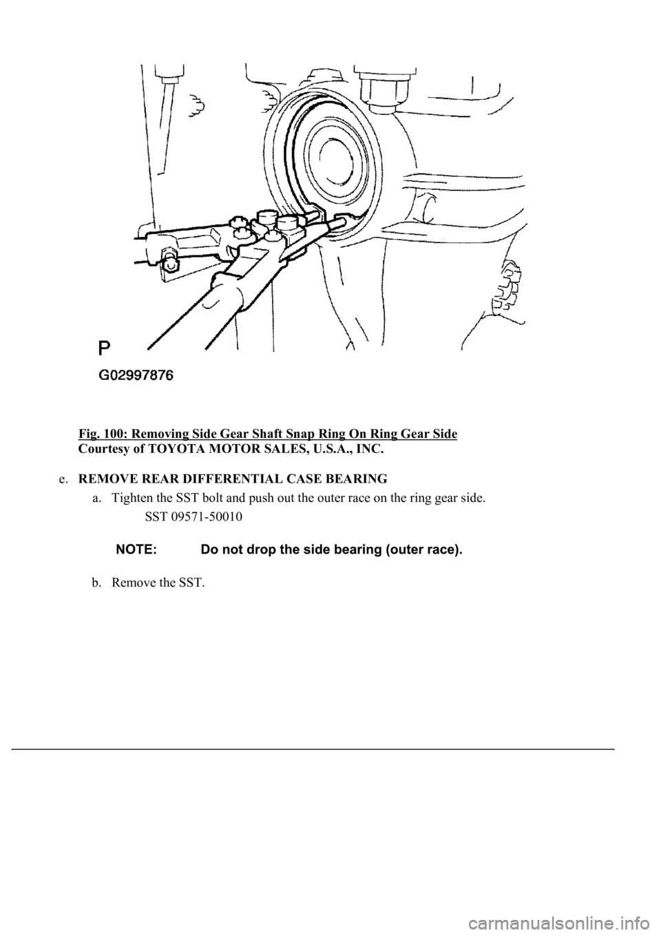
b. Using snap ring pliers, remove the side gear shaft snap ring on the ring gear side.
HINT:
For reassembly purposes, measure the thickness of the side gear shaft snap ring. Write down the
result.
Page 2140 of 4500
Fig. 100: Removing Side Gear Shaft Snap Ring On Ring Gear Side
Courtesy of TOYOTA MOTOR SALES, U.S.A., INC.
e.REMOVE REAR DIFFERENTIAL CASE BEARING
a. Tighten the SST bolt and push out the outer race on the ring gear side.
SST 09571-50010
b. Remove the SST.
Trending: Skid, Air Conditioning Compressor, wheel bolts, tire type, vacuum switch, Modulated, vacuum switching valve
