LEXUS LS430 2003 Factory Repair Manual
Manufacturer: LEXUS, Model Year: 2003,
Model line: LS430,
Model: LEXUS LS430 2003
Pages: 4500, PDF Size: 87.45 MB
LEXUS LS430 2003 Factory Repair Manual
LS430 2003
LEXUS
LEXUS
https://www.carmanualsonline.info/img/36/57050/w960_57050-0.png
LEXUS LS430 2003 Factory Repair Manual
Trending: fuel filter location, maintenance reset, ESP, diagnostic menu, rear seat back assembly, dlc3, Combination
Page 2171 of 4500
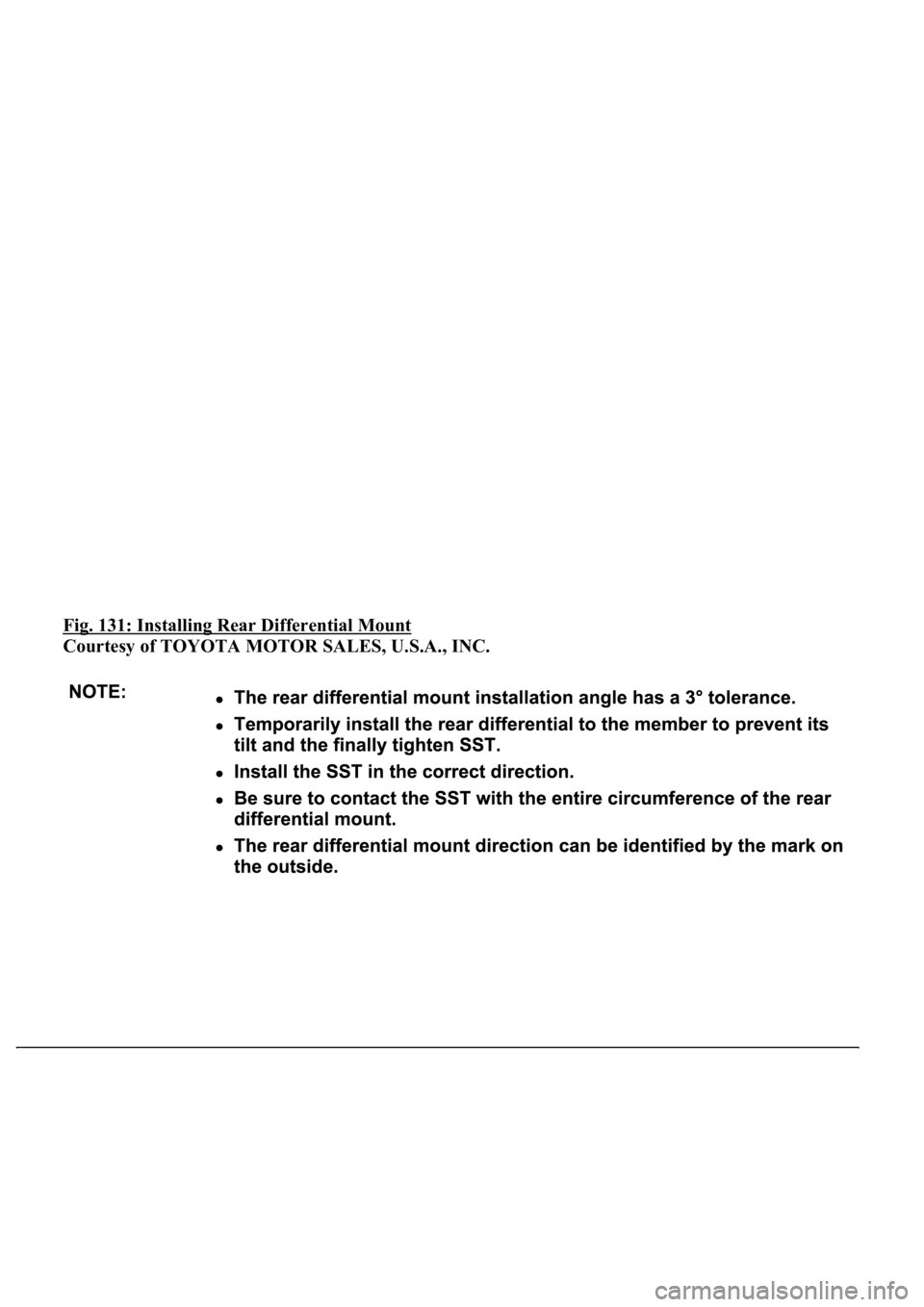
Fig. 131: Installing Rear Differential Mount
Courtesy of TOYOTA MOTOR SALES, U.S.A., INC.
Page 2172 of 4500
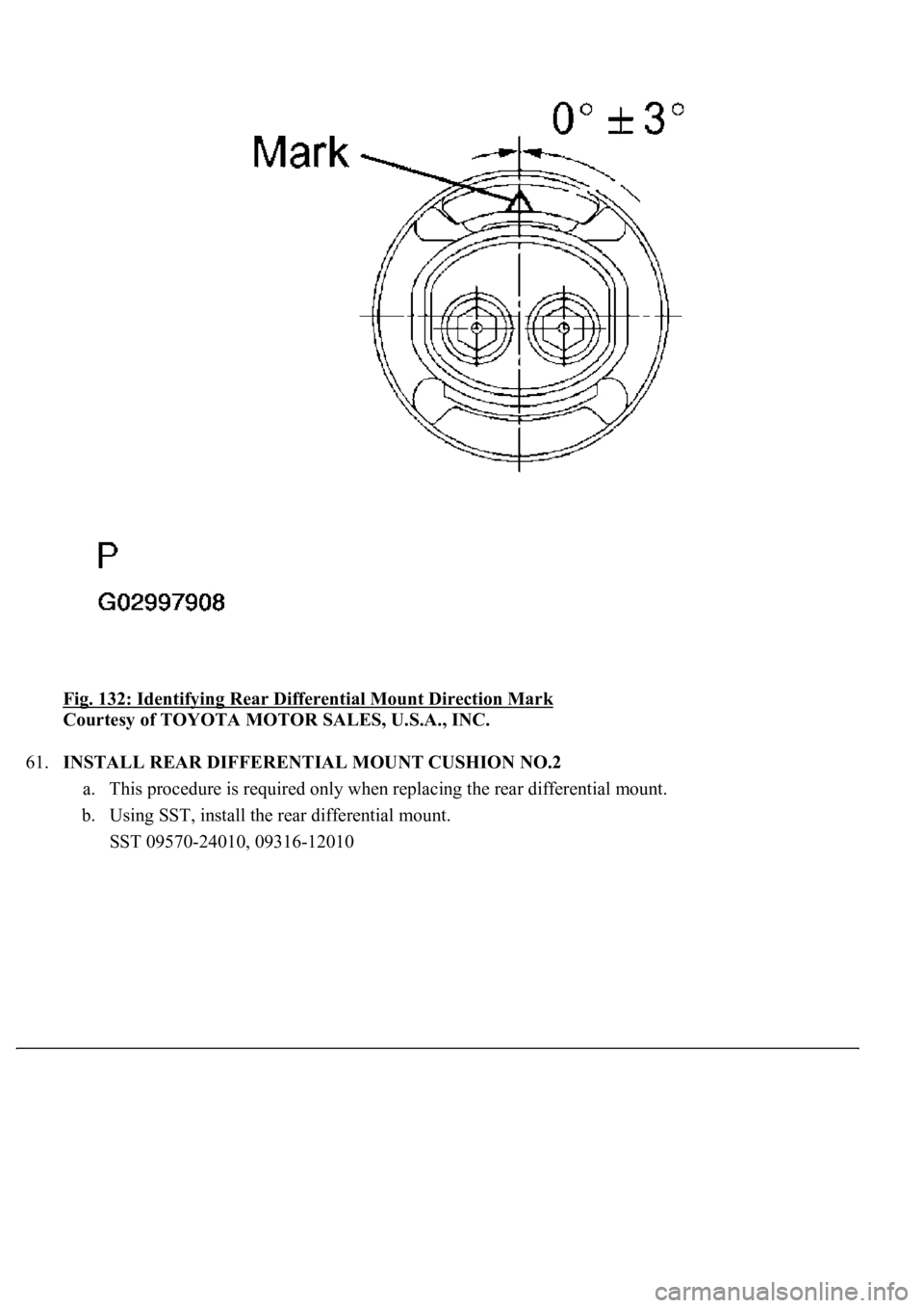
Fig. 132: Identifying Rear Differential Mount Direction Mark
Courtesy of TOYOTA MOTOR SALES, U.S.A., INC.
61.INSTALL REAR DIFFERENTIAL MOUNT CUSHION NO.2
a. This procedure is required only when replacing the rear differential mount.
b. Using SST, install the rear differential mount.
SST 09570-24010, 09316-12010
Page 2173 of 4500
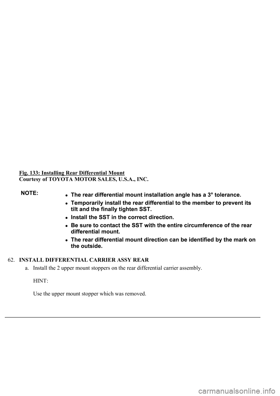
Fig. 133: Installing Rear Differential Mount
Courtesy of TOYOTA MOTOR SALES, U.S.A., INC.
62.INSTALL DIFFERENTIAL CARRIER ASSY REAR
a. Install the 2 upper mount stoppers on the rear differential carrier assembly.
HINT:
Use the upper mount stopper which was removed.
Page 2174 of 4500
Fig. 134: Identifying Rear Differential Mount Direction Mark
Courtesy of TOYOTA MOTOR SALES, U.S.A., INC.
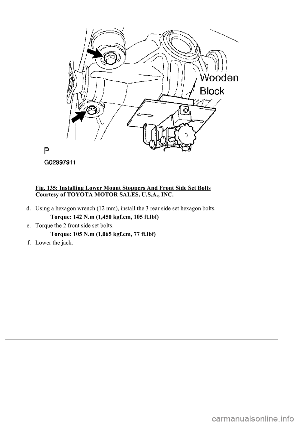
b. Support the rear differential carrier assembly with a jack and wooden block.
c. Temporally install the lower mount stoppers and 2 new front side set bolts.
Page 2175 of 4500
Fig. 135: Installing Lower Mount Stoppers And Front Side Set Bolts
Courtesy of TOYOTA MOTOR SALES, U.S.A., INC.
d. Using a hexagon wrench (12 mm), install the 3 rear side set hexagon bolts.
Torque: 142 N.m (1,450 kgf.cm, 105 ft.lbf)
e. Torque the 2 front side set bolts.
Torque: 105 N.m (1,065 kgf.cm, 77 ft.lbf)
f. Lower the
jack.
Page 2176 of 4500
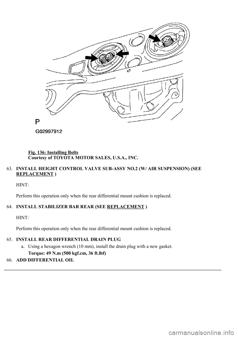
Fig. 136: Installing Bolts
Courtesy of TOYOTA MOTOR SALES, U.S.A., INC.
63.INSTALL HEIGHT CONTROL VALVE SUB-ASSY NO.2 (W/ AIR SUSPENSION) (SEE
REPLACEMENT
)
HINT:
Perform this operation only when the rear differential mount cushion is replaced.
64.INSTALL STABILIZER BAR REAR (SEE REPLACEMENT
)
HINT:
Perform this operation only when the rear differential mount cushion is replaced.
65.INSTALL REAR DIFFERENTIAL DRAIN PLUG
a. Using a hexagon wrench (10 mm), install the drain plug with a new gasket.
Torque: 49 N.m (500 kgf.cm, 36 ft.lbf)
66.ADD DIFFERENTIAL OIL
Page 2177 of 4500
a. Fill the rear differential carrier assy with differential gear oil equivalent.
Oil type: Differential synthetic gear oil GL-5 75W-90 or equivalent
Capacity: 1.35 +/- 0.05 liters (1.43 +/- 0.05 US qts, 1.19 +/- 0.04 Imp. qts)
67.INSPECT DIFFERENTIAL OIL (SEE ADJUSTMENT
)
68.INSTALL REAR DIFFERENTIAL FILLER PLUG
a. Using a hexagon wrench (10 mm), install the filler plug with a new gasket.
Torque: 49 N.m (500 kgf.cm, 36 ft.lbf)
69.INSTALL REAR DRIVE SHAFT ASSY LH (SEE REPLACEMENT
)
70.INSTALL REAR DRIVE SHAFT ASSY RH
HINT:
Installation procedure of the RH side is the same as that of the LH side.
71.INSTALL FRONT FLOOR HEAT INSULATOR NO.1
a. Install the front floor heat insulator No.1 with the 4 bolts.
Torque: 5.4 N.m (55 kgf.cm, 48 in..lbf)
72.INSTALL REAR WHEEL
a. Install the rear wheel with the 5 nuts.
Torque: 103 N.m (1,050 kgf.cm, 76 ft.lbf)
73. Install the ornament with the 10 bolts.
Torque: 20 N.m (204 kgf.cm, 15 ft.lbf)
74.INSTALL PROPELLER W/CENTER BEARING SHAFT ASSY (SEE OVERHAUL
)
75.FULLY TIGHTEN CENTER SUPPORT BEARING ASSY NO.1 (SEE OVERHAUL
)
SST 09922-10010
76.INSPECT AND ADJUST NO.2 AND NO.3 JOINT ANGLE (SEE OVERHAUL
)
77.INSTALL PROPELLER SHAFT HEAT INSULATOR (SEE OVERHAUL
)
78.INSTALL EXHAUST PIPE ASSY (SEE REPLACEMENT
)
79.INSTALL OXYGEN SENSOR (SEE REPLACEMENT
)
80.INSPECT AND ADJUST REAR WHEEL ALIGNMENT (SEE ADJUSTMENT
)
81.ADJUST VEHICLE HEIGHT (W/ AIR SUSPENSION) (SEE ON
-VEHICLE INSPECTION )
82.INSPECT HEADLIGHT AIM ONLY (SEE ADJUSTMENT
)
83.CHECK ABS SPEED SENSOR SIGNAL (SEE TEST MODE PROCEDURE
)
84.INSPECT AIR LEAK (W/ AIR SUSPENSION) (SEE REPLACEMENT
)
HINT:
Perform this operation onl
y when the rear differential mount cushion is replaced.
Page 2178 of 4500
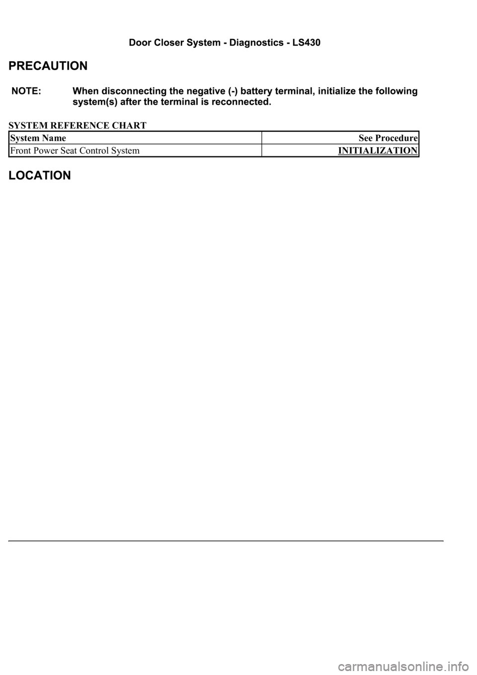
SYSTEM REFERENCE CHART
System NameSee Procedure
Front Power Seat Control SystemINITIALIZATION
Page 2179 of 4500
Fig. 1: Identifying Door Closer System Components Location
Courtesy of TOYOTA MOTOR SALES, U.S.A., INC.
Page 2180 of 4500
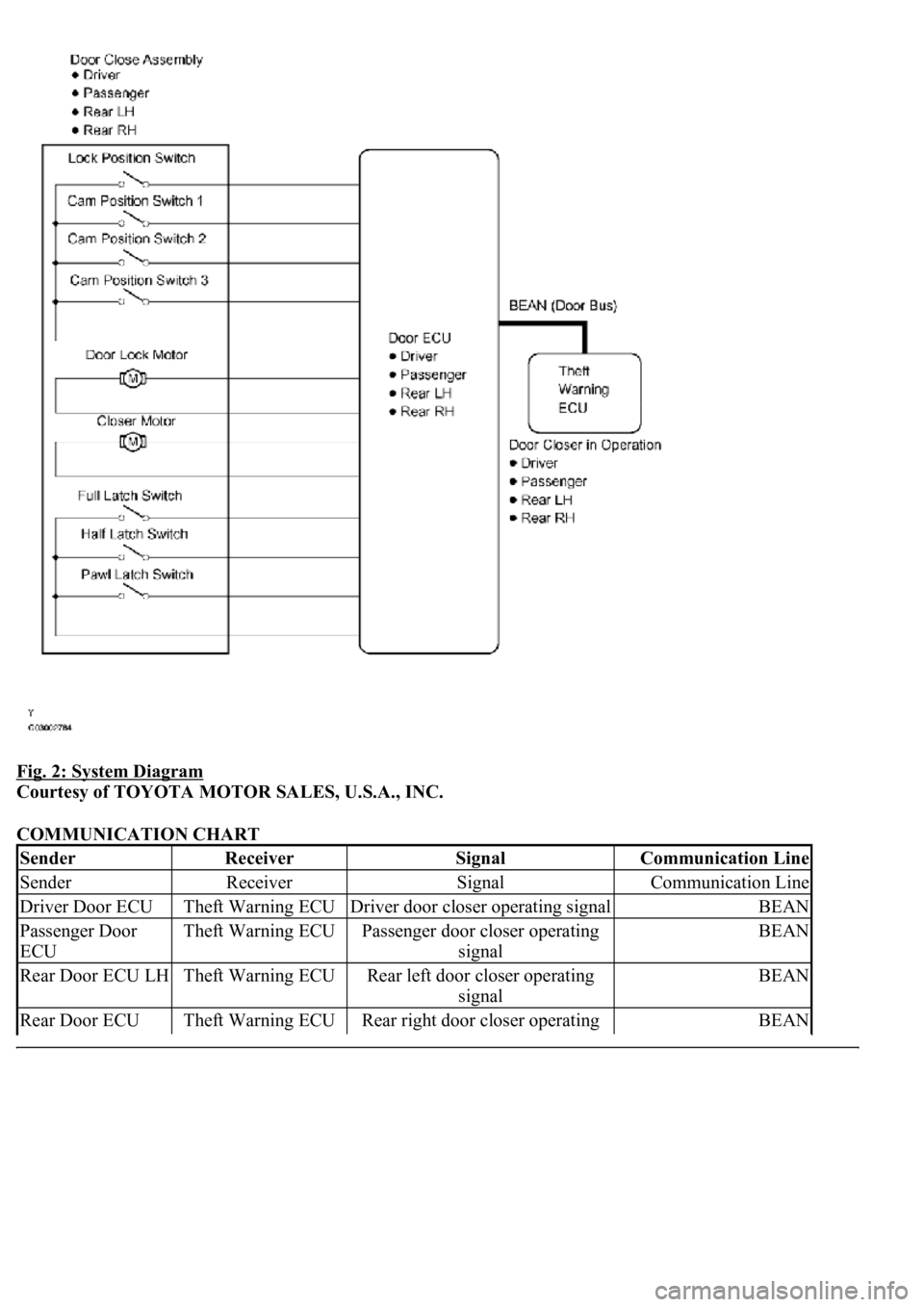
Fig. 2: System Diagram
Courtesy of TOYOTA MOTOR SALES, U.S.A., INC.
COMMUNICATION CHART
SenderReceiverSignalCommunication Line
SenderReceiverSignalCommunication Line
Driver Door ECUTheft Warning ECUDriver door closer operating signalBEAN
Passenger Door
ECUTheft Warning ECUPassenger door closer operating
signalBEAN
Rear Door ECU LHTheft Warning ECURear left door closer operating
signalBEAN
Rear Door ECU Theft Warning ECURear right door closer operating BEAN
Trending: Spark plug, oxygen sensor, hood release, key battery, change time, navigation system, fuel consumption
