LEXUS LS430 2003 Factory Repair Manual
Manufacturer: LEXUS, Model Year: 2003, Model line: LS430, Model: LEXUS LS430 2003Pages: 4500, PDF Size: 87.45 MB
Page 2671 of 4500
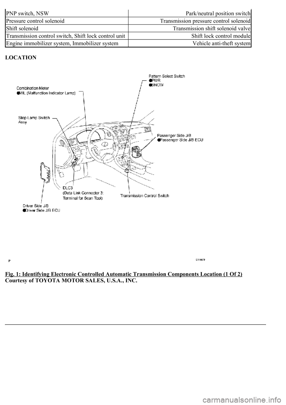
LOCATION
Fig. 1: Identifying Electronic Controlled Automatic Transmission Components Location (1 Of 2)
Courtesy of TOYOTA MOTOR SALES, U.S.A., INC.
PNP switch, NSWPark/neutral position switch
Pressure control solenoidTransmission pressure control solenoid
Shift solenoidTransmission shift solenoid valve
Transmission control switch, Shift lock control unitShift lock control module
Engine immobilizer system, Immobilizer systemVehicle anti-theft system
Page 2672 of 4500
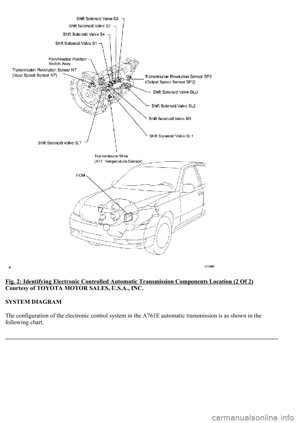
Fig. 2: Identifying Electronic Controlled Automatic Transmission Components Location (2 Of 2)
Courtesy of TOYOTA MOTOR SALES, U.S.A., INC.
SYSTEM DIAGRAM
The configuration of the electronic control system in the A761E automatic transmission is as shown in the
following chart.
Page 2673 of 4500
Fig. 3: Electronic Controlled Automatic Transmission System Diagram (1 Of 2)
Courtesy of TOYOTA MOTOR SALES, U.S.A., INC.
Page 2674 of 4500
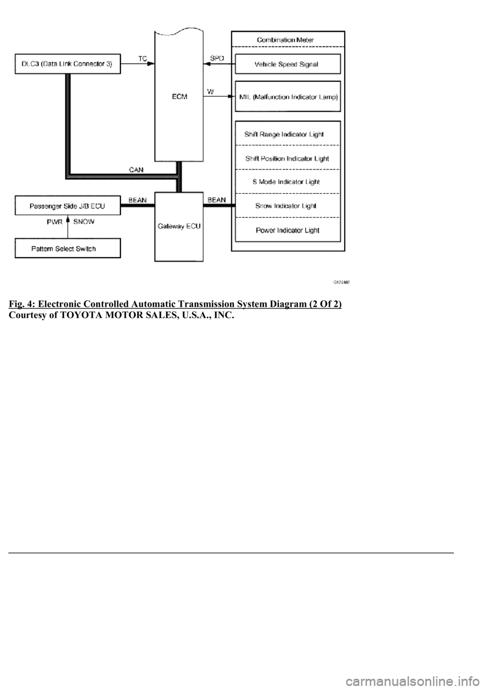
Fig. 4: Electronic Controlled Automatic Transmission System Diagram (2 Of 2)
Courtesy of TOYOTA MOTOR SALES, U.S.A., INC.
Page 2675 of 4500
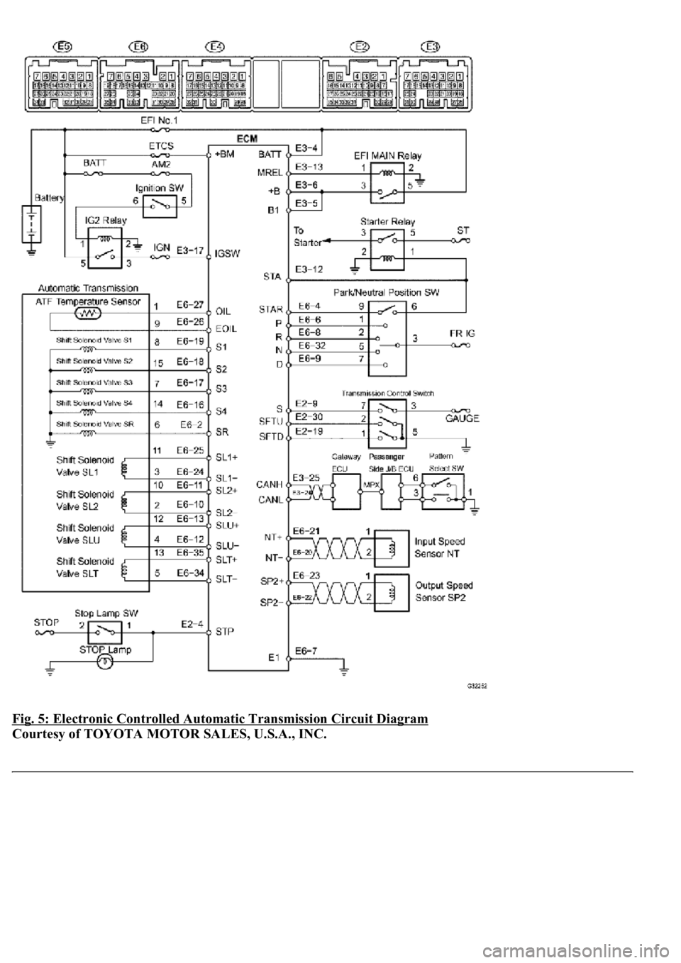
Fig. 5: Electronic Controlled Automatic Transmission Circuit Diagram
Courtesy of TOYOTA MOTOR SALES, U.S.A., INC.
Page 2676 of 4500
SYSTEM DESCRIPTION
1.SYSTEM DESCRIPTION
a. The ECT (Electronic controlled automatic transmission) is an automatic transmission that
electronically controls shift timing using the ECM. The ECM detects electrical signals that indicate
engine and driving conditions, and controls the shift point, based on driver habits and road
conditions. As a result, fuel efficiency and power transmission performance are improved.
<0036004b004c0049005700030056004b00520046004e0003004b00440056000300450048004800510003005500480047005800460048004700030045005c0003004600520051005700550052004f004f004c0051004a00030057004b004800030048005100
4a004c00510048000300440051004700030057005500440051[smission simultaneously. In
addition, the ECT has features such as follows:
Diagnostic function.
Fail-safe function when a malfunction occurs.
HOW TO PROCEED WITH TROUBLESHOOTING
HINT:
The ECM of this system is connected to the CAN and multiplex communication system. Therefore,
before starting troubleshooting, make sure to check that there is no trouble in the CAN and multiplex
communication system.
<0037004b00480003004b0044005100470010004b0048004f0047000300570048005600570048005500030046004400510003004500480003005800560048004700030044005700030056005700480053005600030016000f00030017000f00030019000f00
030044005100470003001c00110003[
1.Vehicle Brought to Workshop
2.Customer Problem Analysis (See CUSTOMER PROBLEM ANALYSIS CHECK
)
3.Connect the OBD II scan tool or hand-held tester to DLC3
4.Check and Clear DTCs and Freeze Frame Data (See DTC CHECK/CLEAR
)
5.Visual Inspection
6.Setting the Check Mode Diagnosis (See CHECK MODE PROCEDURE
)
7.Problem Symptom Confirmation (See ROAD TEST
)
Symptom does not occur: Go to step 8
Symptom occurs: Go to step 9
8.Symptom Simulation (See HOW TO PROCEED WITH TROUBLESHOOTING
)
9.DTC Check (See DTC CHECK/CLEAR
)
DTC is not output: Go to step 10
DTC is output: Go to step 17
10.Basic Inspection (See ADJUSTMENT
- AUTOMATIC TRANSMISSION FLUID ,
ADJUSTMENT
- PARK/NEUTRAL POSITION SWITCH ASSY and ADJUSTMENT -
FLOOR SHIFT ASSY
)
Page 2677 of 4500
NG: Go to step 19
OK: Go to next step
11.Mechanical System Test (See MECHANICAL SYSTEM TESTS
)
NG: Go to step 16
OK: Go to next step
12.Hydraulic Test (See HYDRAULIC TEST
)
NG: Go to step 16
OK: Go to next step
13.Manual Shifting Test (See MANUAL SHIFTING TEST
)
NG: Go to step 15
OK: Go to next step
14.Problem Symptoms Table Chapter 1 (See PROBLEM SYMPTOMS TABLE
)
NG: Go to step 18
OK: Go to next step
15.Problem Symptoms Table Chapter 2 (See PROBLEM SYMPTOMS TABLE
)
16.Part Inspection
Go to step 19
17.DTC Chart (See DIAGNOSTIC TROUBLE CODE CHART
)
18.Circuit Inspection
19.Repair or Replace
20.Confirmation Test
End
CUSTOMER PROBLEM ANALYSIS CHECK
Page 2678 of 4500
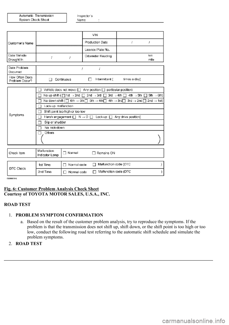
Fig. 6: Customer Problem Analysis Check Sheet
Courtesy of TOYOTA MOTOR SALES, U.S.A., INC.
ROAD TEST
1.PROBLEM SYMPTOM CONFIRMATION
a. Based on the result of the customer problem analysis, try to reproduce the symptoms. If the
problem is that the transmission does not shift up, shift down, or the shift point is too high or too
low, conduct the following road test referring to the automatic shift schedule and simulate the
problem symptoms.
2.ROAD TEST
Page 2679 of 4500
a. D position test:
Shift into the D position and fully depress the accelerator pedal and check the following points.
1. Check up-shift operation.
Check that 1 --> 2,2 --> 3,3 --> 4,4 --> 5 and 5 --> 6th up-shifts take place, and that the shift
points conform to the automatic shift schedule (see SERVICE DATA
).
HINT:
6th and 5th Gear Up-shift Prohibition Control
Engine coolant temperature is 55 °C (131 °F) or less and vehicle speed is at 51 km/h
(32 mph) or less. 4th Gear Up-shift Prohibition Control
Engine coolant temperature is 47 °C (117 °F) or less and vehicle speed is at 49 km/h
(30 mph) or less. Lock-up Prohibition Control
Brake pedal is depressed.
Accelerator pedal is released.
<00280051004a004c005100480003004600520052004f0044005100570003005700480050005300480055004400570058005500480003004c00560003001900130003008300260003000b001400170013000300830029000c0003005200550003004f004800
560056001100030003[
2. Check for shift shock and slip.
Check for shock and slip at the 1 --> 2,2 --> 3, 3 --> 4, 4 --> 5 and 5 --> 6th up-shifts.
3. Check for abnormal noise and vibration.
Check for abnormal noise and vibration when up-shifting from 1 --> 2, 2 --> 3, 3 --> 4, 4 -->
5 and 5 --> 6 while driving with the shift lever in the D position, and also check while driving
in the lock-up condition.
HINT:
The check for the cause of abnormal noise and vibration must be done thoroughly as it could
also be due to loss of balance in the differential, torque converter clutch, etc.
4. Check kick-down operation.
<0026004b00480046004e000300590048004b004c0046004f004800030056005300480048004700560003005a004b0048005100030057004b004800030015005100470003005700520003001400560057000f00030016005500470003005700520003001500
510047000f000300170057004b000300570052000300160055[d, 5th to 4th, and 6th to 5th
kick-downs take place while driving with the shift lever in the D position. Confirm that each
speed is within the applicable vehicle speed range indicated in the automatic shift schedule
(see SERVICE DATA
).
5. Check for abnormal shock and slip at kic
k-down.
Page 2680 of 4500
6. Check the lock-up mechanism.
Drive in the D position (4th, 5th or 6th gear), at a steady speed (lock-up ON).
Lightly depress the accelerator pedal and check that the engine speed does not change
abruptly.
HINT:
There is no lock-up function in the 1st, 2nd and 3rd gears.
If there is a big jump in engine speed, there is no lock-up.
b. S position test
Shift to the S position, depress the accelerator pedal and check the following points:
1. Check shift operation.
While driving in the D position and 6th gear, shift into the S position and back to the D
position. Check that the gear change 6 --> 5 down-shift and 5 --> 6 up-shift can be
performed.
With the shift lever in the S position (while the vehicle is stopped), shift into the "+"
position to check that the shift position on the combination meter changes as follows: 1
--> 2, 2 --> 3, 3 --> 4, 4 --> 5 and 5 --> 6.
While driving in the 5(S) position and 4th gear (at a vehicle speed of approximately 55
to 65 km/h (34 to 40 mph)), shift into the "-" position and check if the 4th gear down-
shift occurs and the engine brake performs properly.
While driving in the 4(S) position and 4th gear (at a vehicle speed of approximately 30
to 40 km/h (19 to 25 mph)), shift into the "-" position and check if the 3rd gear down-
shift occurs and the engine brake performs properly.
While driving in the 3(S) position and 3rd gear (at a vehicle speed of approximately 20
to 30 km/h (12 to 19 mph)), shift into the "-" position and check if the 2nd gear down-
shift occurs and the engine brake performs properly.
<003a004b004c004f0048000300470055004c0059004c0051004a0003004c005100030057004b004800030015000b0036000c0003005300520056004c0057004c00520051000300440051004700030015005100470003004a0048004400550003000b004400
5700030044000300590048004b004c0046004f004800030056[peed of approximately 10
to 20 km/h (6 to 12 mph)), shift into the "-" position and check if the 1st gear down-
shift occurs and the engine brake performs properly.
HINT:
Manual shift (S position) is prohibited under either of the following conditions:
Down-shifting may cause engine overrun.
The driver continuously down-shifts. (Down-shifting to 1st gear may not be performed.)
c. R position test:
Shift into the R position, lightly depress the accelerator pedal, and check that the vehicle moves
backward without any abnormal noise or vibration.