LEXUS LS430 2003 Factory Repair Manual
Manufacturer: LEXUS, Model Year: 2003,
Model line: LS430,
Model: LEXUS LS430 2003
Pages: 4500, PDF Size: 87.45 MB
LEXUS LS430 2003 Factory Repair Manual
LS430 2003
LEXUS
LEXUS
https://www.carmanualsonline.info/img/36/57050/w960_57050-0.png
LEXUS LS430 2003 Factory Repair Manual
Trending: alarm, charging, CD player, washer fluid, air conditioning, B2620, service interval
Page 2901 of 4500
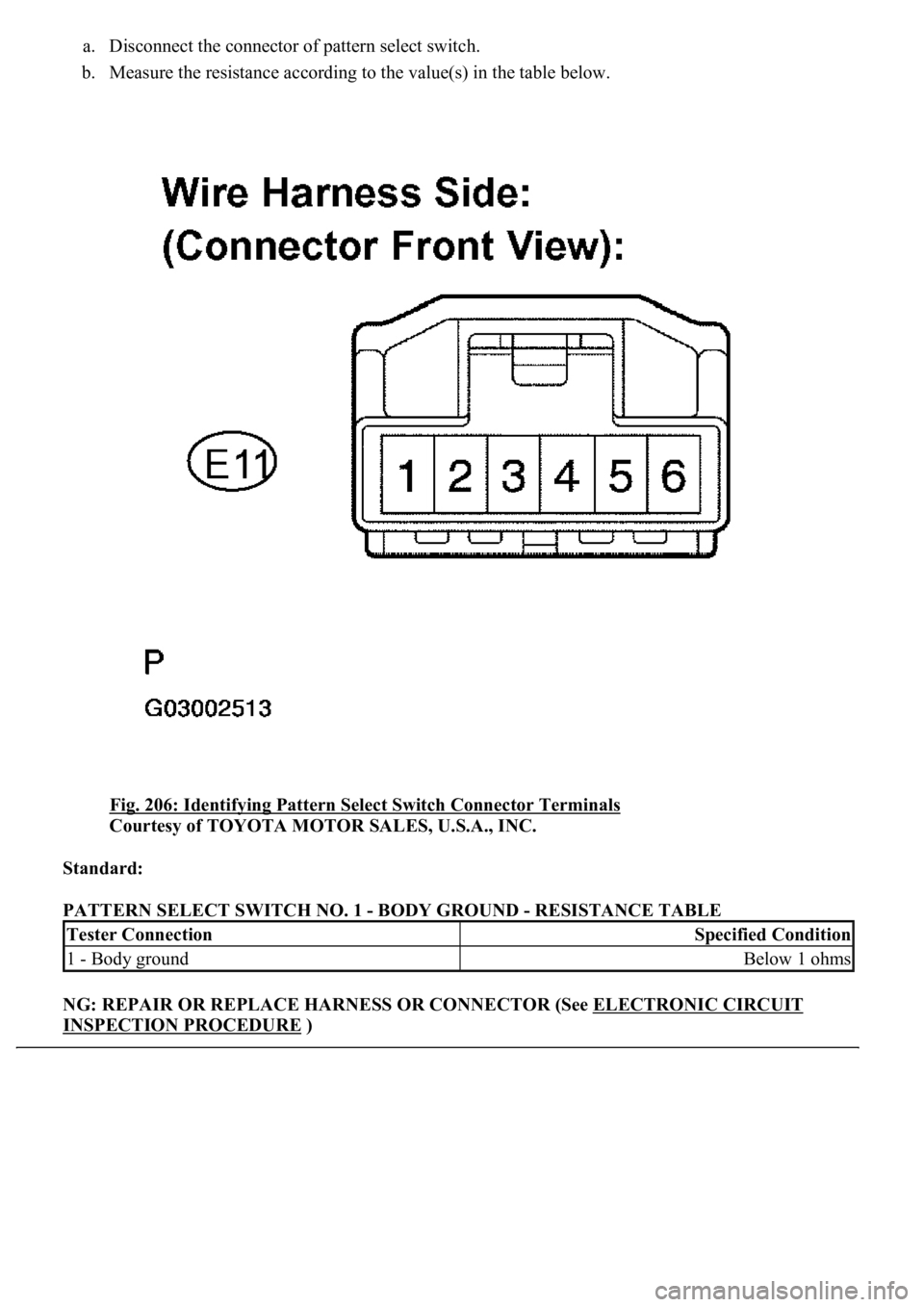
a. Disconnect the connector of pattern select switch.
b. Measure the resistance according to the value(s) in the table below.
Fig. 206: Identifying Pattern Select Switch Connector Terminals
Courtesy of TOYOTA MOTOR SALES, U.S.A., INC.
Standard:
PATTERN SELECT SWITCH NO. 1 - BODY GROUND - RESISTANCE TABLE
NG: REPAIR OR REPLACE HARNESS OR CONNECTOR (See ELECTRONIC CIRCUIT
INSPECTION PROCEDURE )
Tester ConnectionSpecified Condition
1 - Body groundBelow 1 ohms
Page 2902 of 4500
OK: Go to next step
3.INSPECT PATTERN SELECT SWITCH ASSY NO. 1
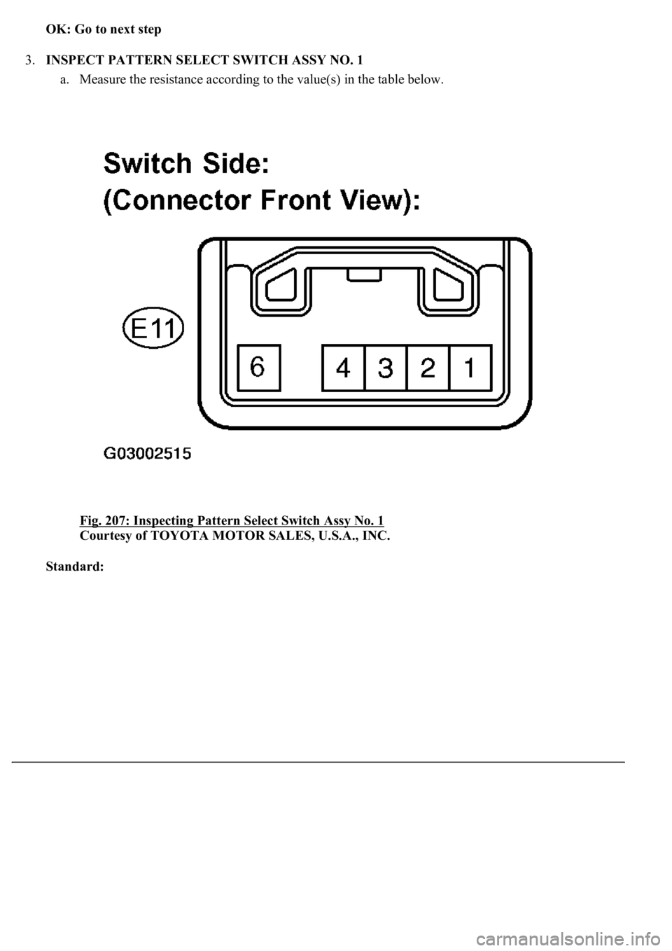
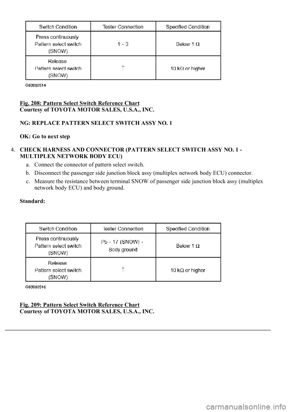
a. Measure the resistance according to the value(s) in the table below.
Fig. 207: Inspecting Pattern Select Switch Assy No. 1
Courtesy of TOYOTA MOTOR SALES, U.S.A., INC.
Standard:
Page 2903 of 4500
Fig. 208: Pattern Select Switch Reference Chart
Courtesy of TOYOTA MOTOR SALES, U.S.A., INC.
NG: REPLACE PATTERN SELECT SWITCH ASSY NO. 1
OK: Go to next step
4.CHECK HARNESS AND CONNECTOR (PATTERN SELECT SWITCH ASSY NO. 1 -
MULTIPLEX NETWORK BODY ECU)
a. Connect the connector of pattern select switch.
b. Disconnect the passenger side junction block assy (multiplex network body ECU) connector.
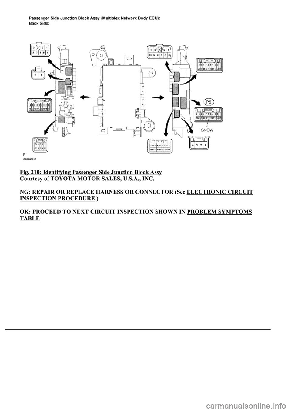
c. Measure the resistance between terminal SNOW of passenger side junction block assy (multiplex
network body ECU) and body ground.
Standard:
Fig. 209: Pattern Select Switch Reference Chart
Courtesy of TOYOTA MOTOR SALES, U.S.A., INC.
Page 2904 of 4500
Fig. 210: Identifying Passenger Side Junction Block Assy
Courtesy of TOYOTA MOTOR SALES, U.S.A., INC.
NG: REPAIR OR REPLACE HARNESS OR CONNECTOR (See ELECTRONIC CIRCUIT
INSPECTION PROCEDURE )
OK: PROCEED TO NEXT CIRCUIT INSPECTION SHOWN IN PROBLEM SYMPTOMS
TABLE
Page 2905 of 4500
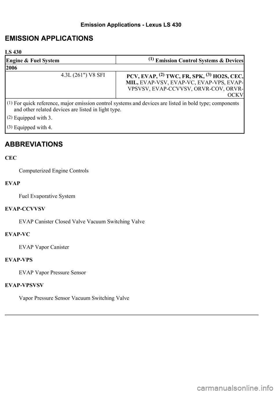
LS 430
CEC
Computerized Engine Controls
EVAP
Fuel Evaporative System
EVAP-CCVVSV
EVAP Canister Closed Valve Vacuum Switching Valve
EVAP-VC
EVAP Vapor Canister
EVAP-VPS
EVAP Vapor Pressure Sensor
EVAP-VPSVSV
Vapor Pressure Sensor Vacuum Switching Valve
Engine & Fuel System(1) Emission Control Systems & Devices
2006
4.3L (261") V8 SFIPCV, EVAP, (2) TWC, FR, SPK, (3) HO2S, CEC,
MIL, EVAP-VSV, EVAP-VC, EVAP-VPS, EVAP-
VPSVSV, EVAP-CCVVSV, ORVR-COV, ORVR-
OCKV
(1)For quick reference, major emission control systems and devices are listed in bold type; components
and other related devices are listed in light type.
(2)Equipped with 3.
(3)Equipped with 4.
Page 2906 of 4500
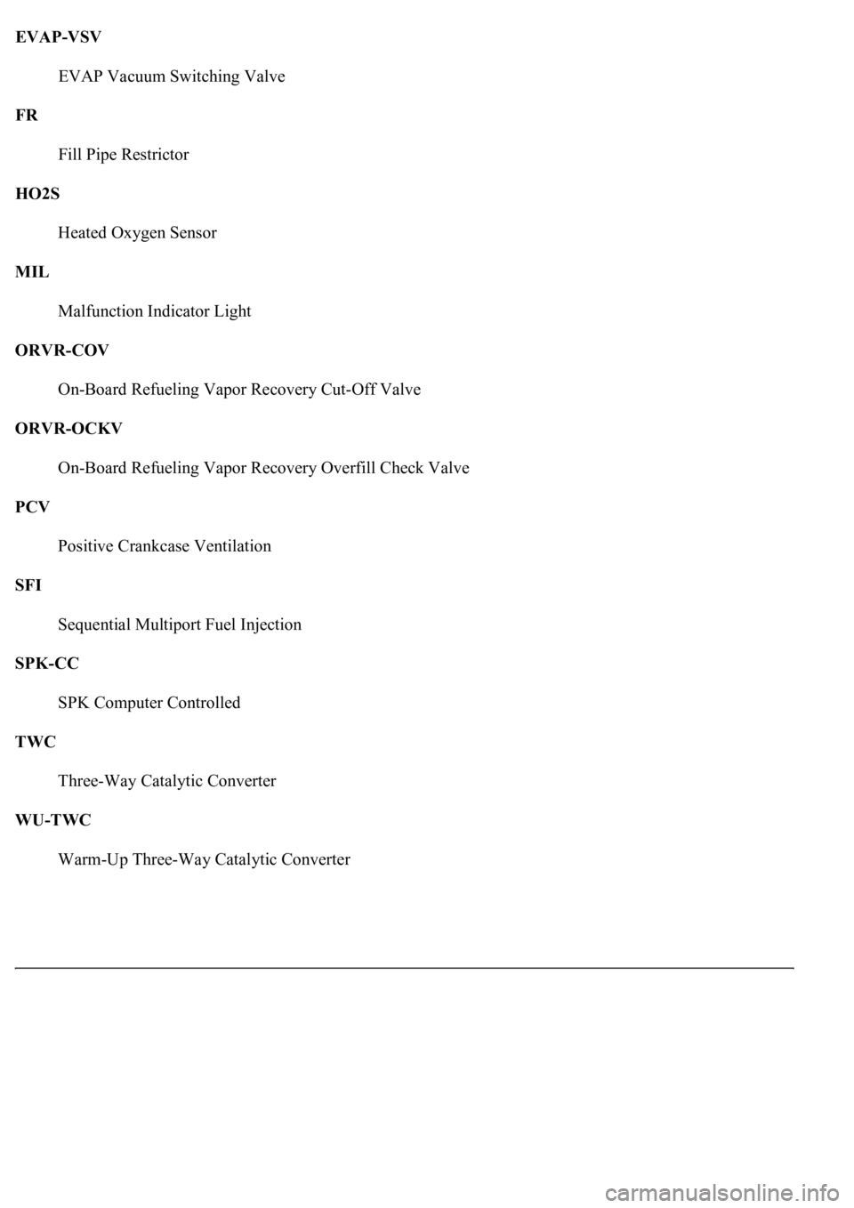
EVAP-VSV
EVAP Vacuum Switching Valve
FR
Fill Pipe Restrictor
HO2S
Heated Oxygen Sensor
MIL
Malfunction Indicator Light
ORVR-COV
On-Board Refueling Vapor Recovery Cut-Off Valve
ORVR-OCKV
On-Board Refueling Vapor Recovery Overfill Check Valve
PCV
Positive Crankcase Ventilation
SFI
Sequential Multiport Fuel Injection
SPK-CC
SPK Computer Controlled
TWC
Three-Way Catalytic Converter
WU-TWC
Warm-Up Three-Wa
y Catalytic Converter
Page 2907 of 4500
Page 2908 of 4500
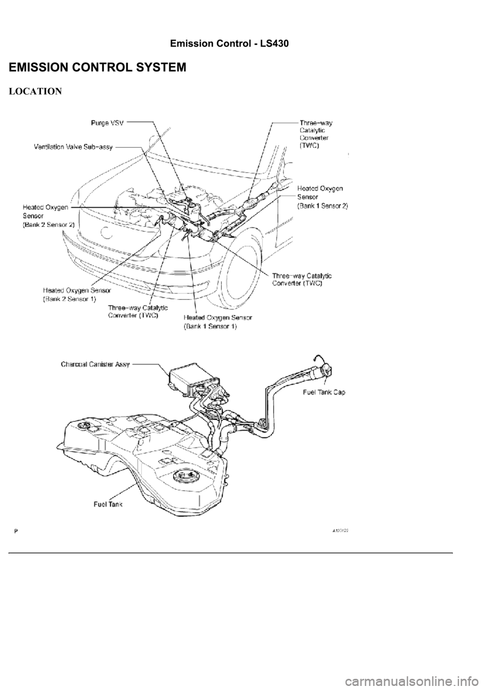
Fig. 1: Identifying Components Location Emission Control System
Courtesy of TOYOTA MOTOR SALES, U.S.A., INC.
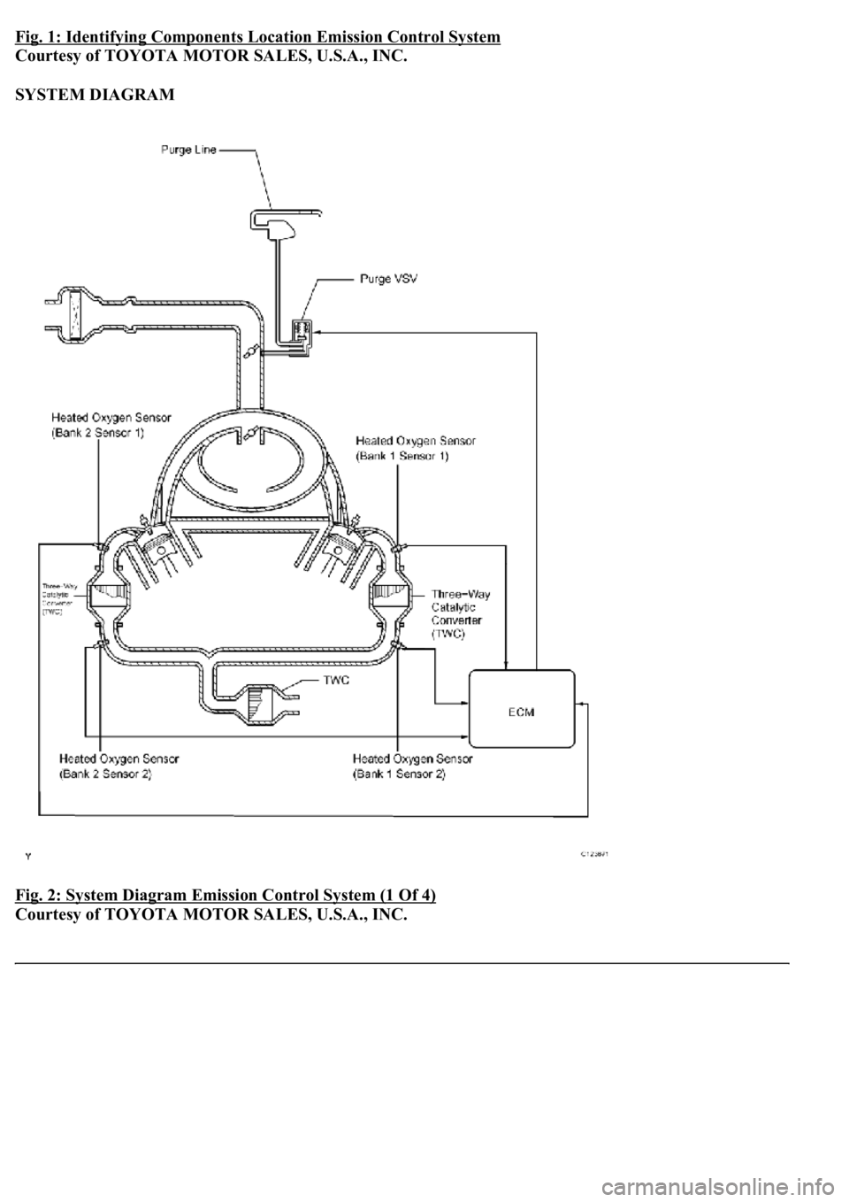
SYSTEM DIAGRAM
Fig. 2: System Diagram Emission Control System (1 Of 4)
Courtesy of TOYOTA MOTOR SALES, U.S.A., INC.
Page 2909 of 4500
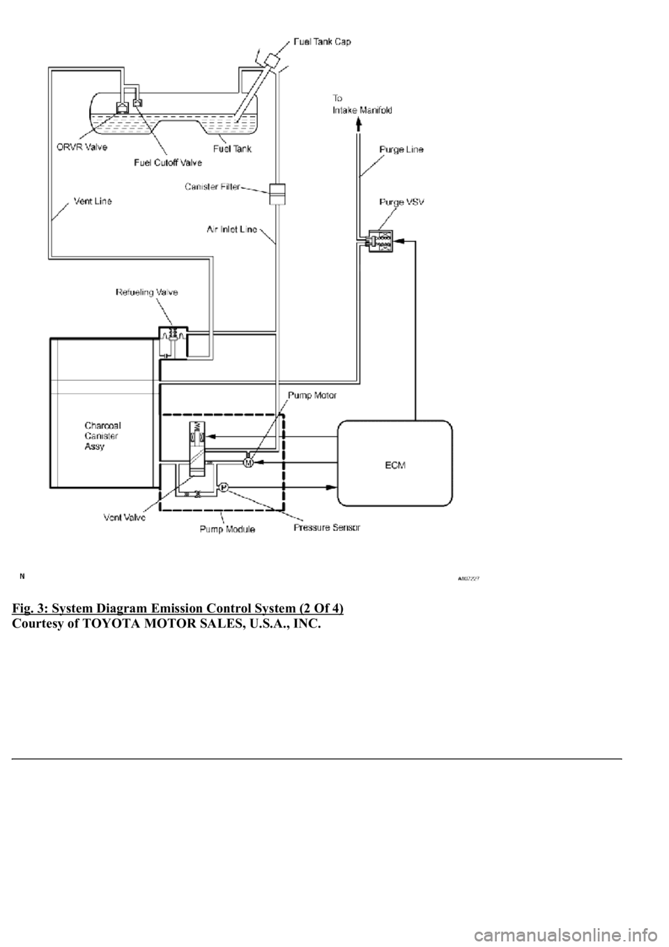
Fig. 3: System Diagram Emission Control System (2 Of 4)
Courtesy of TOYOTA MOTOR SALES, U.S.A., INC.
Page 2910 of 4500
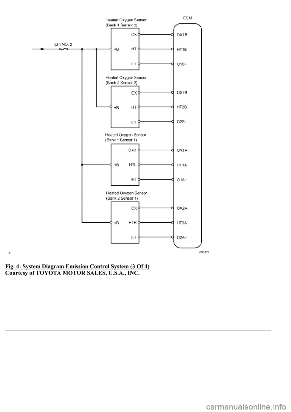
Fig. 4: System Diagram Emission Control System (3 Of 4)
Courtesy of TOYOTA MOTOR SALES, U.S.A., INC.
Trending: sport mode, fuel cap, tire size, check oil, ignition, instrument cluster, Identifying ac
