LEXUS LS430 2003 Factory Repair Manual
Manufacturer: LEXUS, Model Year: 2003,
Model line: LS430,
Model: LEXUS LS430 2003
Pages: 4500, PDF Size: 87.45 MB
LEXUS LS430 2003 Factory Repair Manual
LS430 2003
LEXUS
LEXUS
https://www.carmanualsonline.info/img/36/57050/w960_57050-0.png
LEXUS LS430 2003 Factory Repair Manual
Trending: change time, fuse box location, service reset, Spark plug firing order, Door lock, Soft hard, torque
Page 2931 of 4500
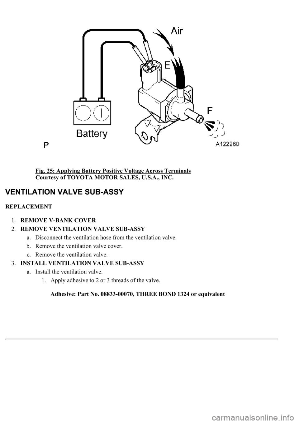
Fig. 25: Applying Battery Positive Voltage Across Terminals
Courtesy of TOYOTA MOTOR SALES, U.S.A., INC.
REPLACEMENT
1.REMOVE V-BANK COVER
2.REMOVE VENTILATION VALVE SUB-ASSY
a. Disconnect the ventilation hose from the ventilation valve.
b. Remove the ventilation valve cover.
c. Remove the ventilation valve.
3.INSTALL VENTILATION VALVE SUB-ASSY
a. Install the ventilation valve.
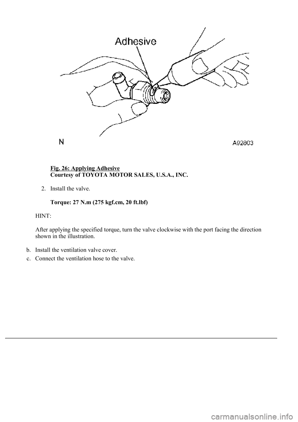
1. Apply adhesive to 2 or 3 threads of the valve.
Adhesive: Part No. 08833-00070, THREE BOND 1324 or equivalent
Page 2932 of 4500
Fig. 26: Applying Adhesive
Courtesy of TOYOTA MOTOR SALES, U.S.A., INC.
2. Install the valve.
Torque: 27 N.m (275 kgf.cm, 20 ft.lbf)
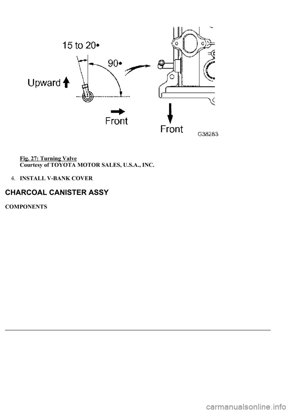
HINT:
After applying the specified torque, turn the valve clockwise with the port facing the direction
shown in the illustration.
b. Install the ventilation valve cover.
c. Connect the ventilation hose to the valve.
Page 2933 of 4500
Fig. 27: Turning Valve
Courtesy of TOYOTA MOTOR SALES, U.S.A., INC.
4.INSTALL V-BANK COVER
COMPONENTS
Page 2934 of 4500
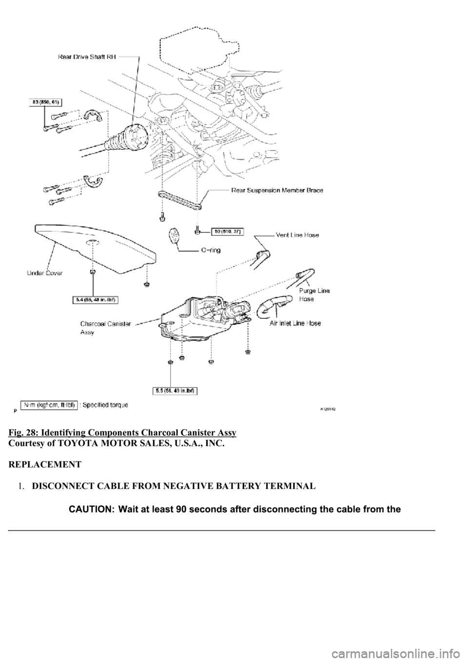
Fig. 28: Identifying Components Charcoal Canister Assy
Courtesy of TOYOTA MOTOR SALES, U.S.A., INC.
REPLACEMENT
1.DISCONNECT CABLE FROM NEGATIVE BATTERY TERMINAL
Page 2935 of 4500
2.DISCONNECT REAR DRIVE SHAFT RH (See REAR DRIVE SHAFT )
3.REMOVE CHARCOAL CANISTER ASSY
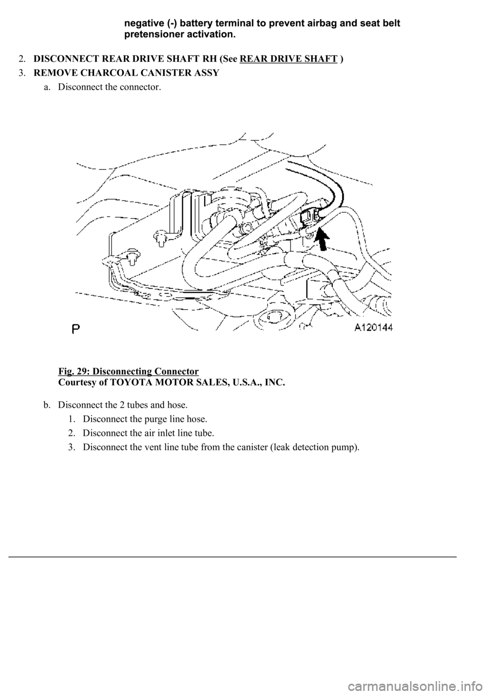
a. Disconnect the connector.
Fig. 29: Disconnecting Connector
Courtesy of TOYOTA MOTOR SALES, U.S.A., INC.
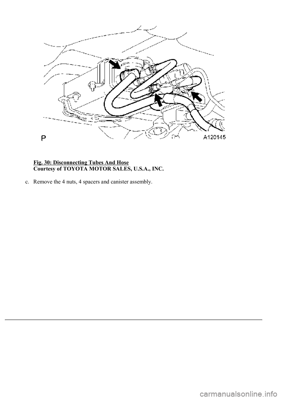
b. Disconnect the 2 tubes and hose.
1. Disconnect the purge line hose.
2. Disconnect the air inlet line tube.
3. Disconnect the vent line tube from the canister (leak detection pump).
Page 2936 of 4500
Fig. 30: Disconnecting Tubes And Hose
Courtesy of TOYOTA MOTOR SALES, U.S.A., INC.
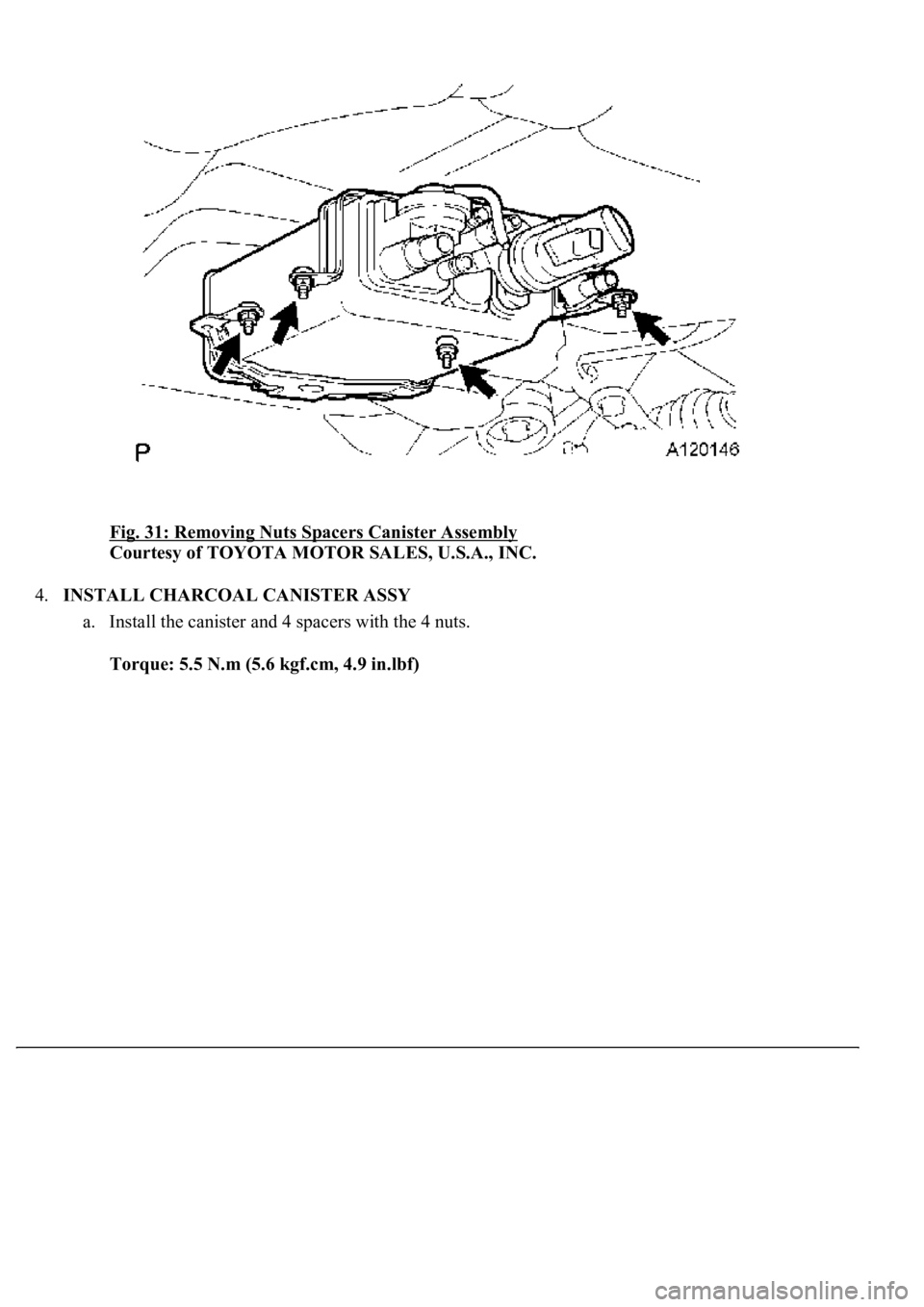
c. Remove the 4 nuts, 4 spacers and canister assembly.
Page 2937 of 4500
Fig. 31: Removing Nuts Spacers Canister Assembly
Courtesy of TOYOTA MOTOR SALES, U.S.A., INC.
4.INSTALL CHARCOAL CANISTER ASSY
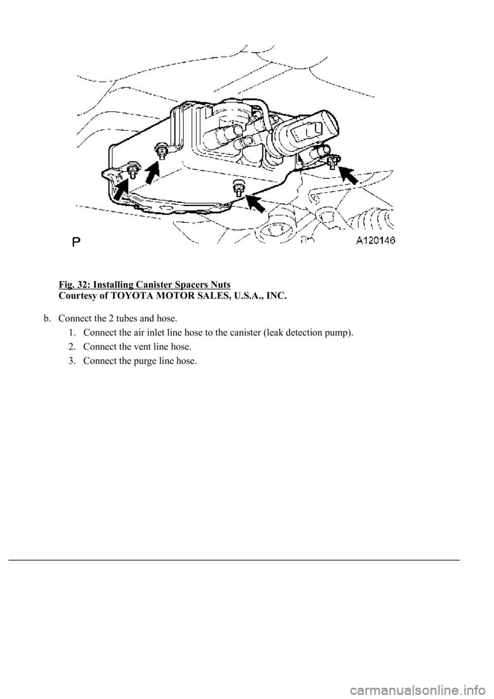
a. Install the canister and 4 spacers with the 4 nuts.
Torque: 5.5 N.m (5.6 kgf.cm, 4.9 in.lbf)
Page 2938 of 4500
Fig. 32: Installing Canister Spacers Nuts
Courtesy of TOYOTA MOTOR SALES, U.S.A., INC.
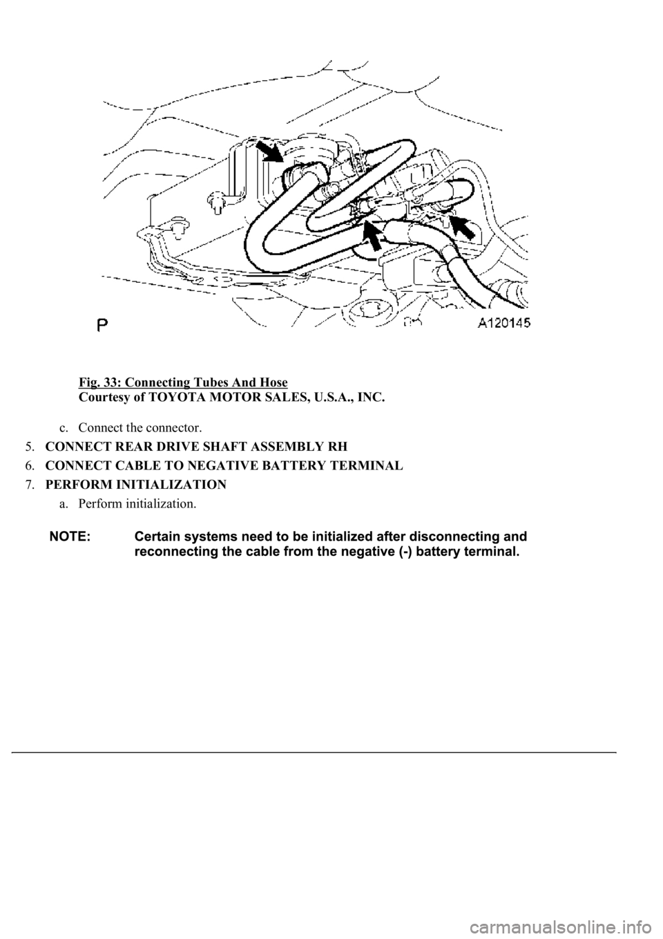
b. Connect the 2 tubes and hose.
1. Connect the air inlet line hose to the canister (leak detection pump).
2. Connect the vent line hose.
3. Connect the pur
ge line hose.
Page 2939 of 4500
Fig. 33: Connecting Tubes And Hose
Courtesy of TOYOTA MOTOR SALES, U.S.A., INC.
c. Connect the connector.
5.CONNECT REAR DRIVE SHAFT ASSEMBLY RH
6.CONNECT CABLE TO NEGATIVE BATTERY TERMINAL
7.PERFORM INITIALIZATION
a. Perform initialization.
Page 2940 of 4500
Fig. 34: Locating Nuts
Courtesy of TOYOTA MOTOR SALES, U.S.A., INC.
8.CONNECT REAR DRIVE SHAFT RH (See REAR DRIVE SHAFT
)
Trending: wipers, fuel system, spark plugs replace, fuel type, Door lock actuator, electronic modulated, Spark plug firing order
