LEXUS LS430 2003 Factory Repair Manual
Manufacturer: LEXUS, Model Year: 2003,
Model line: LS430,
Model: LEXUS LS430 2003
Pages: 4500, PDF Size: 87.45 MB
LEXUS LS430 2003 Factory Repair Manual
LS430 2003
LEXUS
LEXUS
https://www.carmanualsonline.info/img/36/57050/w960_57050-0.png
LEXUS LS430 2003 Factory Repair Manual
Trending: AC Compressor control valve, bulb, headrest, warning lights, evap, washer fluid, torque
Page 2911 of 4500
Fig. 5: System Diagram Emission Control System (4 Of 4)
Courtesy of TOYOTA MOTOR SALES, U.S.A., INC.
ON-VEHICLE INSPECTION
1.INSPECT A/F COMPENSATION SYSTEM
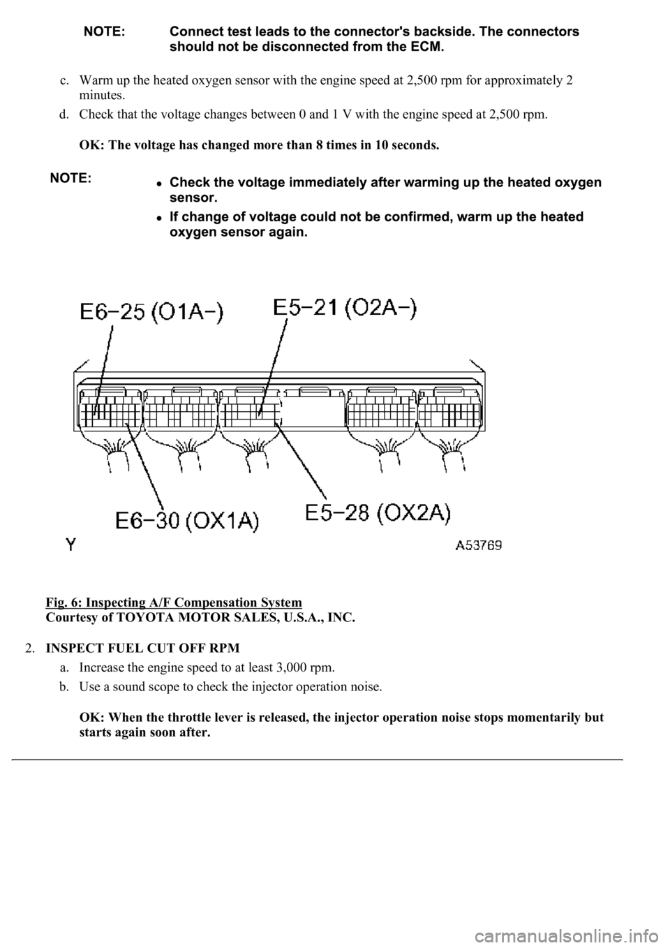
a. Connect the hand-held tester to terminals E6-30 (OX1A) and E6-25 (O1A-) of the ECM.
b. Connect the hand-held tester to terminals E5-28 (OX2A) and E5-21 (02A-) of the ECM.
Page 2912 of 4500
c. Warm up the heated oxygen sensor with the engine speed at 2,500 rpm for approximately 2
minutes.
d. Check that the voltage changes between 0 and 1 V with the engine speed at 2,500 rpm.
OK: The voltage has changed more than 8 times in 10 seconds.
Fig. 6: Inspecting A/F Compensation System
Courtesy of TOYOTA MOTOR SALES, U.S.A., INC.
2.INSPECT FUEL CUT OFF RPM
a. Increase the engine speed to at least 3,000 rpm.
b. Use a sound scope to check the injector operation noise.
OK: When the throttle lever is released, the injector operation noise stops momentarily but
starts again soon after.
Page 2913 of 4500
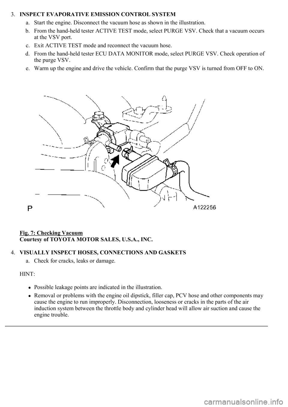
3.INSPECT EVAPORATIVE EMISSION CONTROL SYSTEM
a. Start the engine. Disconnect the vacuum hose as shown in the illustration.
b. From the hand-held tester ACTIVE TEST mode, select PURGE VSV. Check that a vacuum occurs
at the VSV port.
c. Exit ACTIVE TEST mode and reconnect the vacuum hose.
d. From the hand-held tester ECU DATA MONITOR mode, select PURGE VSV. Check operation of
the purge VSV.
e. Warm up the engine and drive the vehicle. Confirm that the purge VSV is turned from OFF to ON.
Fig. 7: Checking Vacuum
Courtesy of TOYOTA MOTOR SALES, U.S.A., INC.
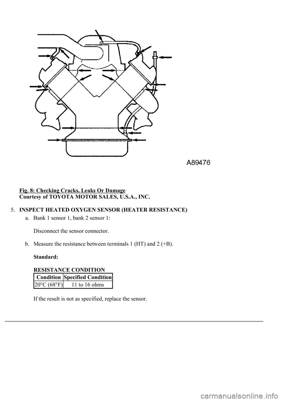
4.VISUALLY INSPECT HOSES, CONNECTIONS AND GASKETS
a. Check for cracks, leaks or damage.
HINT:
Possible leakage points are indicated in the illustration.
Removal or problems with the engine oil dipstick, filler cap, PCV hose and other components may
cause the engine to run improperly. Disconnection, looseness or cracks in the parts of the air
induction system between the throttle body and cylinder head will allow air suction and cause the
engine trouble.
Page 2914 of 4500
Fig. 8: Checking Cracks, Leaks Or Damage
Courtesy of TOYOTA MOTOR SALES, U.S.A., INC.
5.INSPECT HEATED OXYGEN SENSOR (HEATER RESISTANCE)
a. Bank 1 sensor 1, bank 2 sensor 1:
Disconnect the sensor connector.
b. Measure the resistance between terminals 1 (HT) and 2 (+B).
Standard:
RESISTANCE CONDITION
If the result is not as specified, replace the sensor.
ConditionSpecified Condition
20°C (68°F)11 to 16 ohms
Page 2915 of 4500
Fig. 9: Identifying Connector Terminals Heated Oxygen Sensor
Courtesy of TOYOTA MOTOR SALES, U.S.A., INC.
c. Bank 1 sensor 2, bank 2 sensor 2:
Disconnect the sensor connector.
d. Measure the resistance between terminals 1 (HT) and 2 (+B).
Standard:
RESISTANCE CONDITION
If the result is not as specified, replace the sensor.
ConditionSpecified Condition
20°C (68°F)11 to 16 ohms
Page 2916 of 4500
Fig. 10: Identifying Connector Terminals Heated Oxygen Sensor
Courtesy of TOYOTA MOTOR SALES, U.S.A., INC.
INSPECTION
1.INSPECT CHARCOAL CANISTER ASSY
a. Visually check the charcoal canister for cracks or damage.
If cracks or damage are found, replace the canister.
Page 2917 of 4500
Fig. 11: Checking Charcoal Canister For Cracks Or Damage
Courtesy of TOYOTA MOTOR SALES, U.S.A., INC.
b. Check canister operation.
1. With the purge port closed, blow 0.39 kPa (4.0 kgf/cm
2 , 0.06 psi) of air into the vent port,
and check that air flows from the air inlet port.
If the result is not as specified, replace the canister.
Page 2918 of 4500
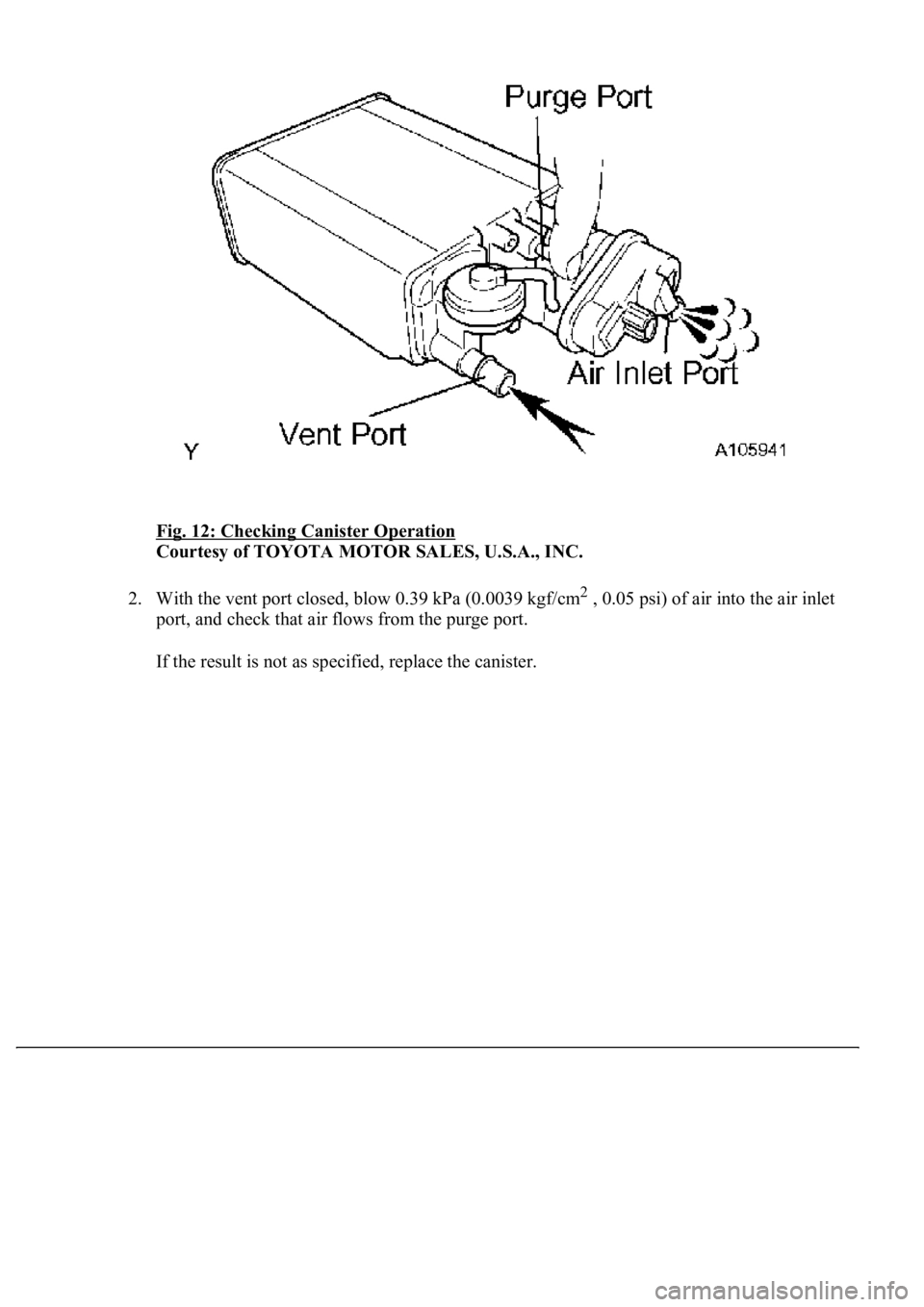
Fig. 12: Checking Canister Operation
Courtesy of TOYOTA MOTOR SALES, U.S.A., INC.
2. With the vent port closed, blow 0.39 kPa (0.0039 kgf/cm
2 , 0.05 psi) of air into the air inlet
<0053005200550057000f000300440051004700030046004b00480046004e00030057004b0044005700030044004c005500030049004f0052005a00560003004900550052005000030057004b00480003005300580055004a00480003005300520055005700
110003[
If the result is not as specified, replace the canister.
Page 2919 of 4500
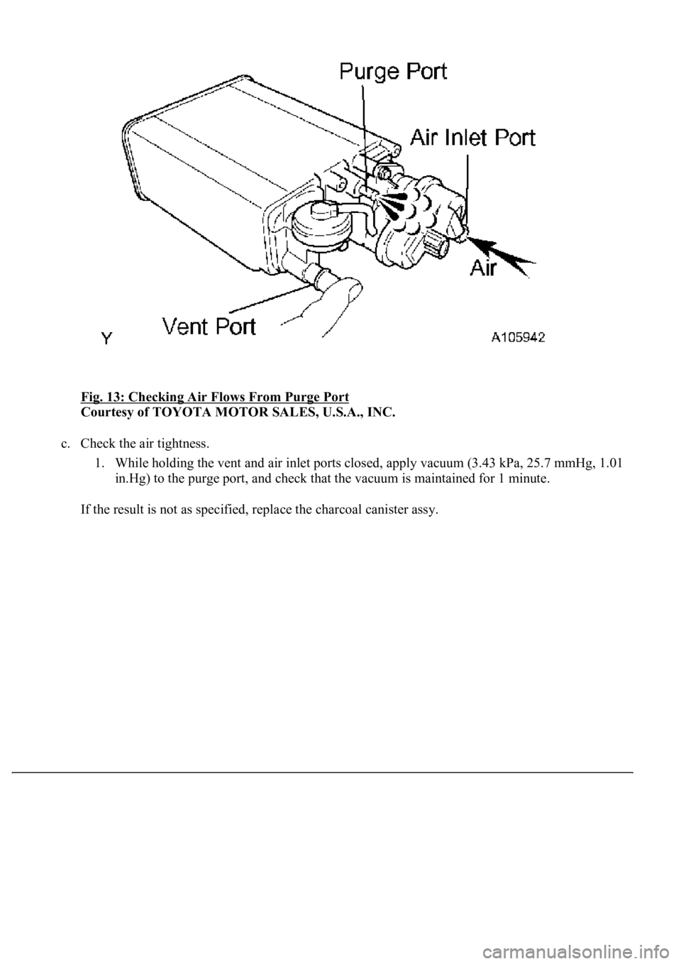
Fig. 13: Checking Air Flows From Purge Port
Courtesy of TOYOTA MOTOR SALES, U.S.A., INC.
c. Check the air tightness.
1. While holding the vent and air inlet ports closed, apply vacuum (3.43 kPa, 25.7 mmHg, 1.01
in.Hg) to the purge port, and check that the vacuum is maintained for 1 minute.
If the result is not as specified, replace the charcoal canister assy.
Page 2920 of 4500
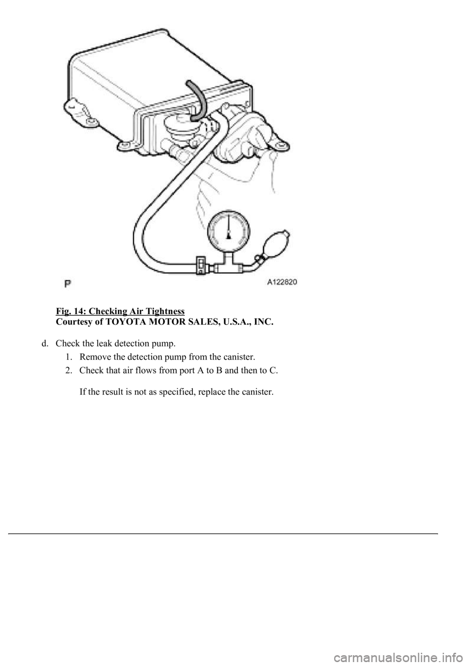
Fig. 14: Checking Air Tightness
Courtesy of TOYOTA MOTOR SALES, U.S.A., INC.
d. Check the leak detection pump.
1. Remove the detection pump from the canister.
2. Check that air flows from port A to B and then to C.
If the result is not as specified, replace the canister.
Trending: ad blue, ABS, fuse, content, airbag off, brake fluid, child lock
