LEXUS LS430 2003 Factory Repair Manual
Manufacturer: LEXUS, Model Year: 2003,
Model line: LS430,
Model: LEXUS LS430 2003
Pages: 4500, PDF Size: 87.45 MB
LEXUS LS430 2003 Factory Repair Manual
LS430 2003
LEXUS
LEXUS
https://www.carmanualsonline.info/img/36/57050/w960_57050-0.png
LEXUS LS430 2003 Factory Repair Manual
Trending: belt, tow, garage door opener, oil pressure, wipers, fuse, fuses
Page 2941 of 4500
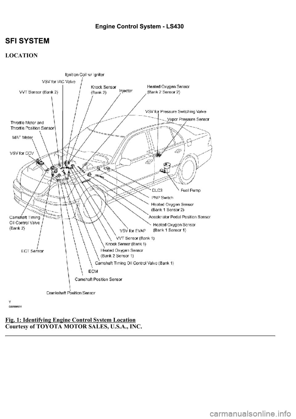
LOCATION
Fig. 1: Identifying Engine Control System Location
Courtesy of TOYOTA MOTOR SALES, U.S.A., INC.
Page 2942 of 4500
SYSTEM DIAGRAM
Engine control system is determined by the ECM based on signals from various sensors.
Fig. 2: Engine Control
- System Diagram
Courtesy of TOYOTA MOTOR SALES, U.S.A., INC.
Page 2943 of 4500
ON-VEHICLE INSPECTION
1.INSPECTION THROTTLE BODY
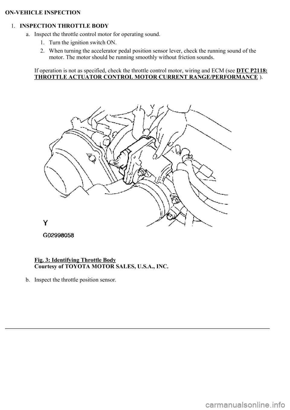
a. Inspect the throttle control motor for operating sound.
1. Turn the ignition switch ON.
2. When turning the accelerator pedal position sensor lever, check the running sound of the
motor. The motor should be running smoothly without friction sounds.
If operation is not as specified, check the throttle control motor, wiring and ECM (see DTC P2118:
THROTTLE ACTUATOR CONTROL MOTOR CURRENT RANGE/PERFORMANCE ).
Fig. 3: Identifying Throttle Body
Courtesy of TOYOTA MOTOR SALES, U.S.A., INC.
b. Inspect the throttle position sensor.
Page 2944 of 4500
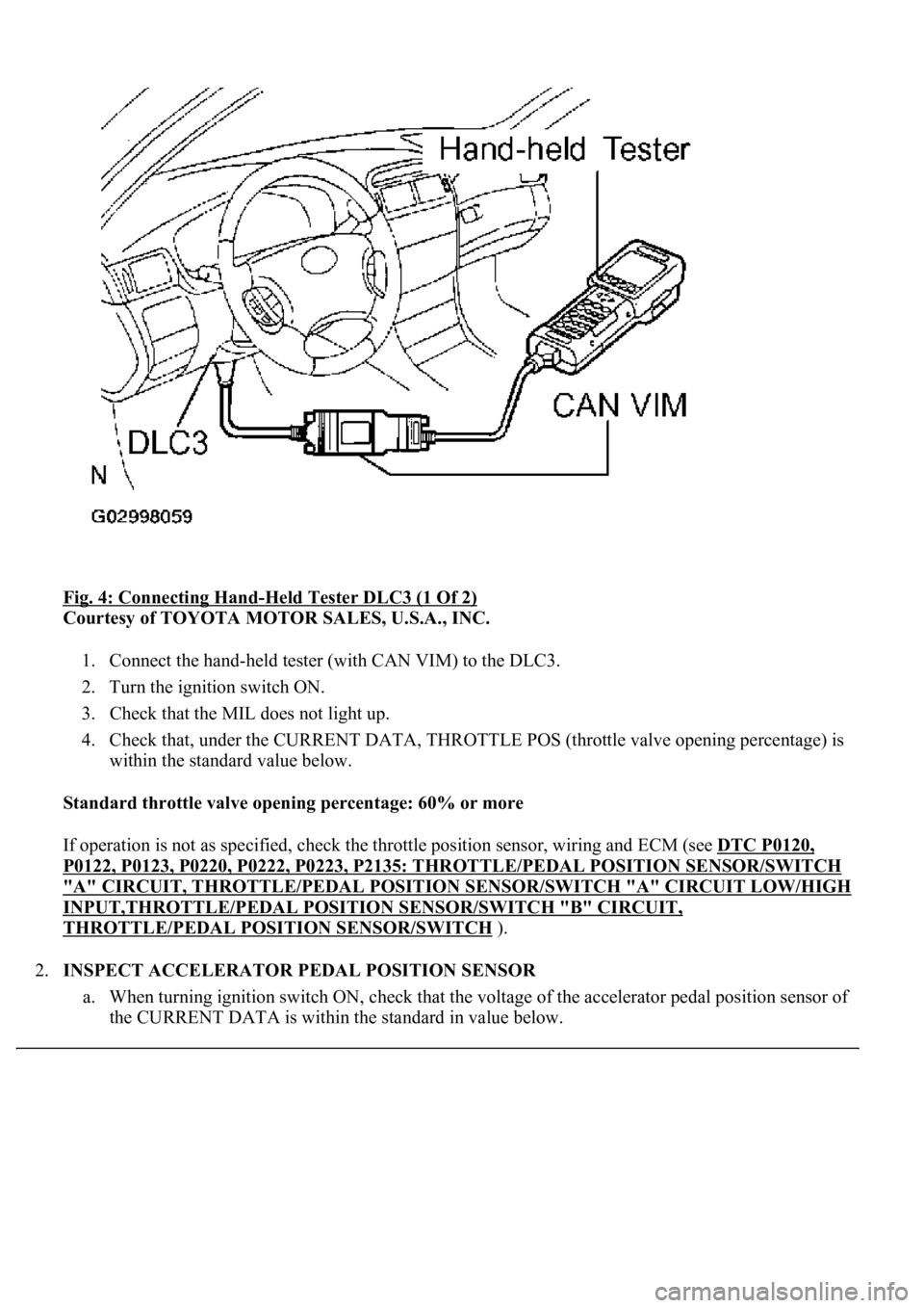
Fig. 4: Connecting Hand-Held Tester DLC3 (1 Of 2)
Courtesy of TOYOTA MOTOR SALES, U.S.A., INC.
1. Connect the hand-held tester (with CAN VIM) to the DLC3.
2. Turn the ignition switch ON.
3. Check that the MIL does not light up.
4. Check that, under the CURRENT DATA, THROTTLE POS (throttle valve opening percentage) is
within the standard value below.
Standard throttle valve opening percentage: 60% or more
If operation is not as specified, check the throttle position sensor, wiring and ECM (see DTC P0120,
P0122, P0123, P0220, P0222, P0223, P2135: THROTTLE/PEDAL POSITION SENSOR/SWITCH
"A" CIRCUIT, THROTTLE/PEDAL POSITION SENSOR/SWITCH "A" CIRCUIT LOW/HIGH
INPUT,THROTTLE/PEDAL POSITION SENSOR/SWITCH "B" CIRCUIT,
THROTTLE/PEDAL POSITION SENSOR/SWITCH ).
2.INSPECT ACCELERATOR PEDAL POSITION SENSOR
a. When turning ignition switch ON, check that the voltage of the accelerator pedal position sensor of
<0057004b004800030026003800350035002800310037000300270024003700240003004c00560003005a004c0057004b004c005100030057004b00480003005600570044005100470044005500470003004c0051000300590044004f005800480003004500
48004f0052005a00110003[
Page 2945 of 4500
Standard: 0.6 to 1.0 V
If the result is not as specified, replace the accelerator pedal position sensor.
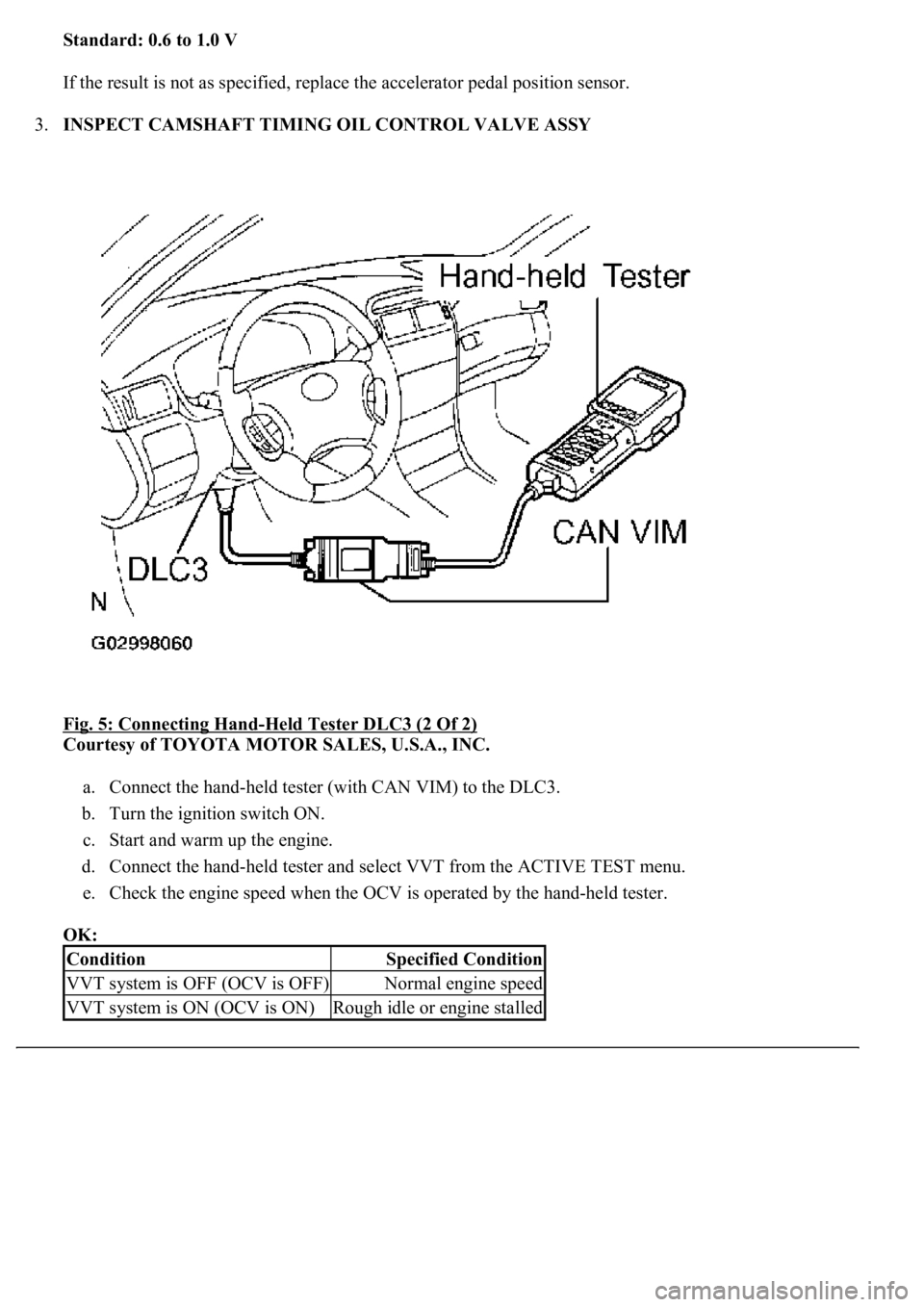
3.INSPECT CAMSHAFT TIMING OIL CONTROL VALVE ASSY
Fig. 5: Connecting Hand
-Held Tester DLC3 (2 Of 2)
Courtesy of TOYOTA MOTOR SALES, U.S.A., INC.
a. Connect the hand-held tester (with CAN VIM) to the DLC3.
b. Turn the ignition switch ON.
c. Start and warm up the engine.
d. Connect the hand-held tester and select VVT from the ACTIVE TEST menu.
e. Check the engine speed when the OCV is operated by the hand-held tester.
OK:
ConditionSpecified Condition
VVT system is OFF (OCV is OFF)Normal engine speed
VVT system is ON (OCV is ON)Rough idle or engine stalled
Page 2946 of 4500
INSPECTION
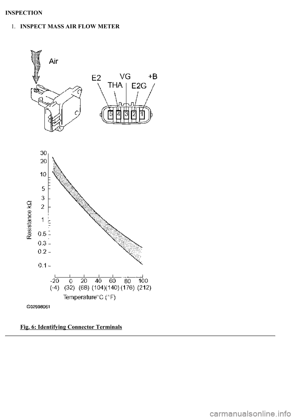
1.INSPECT MASS AIR FLOW METER
Fig. 6: Identifying Connector Terminals
Page 2947 of 4500
Courtesy of TOYOTA MOTOR SALES, U.S.A., INC.
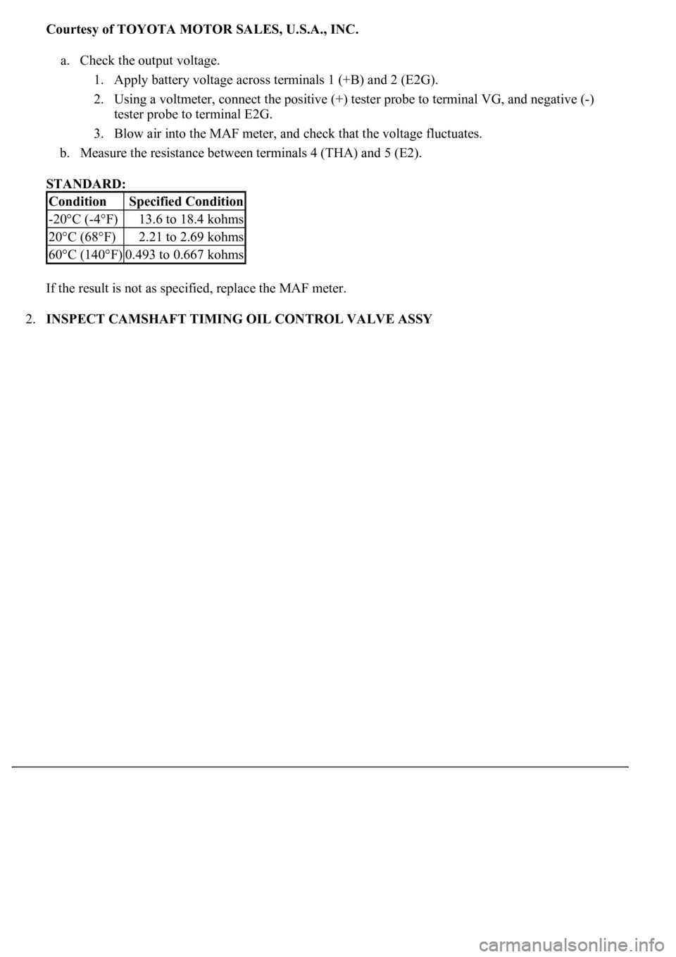
a. Check the output voltage.
1. Apply battery voltage across terminals 1 (+B) and 2 (E2G).
2. Using a voltmeter, connect the positive (+) tester probe to terminal VG, and negative (-)
tester probe to terminal E2G.
3. Blow air into the MAF meter, and check that the voltage fluctuates.
b. Measure the resistance between terminals 4 (THA) and 5 (E2).
STANDARD:
If the result is not as specified, replace the MAF meter.
2.INSPECT CAMSHAFT TIMING OIL CONTROL VALVE ASSY
ConditionSpecified Condition
-20°C (-4°F)13.6 to 18.4 kohms
20°C (68°F)2.21 to 2.69 kohms
60°C (140°F)0.493 to 0.667 kohms
Page 2948 of 4500
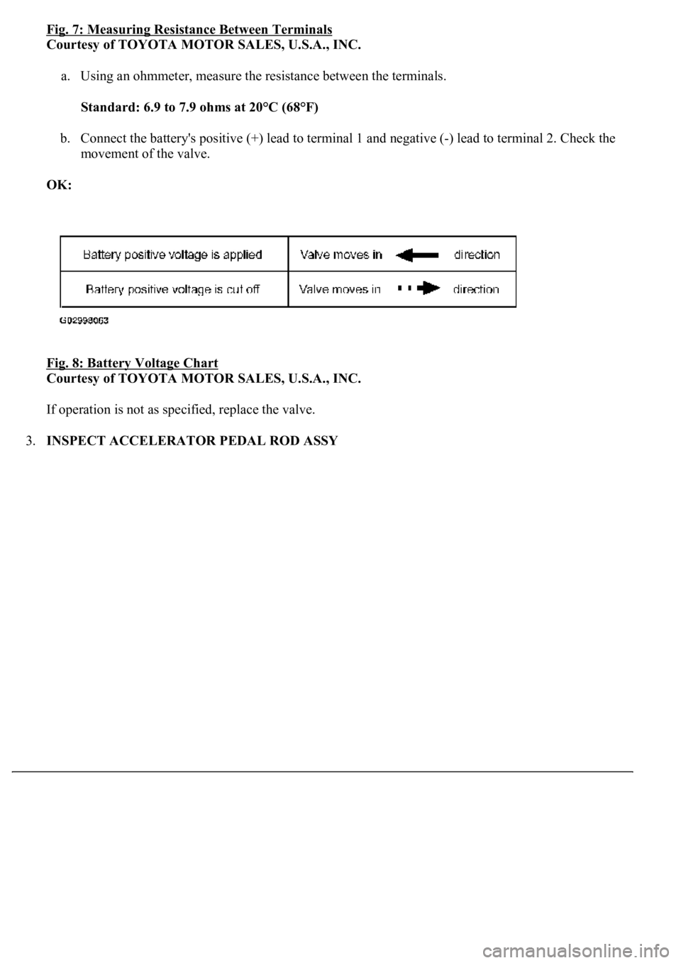
Fig. 7: Measuring Resistance Between Terminals
Courtesy of TOYOTA MOTOR SALES, U.S.A., INC.
a. Using an ohmmeter, measure the resistance between the terminals.
Standard: 6.9 to 7.9 ohms at 20°C (68°F)
b. Connect the battery's positive (+) lead to terminal 1 and negative (-) lead to terminal 2. Check the
movement of the valve.
OK:
Fig. 8: Battery Voltage Chart
Courtesy of TOYOTA MOTOR SALES, U.S.A., INC.
If operation is not as specified, replace the valve.
3.INSPECT ACCELERATOR PEDAL ROD ASSY
Page 2949 of 4500
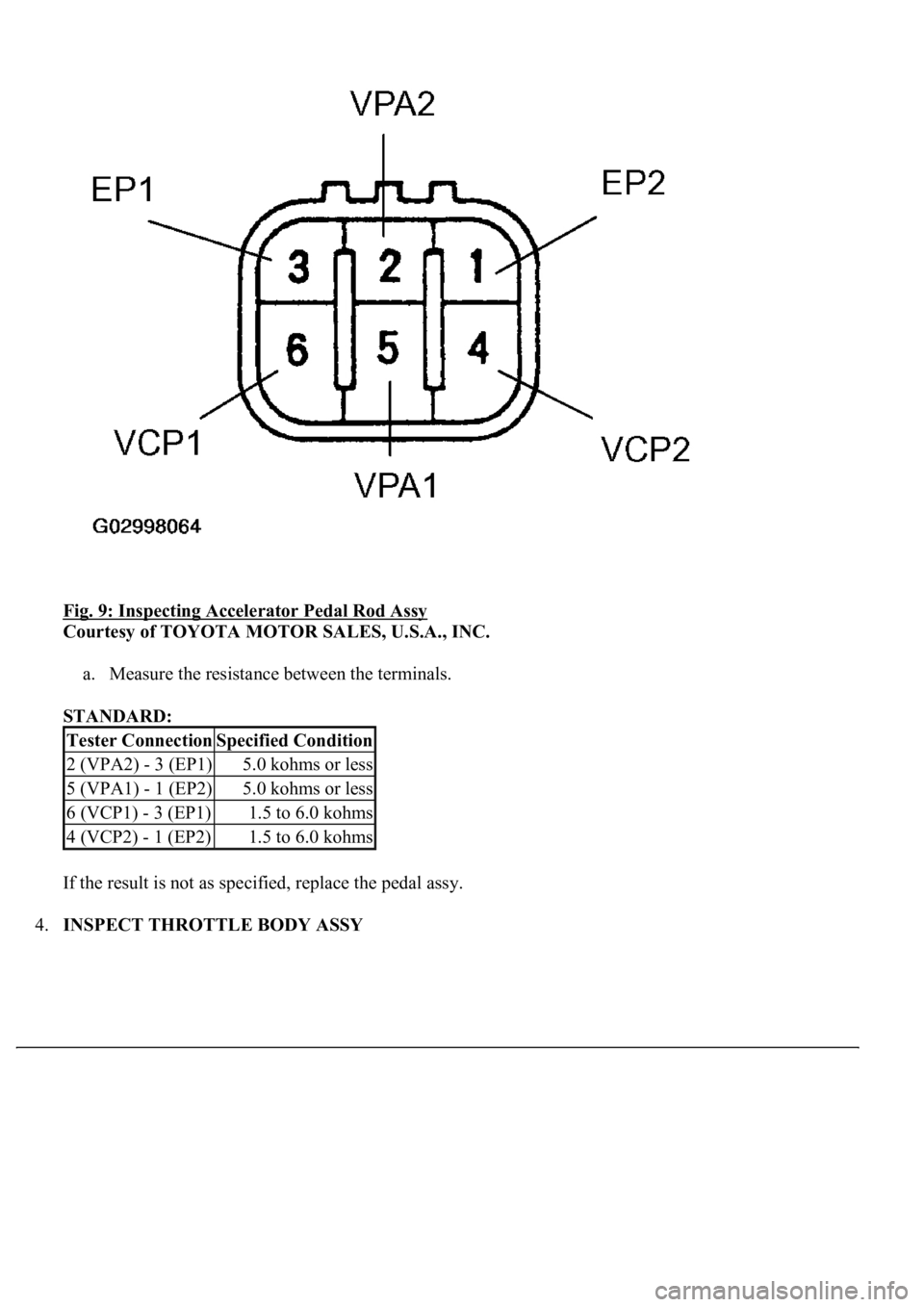
Fig. 9: Inspecting Accelerator Pedal Rod Assy
Courtesy of TOYOTA MOTOR SALES, U.S.A., INC.
a. Measure the resistance between the terminals.
STANDARD:
If the result is not as specified, replace the pedal assy.
4.INSPECT THROTTLE BODY ASSY
Tester ConnectionSpecified Condition
2 (VPA2) - 3 (EP1)5.0 kohms or less
5 (VPA1) - 1 (EP2)5.0 kohms or less
6 (VCP1) - 3 (EP1)1.5 to 6.0 kohms
4 (VCP2) - 1 (EP2)1.5 to 6.0 kohms
Page 2950 of 4500
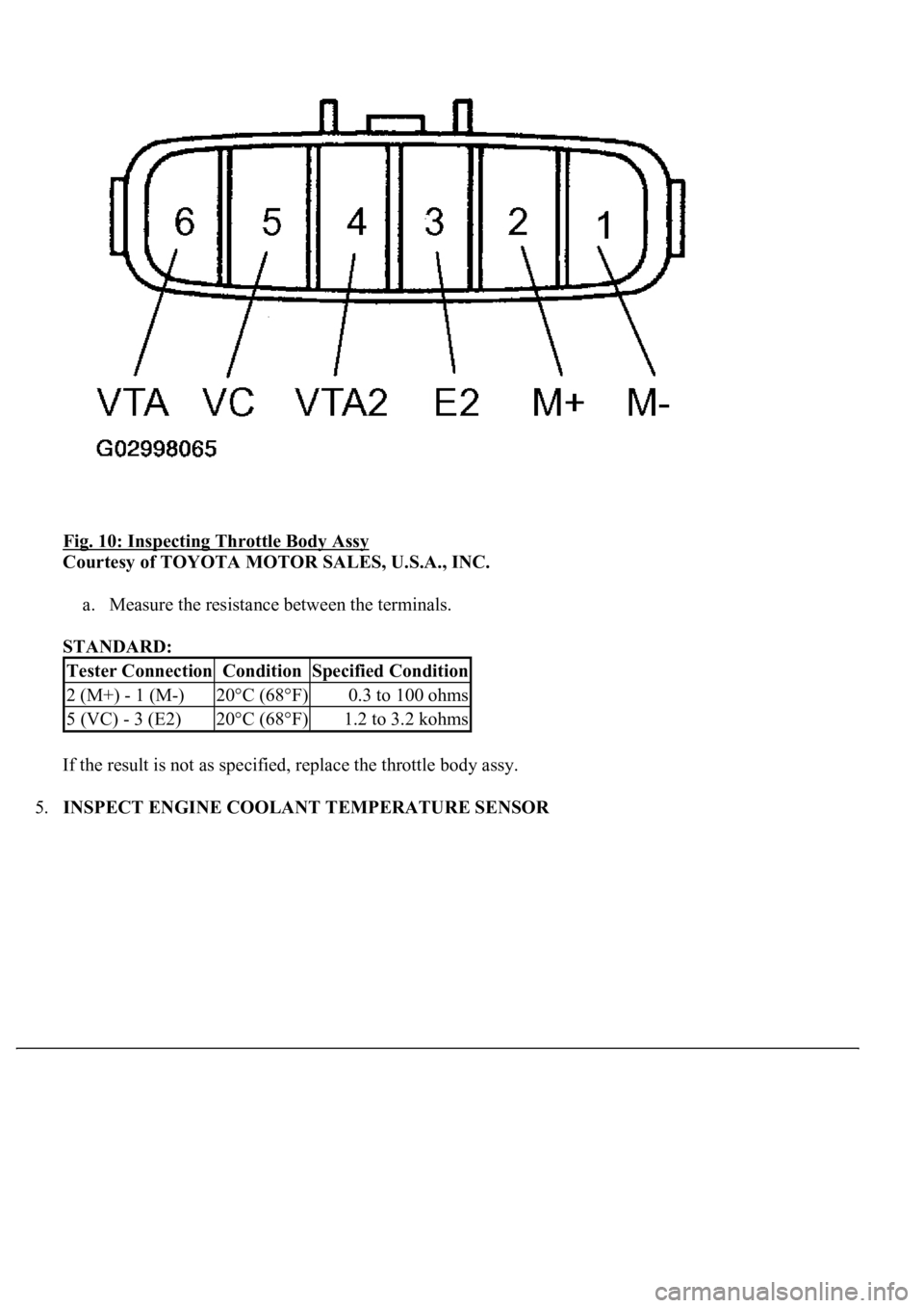
Fig. 10: Inspecting Throttle Body Assy
Courtesy of TOYOTA MOTOR SALES, U.S.A., INC.
a. Measure the resistance between the terminals.
STANDARD:
If the result is not as specified, replace the throttle body assy.
5.INSPECT ENGINE COOLANT TEMPERATURE SENSOR
Tester ConnectionConditionSpecified Condition
2 (M+) - 1 (M-)20°C (68°F)0.3 to 100 ohms
5 (VC) - 3 (E2)20°C (68°F)1.2 to 3.2 kohms
Trending: Ecm, seats, TPMS, steering interlock cable, service interval, battery replacement, Expansion Valve
