LEXUS LS430 2003 Factory Repair Manual
Manufacturer: LEXUS, Model Year: 2003,
Model line: LS430,
Model: LEXUS LS430 2003
Pages: 4500, PDF Size: 87.45 MB
LEXUS LS430 2003 Factory Repair Manual
LS430 2003
LEXUS
LEXUS
https://www.carmanualsonline.info/img/36/57050/w960_57050-0.png
LEXUS LS430 2003 Factory Repair Manual
Trending: park assist, differential, steering, Absorber suspension, buttons, drain bolt, battery
Page 3251 of 4500
attempt to use the hand-held tester. If the screen displays the message UNABLE TO CONNECT TO
VEHICLE, there is a problem either with the vehicle or with the tester.
If communication is normal when the tester is connected to another vehicle, inspect the DLC3 of
the original vehicle.
If communication is still impossible when the tester is connected to another vehicle, the problem is
probably in the tester itself. Consult the Service Department listed in the tester's instruction manual.
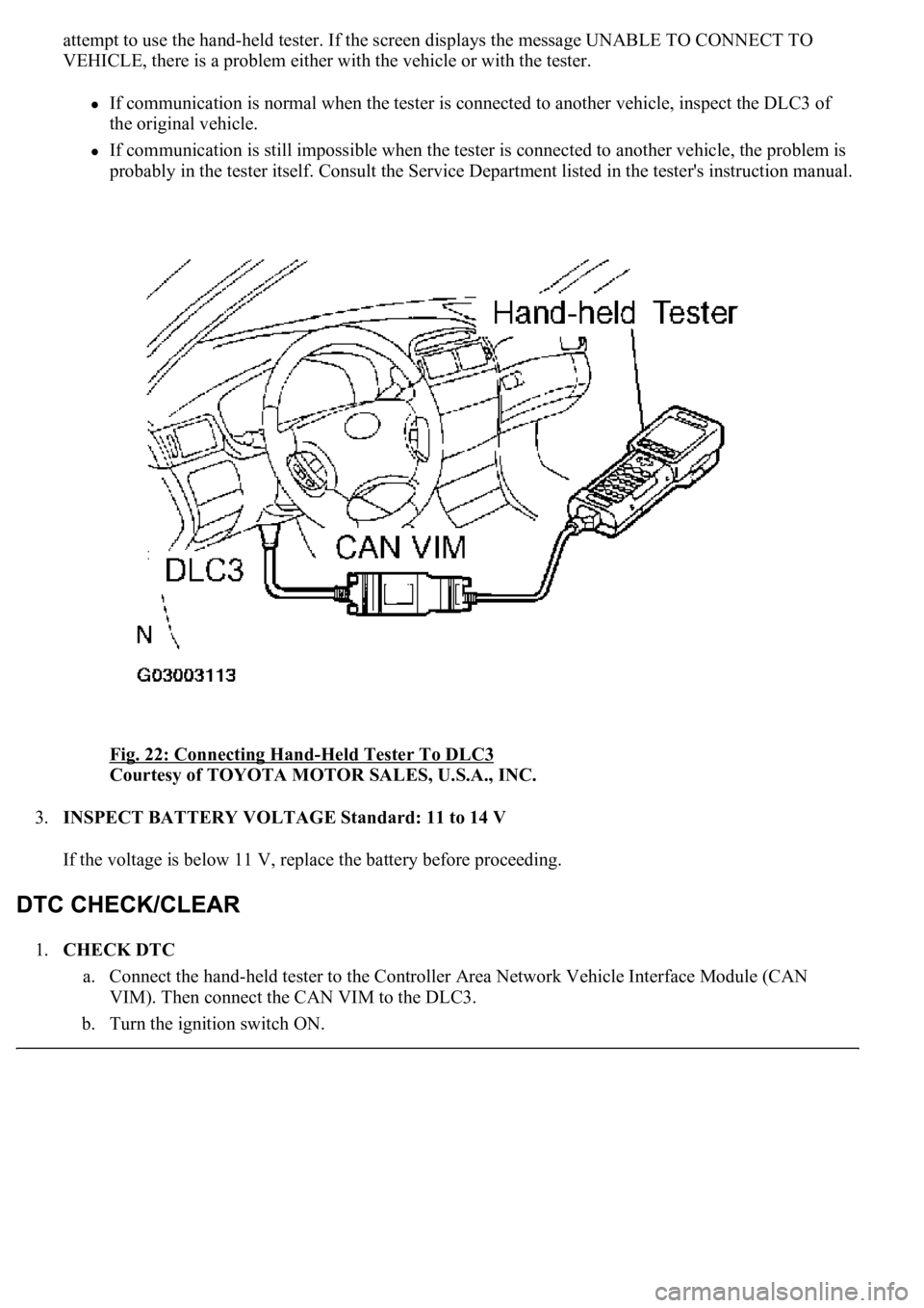
Fig. 22: Connecting Hand
-Held Tester To DLC3
Courtesy of TOYOTA MOTOR SALES, U.S.A., INC.
3.INSPECT BATTERY VOLTAGE Standard: 11 to 14 V
If the voltage is below 11 V, replace the battery before proceeding.
1.CHECK DTC
a. Connect the hand-held tester to the Controller Area Network Vehicle Interface Module (CAN
VIM). Then connect the CAN VIM to the DLC3.
b. Turn the ignition switch ON.
Page 3252 of 4500
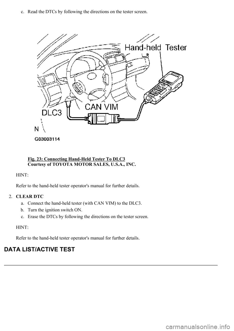
c. Read the DTCs by following the directions on the tester screen.
Fig. 23: Connecting Hand
-Held Tester To DLC3
Courtesy of TOYOTA MOTOR SALES, U.S.A., INC.
HINT:
Refer to the hand-held tester operator's manual for further details.
2.CLEAR DTC
a. Connect the hand-held tester (with CAN VIM) to the DLC3.
b. Turn the ignition switch ON.
c. Erase the DTCs by following the directions on the tester screen.
HINT:
Refer to the hand-held tester operator's manual for further details.
Page 3253 of 4500
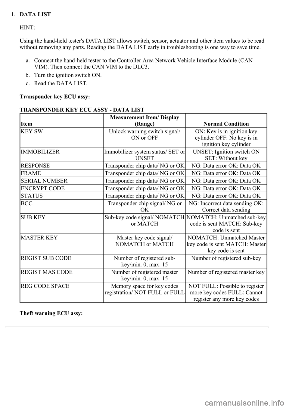
1.DATA LIST
HINT:
Using the hand-held tester's DATA LIST allows switch, sensor, actuator and other item values to be read
without removing any parts. Reading the DATA LIST early in troubleshooting is one way to save time.
a. Connect the hand-held tester to the Controller Area Network Vehicle Interface Module (CAN
VIM). Then connect the CAN VIM to the DLC3.
b. Turn the ignition switch ON.
c. Read the DATA LIST.
Transponder key ECU assy:
TRANSPONDER KEY ECU ASSY - DATA LIST
Theft warning ECU assy:
Item
Measurement Item/ Display
(Range)
Normal Condition
KEY SWUnlock warning switch signal/
ON or OFFON: Key is in ignition key
cylinder OFF: No key is in
ignition key cylinder
IMMOBILIZERImmobilizer system status/ SET or
UNSETUNSET: Ignition switch ON
SET: Without key
RESPONSETransponder chip data/ NG or OKNG: Data error OK: Data OK
FRAMETransponder chip data/ NG or OKNG: Data error OK: Data OK
SERIAL NUMBERTransponder chip data/ NG or OKNG: Data error OK: Data OK
ENCRYPT CODETransponder chip data/ NG or OKNG: Data error OK: Data OK
STATUSTransponder chip data/ NG or OKNG: Data error OK: Data OK
BCCTransponder chip signal/ NG or
OKNG: Incorrect data sending OK:
Correct data sending
SUB KEYSub-key code signal/ NOMATCH
or MATCHNOMATCH: Unmatched sub-key
code is sent MATCH: Sub-key
code is sent
MASTER KEYMaster key code signal/
NOMATCH or MATCHNOMATCH: Unmatched Master
key code is sent MATCH: Master
key code is sent
REGIST SUB CODENumber of registered sub-
key/min. 0, max. 15Number of registered sub-key
REGIST MAS CODENumber of registered master
key/min. 0, max. 15Number of registered master key
REG CODE SPACEMemory space for key codes
registration/ NOT FULL or FULLNOT FULL: Possible to register
more key codes FULL: Cannot
register any more key codes
Page 3254 of 4500
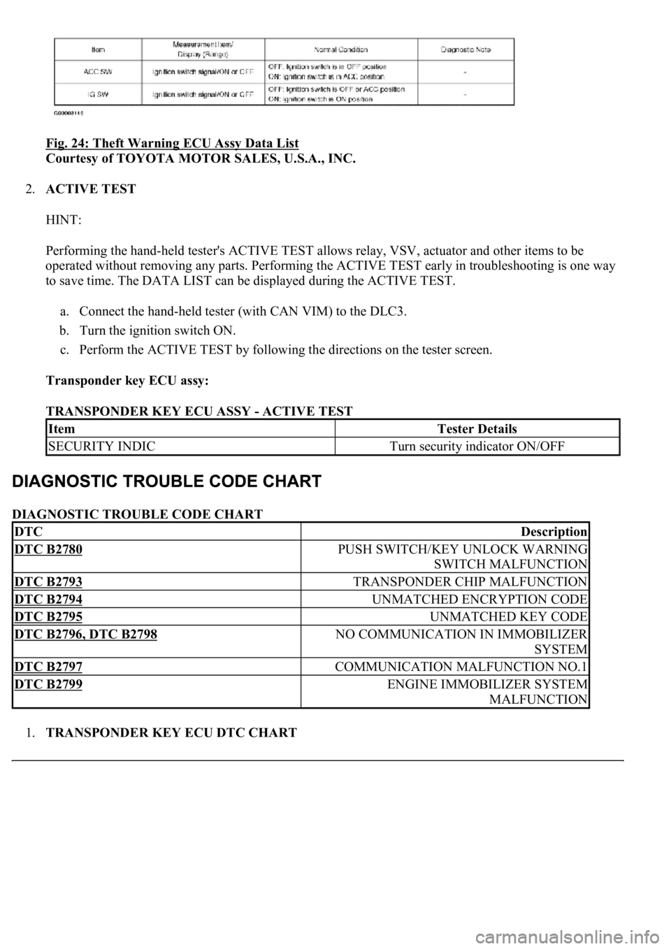
Fig. 24: Theft Warning ECU Assy Data List
Courtesy of TOYOTA MOTOR SALES, U.S.A., INC.
2.ACTIVE TEST
HINT:
Performing the hand-held tester's ACTIVE TEST allows relay, VSV, actuator and other items to be
operated without removing any parts. Performing the ACTIVE TEST early in troubleshooting is one way
to save time. The DATA LIST can be displayed during the ACTIVE TEST.
a. Connect the hand-held tester (with CAN VIM) to the DLC3.
b. Turn the ignition switch ON.
c. Perform the ACTIVE TEST by following the directions on the tester screen.
Transponder key ECU assy:
TRANSPONDER KEY ECU ASSY - ACTIVE TEST
DIAGNOSTIC TROUBLE CODE CHART
1.TRANSPONDER KEY ECU DTC CHART
ItemTester Details
SECURITY INDICTurn security indicator ON/OFF
DTCDescription
DTC B2780PUSH SWITCH/KEY UNLOCK WARNING
SWITCH MALFUNCTION
DTC B2793TRANSPONDER CHIP MALFUNCTION
DTC B2794UNMATCHED ENCRYPTION CODE
DTC B2795UNMATCHED KEY CODE
DTC B2796, DTC B2798NO COMMUNICATION IN IMMOBILIZER
SYSTEM
DTC B2797COMMUNICATION MALFUNCTION NO.1
DTC B2799ENGINE IMMOBILIZER SYSTEM
MALFUNCTION
Page 3255 of 4500
Fig. 25: Transponder Key ECU DTC Chart
Courtesy of TOYOTA MOTOR SALES, U.S.A., INC.
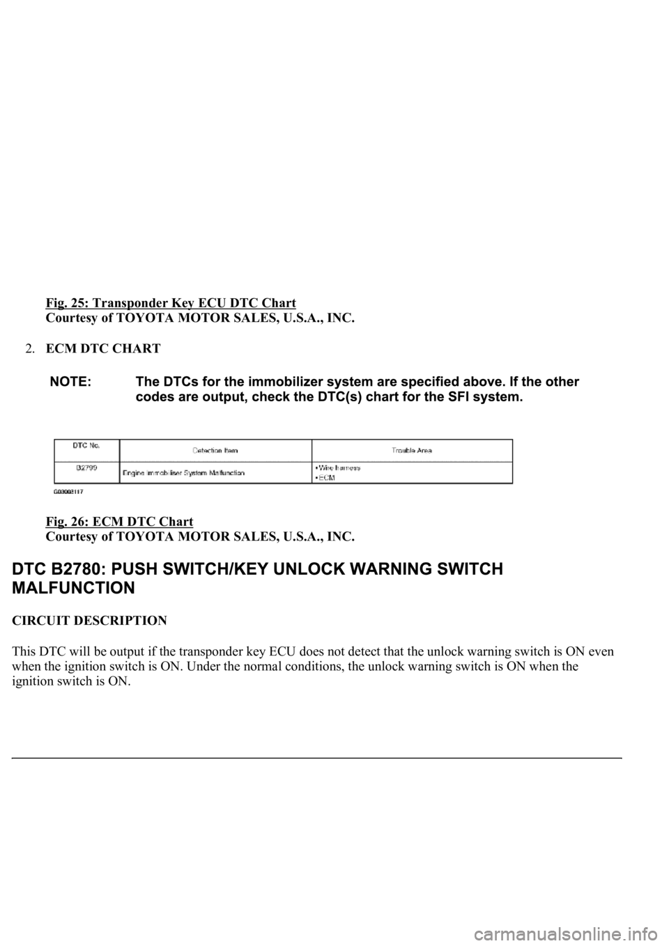
2.ECM DTC CHART
Fig. 26: ECM DTC Chart
Courtesy of TOYOTA MOTOR SALES, U.S.A., INC.
CIRCUIT DESCRIPTION
This DTC will be output if the transponder key ECU does not detect that the unlock warning switch is ON even
when the ignition switch is ON. Under the normal conditions, the unlock warning switch is ON when the
i
gnition switch is ON.
Page 3256 of 4500
Fig. 27: DTC Reference Chart
Courtesy of TOYOTA MOTOR SALES, U.S.A., INC.
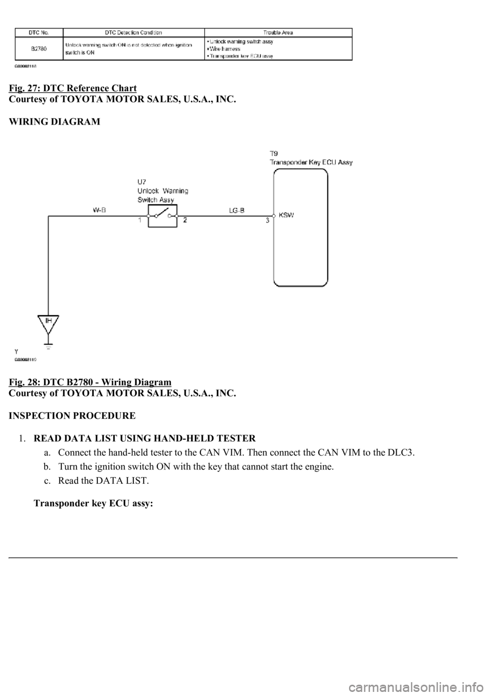
WIRING DIAGRAM
Fig. 28: DTC B2780
- Wiring Diagram
Courtesy of TOYOTA MOTOR SALES, U.S.A., INC.
INSPECTION PROCEDURE
1.READ DATA LIST USING HAND-HELD TESTER
a. Connect the hand-held tester to the CAN VIM. Then connect the CAN VIM to the DLC3.
b. Turn the ignition switch ON with the key that cannot start the engine.
c. Read the DATA LIST.
Transponder key ECU assy:
Page 3257 of 4500
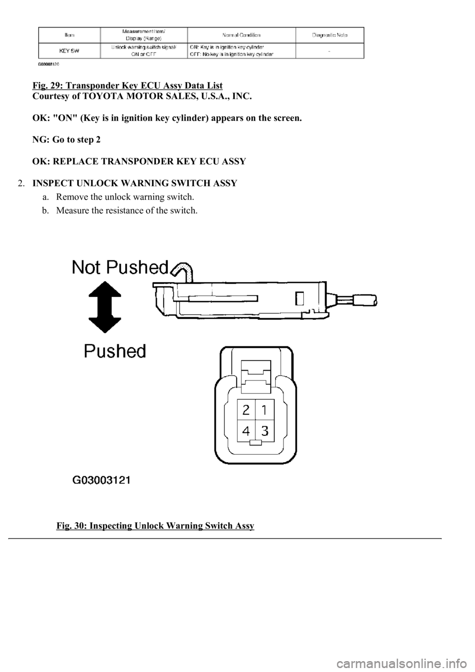
Fig. 29: Transponder Key ECU Assy Data List
Courtesy of TOYOTA MOTOR SALES, U.S.A., INC.
OK: "ON" (Key is in ignition key cylinder) appears on the screen.
NG: Go to step 2
OK: REPLACE TRANSPONDER KEY ECU ASSY
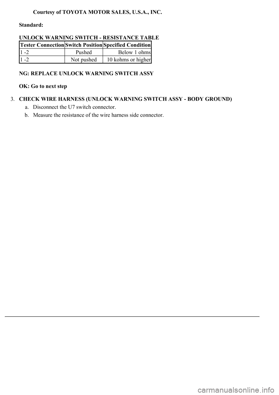
2.INSPECT UNLOCK WARNING SWITCH ASSY
a. Remove the unlock warning switch.
b. Measure the resistance of the switch.
Fig. 30: Inspecting Unlock Warning Switch Assy
Page 3258 of 4500
Courtesy of TOYOTA MOTOR SALES, U.S.A., INC.
Standard:
UNLOCK WARNING SWITCH - RESISTANCE TABLE
NG: REPLACE UNLOCK WARNING SWITCH ASSY
OK: Go to next step
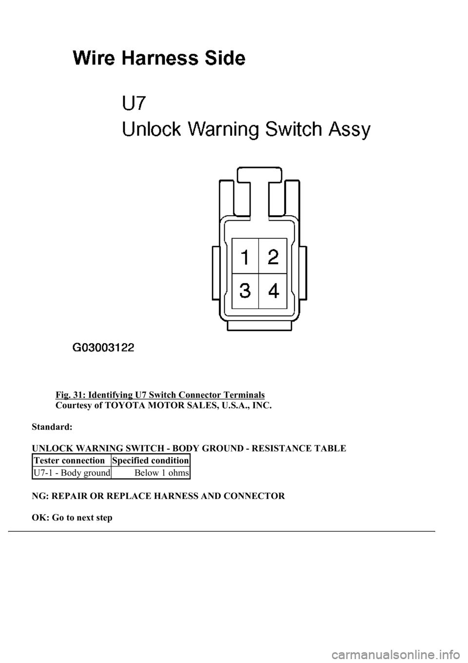
3.CHECK WIRE HARNESS (UNLOCK WARNING SWITCH ASSY - BODY GROUND)
a. Disconnect the U7 switch connector.
b. Measure the resistance of the wire harness side connector.
Tester ConnectionSwitch PositionSpecified Condition
1 -2PushedBelow 1 ohms
1 -2Not pushed10 kohms or higher
Page 3259 of 4500
Fig. 31: Identifying U7 Switch Connector Terminals
Courtesy of TOYOTA MOTOR SALES, U.S.A., INC.
Standard:
UNLOCK WARNING SWITCH - BODY GROUND - RESISTANCE TABLE
NG: REPAIR OR REPLACE HARNESS AND CONNECTOR
OK: Go to next step
Tester connectionSpecified condition
U7-1 - Body groundBelow 1 ohms
Page 3260 of 4500
4.CHECK WIRE HARNESS (TRANSPONDER KEY ECU ASSY - UNLOCK WARNING SWITCH
ASSY)
a. Disconnect the T9 ECU connector.
b. Disconnect the U7 switch connector.
c. Measure the resistance of the wire harness side connectors.
Trending: weight, battery replacement, Identifying compressor condition, horn, navigation update, wipers, seat adjustment
