LEXUS LS430 2003 Factory Repair Manual
Manufacturer: LEXUS, Model Year: 2003,
Model line: LS430,
Model: LEXUS LS430 2003
Pages: 4500, PDF Size: 87.45 MB
LEXUS LS430 2003 Factory Repair Manual
LS430 2003
LEXUS
LEXUS
https://www.carmanualsonline.info/img/36/57050/w960_57050-0.png
LEXUS LS430 2003 Factory Repair Manual
Trending: fuel consumption, fuel filter, c1725, oil temperature, warning light, service reset, timing belt
Page 3271 of 4500
NG: FIND CAUSE OF NOISE AND REMOVE IT
OK: Go to next step
4.CHECK WIRE HARNESS (TRANSPONDER KEY ECU ASSY - TRANSPONDER KEY
AMPLIFIER)
a. Disconnect the T9 ECU connector.
b. Disconnect the T8 amplifier connector.
c. Measure the resistance of the wire harness side connectors.
Tool Setting10 V/DIV.,20 ms/DIV.
ConditionIgnition switch OFF --> ON
Page 3272 of 4500
Page 3273 of 4500
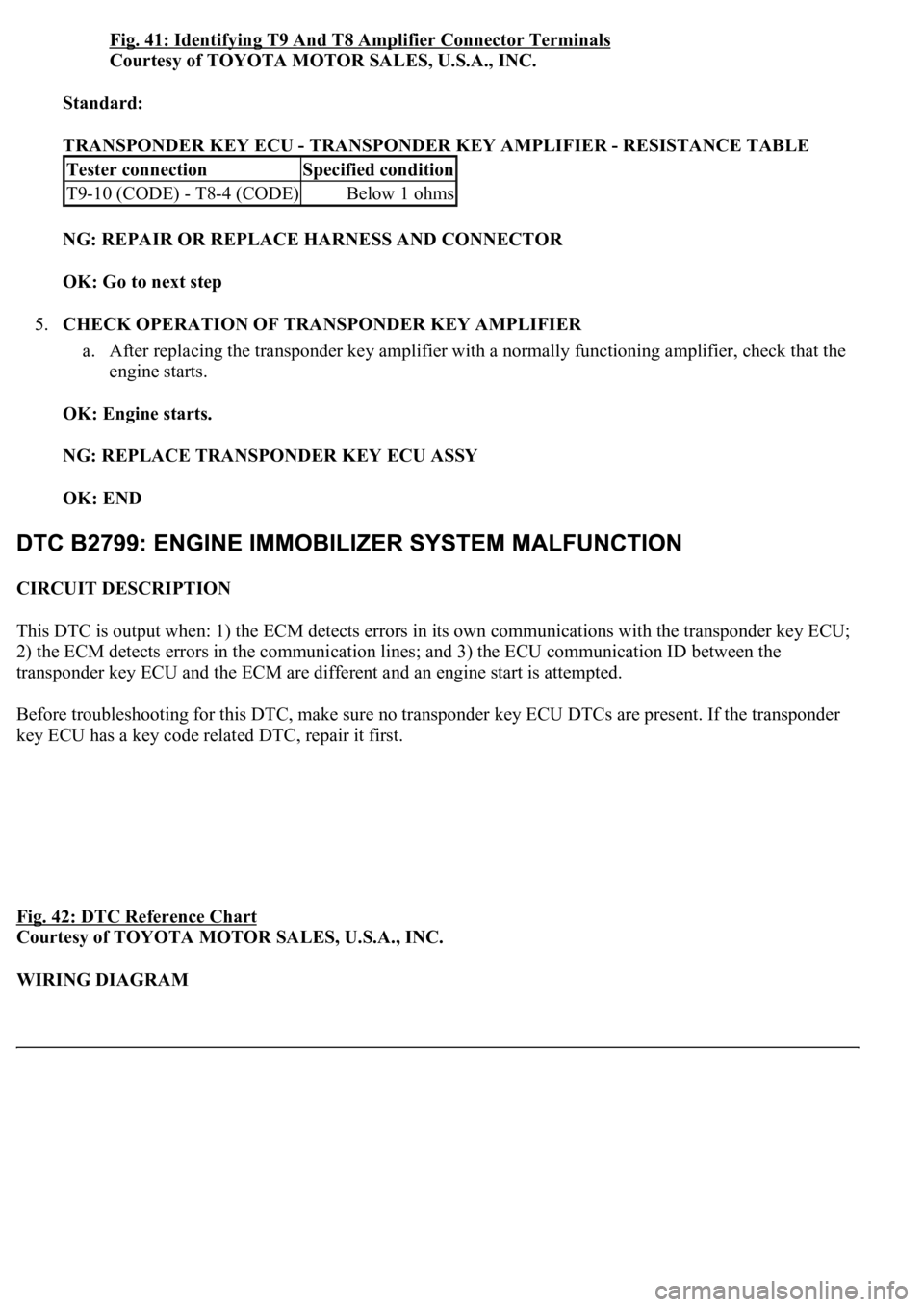
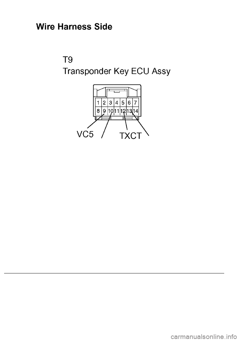
Fig. 41: Identifying T9 And T8 Amplifier Connector Terminals
Courtesy of TOYOTA MOTOR SALES, U.S.A., INC.
Standard:
TRANSPONDER KEY ECU - TRANSPONDER KEY AMPLIFIER - RESISTANCE TABLE
NG: REPAIR OR REPLACE HARNESS AND CONNECTOR
OK: Go to next step
5.CHECK OPERATION OF TRANSPONDER KEY AMPLIFIER
a. After replacing the transponder key amplifier with a normally functioning amplifier, check that the
engine starts.
OK: Engine starts.
NG: REPLACE TRANSPONDER KEY ECU ASSY
OK: END
CIRCUIT DESCRIPTION
This DTC is output when: 1) the ECM detects errors in its own communications with the transponder key ECU;
2) the ECM detects errors in the communication lines; and 3) the ECU communication ID between the
transponder key ECU and the ECM are different and an engine start is attempted.
Before troubleshooting for this DTC, make sure no transponder key ECU DTCs are present. If the transponder
key ECU has a key code related DTC, repair it first.
Fig. 42: DTC Reference Chart
Courtesy of TOYOTA MOTOR SALES, U.S.A., INC.
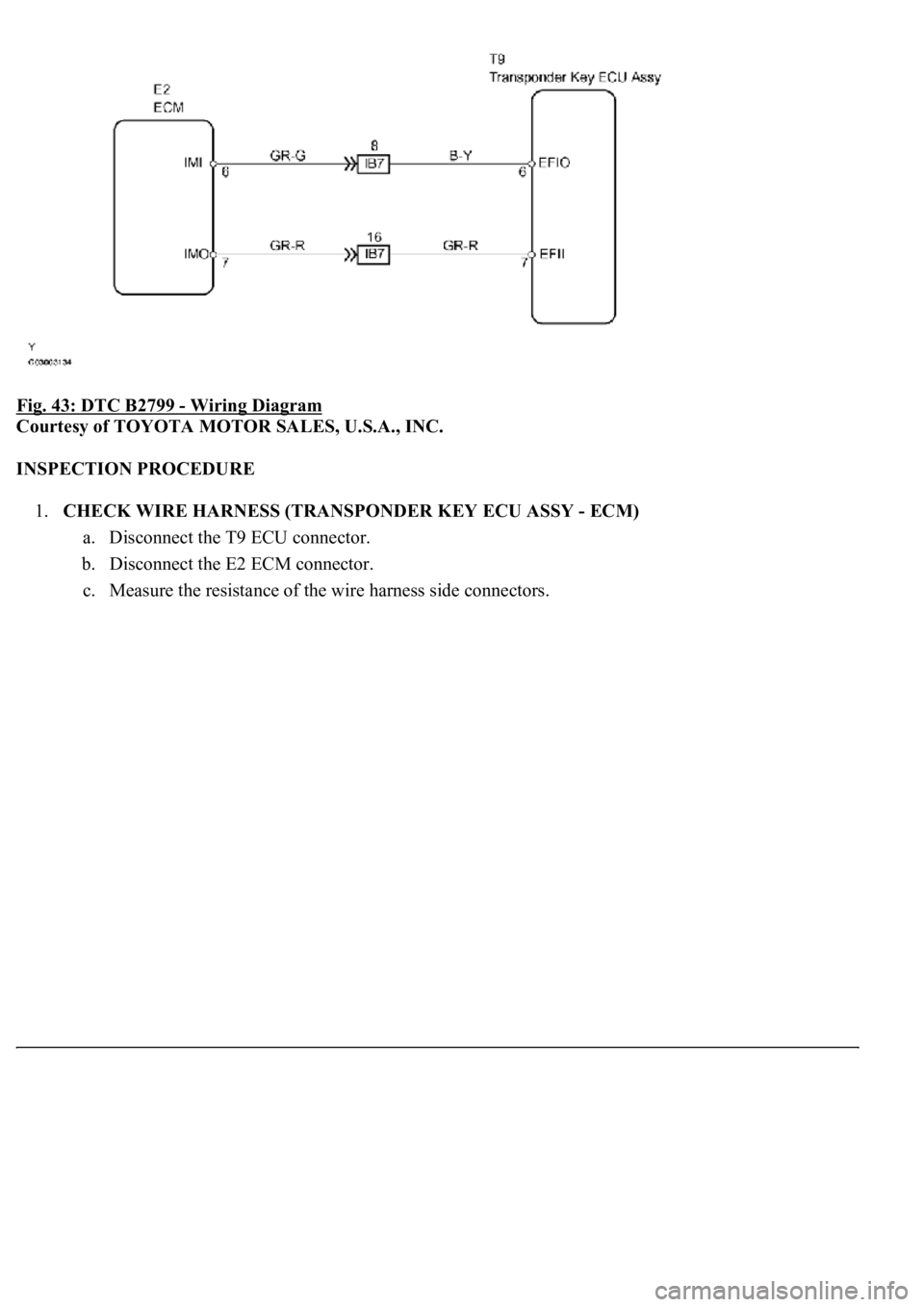
WIRING DIAGRAM
Tester connectionSpecified condition
T9-10 (CODE) - T8-4 (CODE)Below 1 ohms
Page 3274 of 4500
Fig. 43: DTC B2799 - Wiring Diagram
Courtesy of TOYOTA MOTOR SALES, U.S.A., INC.
INSPECTION PROCEDURE
1.CHECK WIRE HARNESS (TRANSPONDER KEY ECU ASSY - ECM)
a. Disconnect the T9 ECU connector.
b. Disconnect the E2 ECM connector.
c. Measure the resistance of the wire harness side connectors.
Page 3275 of 4500
Page 3276 of 4500
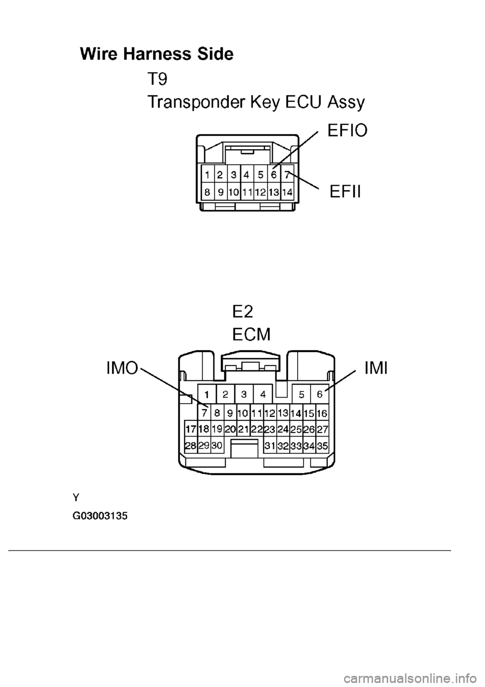
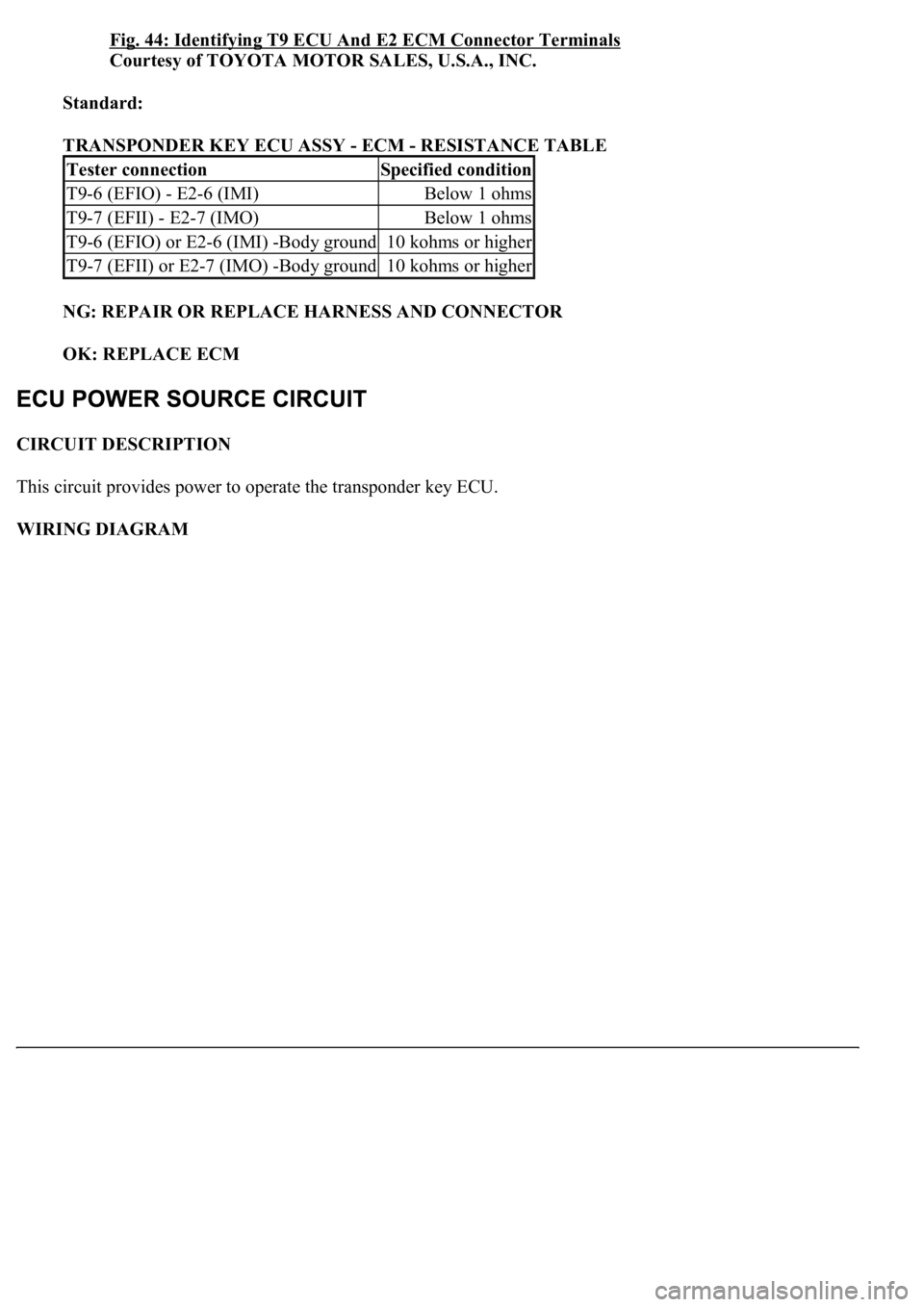
Fig. 44: Identifying T9 ECU And E2 ECM Connector Terminals
Courtesy of TOYOTA MOTOR SALES, U.S.A., INC.
Standard:
TRANSPONDER KEY ECU ASSY - ECM - RESISTANCE TABLE
NG: REPAIR OR REPLACE HARNESS AND CONNECTOR
OK: REPLACE ECM
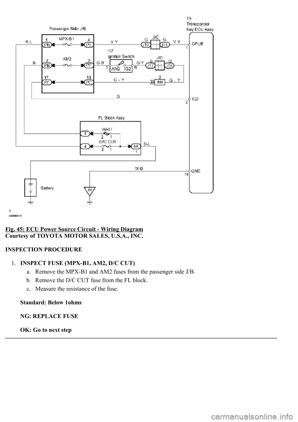
CIRCUIT DESCRIPTION
This circuit provides power to operate the transponder key ECU.
WIRING DIAGRAM
Tester connectionSpecified condition
T9-6 (EFIO) - E2-6 (IMI)Below 1 ohms
T9-7 (EFII) - E2-7 (IMO)Below 1 ohms
T9-6 (EFIO) or E2-6 (IMI) -Body ground10 kohms or higher
T9-7 (EFII) or E2-7 (IMO) -Body ground10 kohms or higher
Page 3277 of 4500
Fig. 45: ECU Power Source Circuit - Wiring Diagram
Courtesy of TOYOTA MOTOR SALES, U.S.A., INC.
INSPECTION PROCEDURE
1.INSPECT FUSE (MPX-B1, AM2, D/C CUT)
a. Remove the MPX-B1 and AM2 fuses from the passenger side J/B.
b. Remove the D/C CUT fuse from the FL block.
c. Measure the resistance of the fuse.
Standard: Below 1ohms
NG: REPLACE FUSE
OK: Go to next step
Page 3278 of 4500
2.CHECK WIRE HARNESS (TRANSPONDER KEY ECU ASSY - BATTERY AND BODY
GROUND)
a. Disconnect the T9 ECU connector.
b. Measure the resistance and voltage of the wire harness side connector.
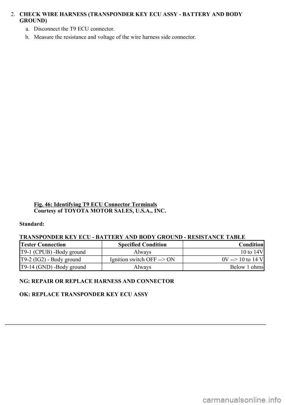
Fig. 46: Identifying T9 ECU Connector Terminals
Courtesy of TOYOTA MOTOR SALES, U.S.A., INC.
Standard:
TRANSPONDER KEY ECU - BATTERY AND BODY GROUND - RESISTANCE TABLE
NG: REPAIR OR REPLACE HARNESS AND CONNECTOR
OK: REPLACE TRANSPONDER KEY ECU ASSY
Tester ConnectionSpecified ConditionCondition
T9-1 (CPUB) -Body groundAlways10 to 14V
T9-2 (IG2) - Body groundIgnition switch OFF --> ON0V --> 10 to 14 V
T9-14 (GND) -Body groundAlwaysBelow 1 ohms
Page 3279 of 4500
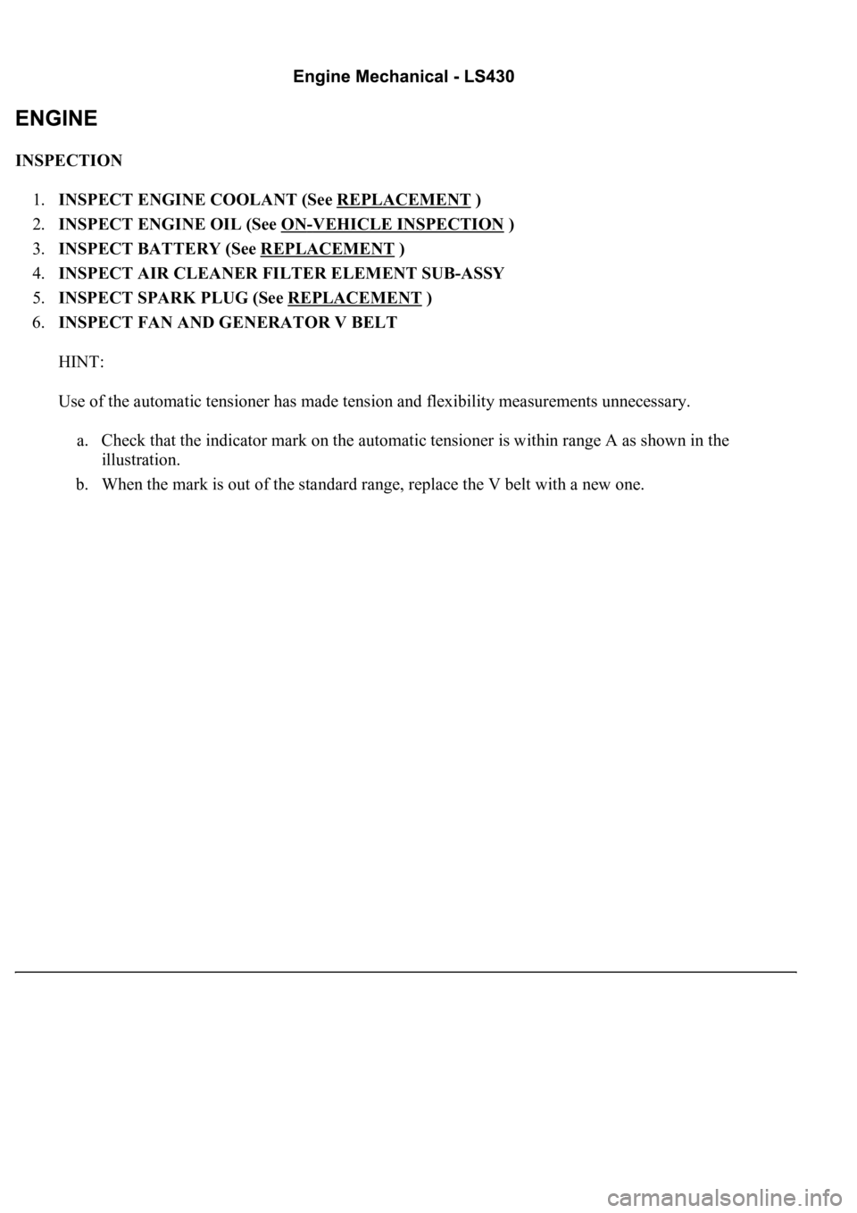
INSPECTION
1.INSPECT ENGINE COOLANT (See REPLACEMENT
)
2.INSPECT ENGINE OIL (See ON
-VEHICLE INSPECTION )
3.INSPECT BATTERY (See REPLACEMENT
)
4.INSPECT AIR CLEANER FILTER ELEMENT SUB-ASSY
5.INSPECT SPARK PLUG (See REPLACEMENT
)
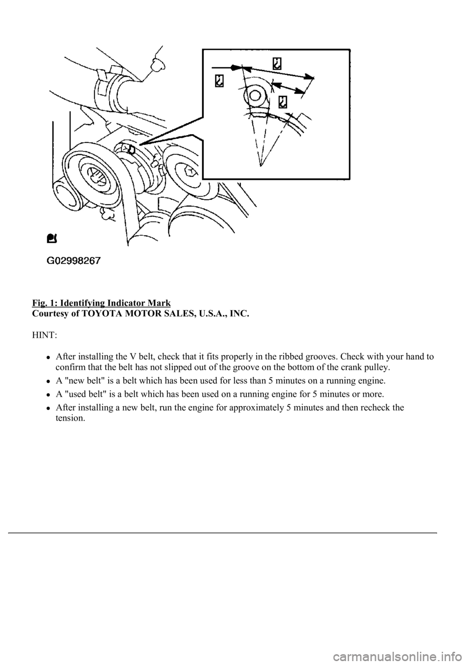
6.INSPECT FAN AND GENERATOR V BELT
HINT:
Use of the automatic tensioner has made tension and flexibility measurements unnecessary.
a. Check that the indicator mark on the automatic tensioner is within range A as shown in the
illustration.
b. When the mark is out of the standard range, replace the V belt with a new one.
Page 3280 of 4500
Fig. 1: Identifying Indicator Mark
Courtesy of TOYOTA MOTOR SALES, U.S.A., INC.
HINT:
After installing the V belt, check that it fits properly in the ribbed grooves. Check with your hand to
confirm that the belt has not slipped out of the groove on the bottom of the crank pulley.
A "new belt" is a belt which has been used for less than 5 minutes on a running engine.
A "used belt" is a belt which has been used on a running engine for 5 minutes or more.
After installing a new belt, run the engine for approximately 5 minutes and then recheck the
tension.
Trending: airbag off, wiring diagram, USB, B2620, seat memory, pcv, Expansion Valve
