LEXUS LS430 2003 Factory Repair Manual
Manufacturer: LEXUS, Model Year: 2003,
Model line: LS430,
Model: LEXUS LS430 2003
Pages: 4500, PDF Size: 87.45 MB
LEXUS LS430 2003 Factory Repair Manual
LS430 2003
LEXUS
LEXUS
https://www.carmanualsonline.info/img/36/57050/w960_57050-0.png
LEXUS LS430 2003 Factory Repair Manual
Trending: Ecm, oil level, center console, catalytic converter, headrest, trailer, electronic modulated
Page 3331 of 4500
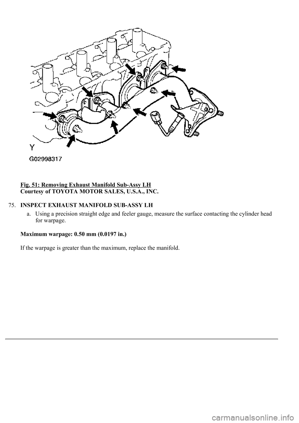
Fig. 51: Removing Exhaust Manifold Sub-Assy LH
Courtesy of TOYOTA MOTOR SALES, U.S.A., INC.
75.INSPECT EXHAUST MANIFOLD SUB-ASSY LH
a. Using a precision straight edge and feeler gauge, measure the surface contacting the cylinder head
for warpage.
Maximum warpage: 0.50 mm (0.0197 in.)
If the warpa
ge is greater than the maximum, replace the manifold.
Page 3332 of 4500
Fig. 52: Measuring Surface
Courtesy of TOYOTA MOTOR SALES, U.S.A., INC.
76.REMOVE WIRING HARNESS HEAT INSULATOR NO.2
77.REMOVE ENGINE MOUNTING BRACKET FRONT NO.1 RH
78.REMOVE ENGINE MOUNTING BRACKET FRONT NO.1 LH
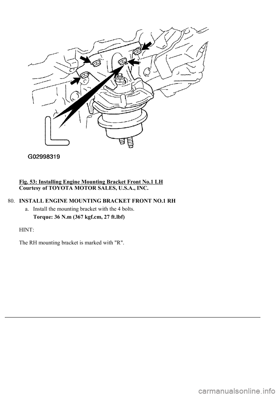
79.INSTALL ENGINE MOUNTING BRACKET FRONT NO.1 LH
a. Install the mounting bracket with the 4 bolts.
Torque: 36 N.m (367 kgf.cm, 27 ft.lbf)
HINT:
The LH mountin
g bracket is marked with "L".
Page 3333 of 4500
Fig. 53: Installing Engine Mounting Bracket Front No.1 LH
Courtesy of TOYOTA MOTOR SALES, U.S.A., INC.
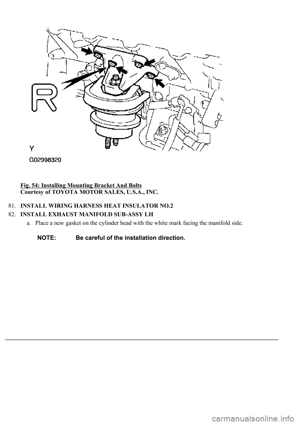
80.INSTALL ENGINE MOUNTING BRACKET FRONT NO.1 RH
a. Install the mounting bracket with the 4 bolts.
Torque: 36 N.m (367 kgf.cm, 27 ft.lbf)
HINT:
The RH mountin
g bracket is marked with "R".
Page 3334 of 4500
Fig. 54: Installing Mounting Bracket And Bolts
Courtesy of TOYOTA MOTOR SALES, U.S.A., INC.
81.INSTALL WIRING HARNESS HEAT INSULATOR NO.2
82.INSTALL EXHAUST MANIFOLD SUB-ASSY LH
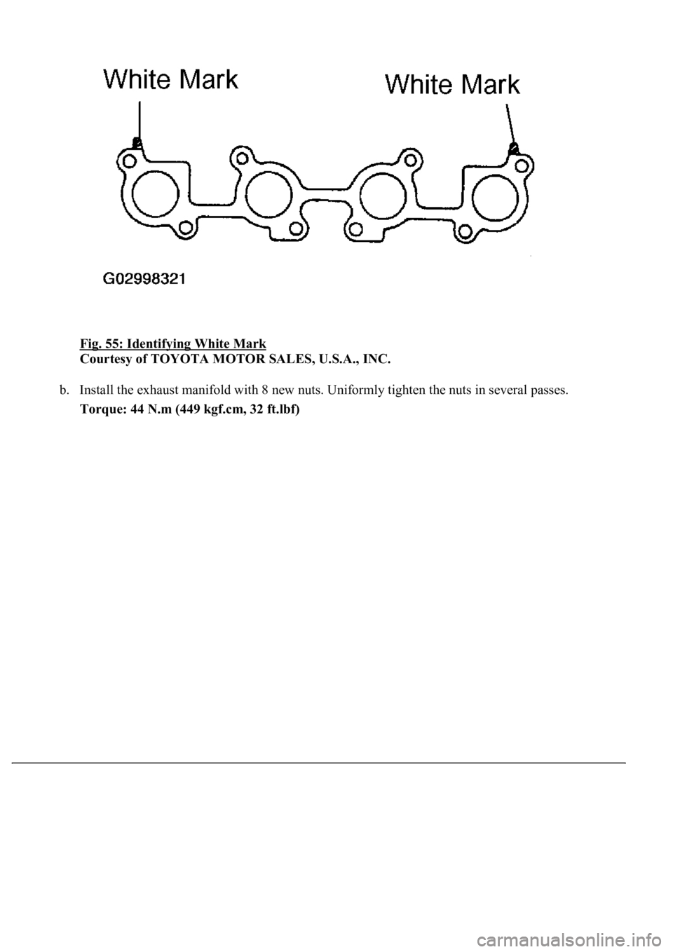
a. Place a new gasket on the cylinder head with the white mark facing the manifold side.
Page 3335 of 4500
Fig. 55: Identifying White Mark
Courtesy of TOYOTA MOTOR SALES, U.S.A., INC.
b. Install the exhaust manifold with 8 new nuts. Uniformly tighten the nuts in several passes.
Torque: 44 N.m (449 kgf.cm, 32 ft.lbf)
Page 3336 of 4500
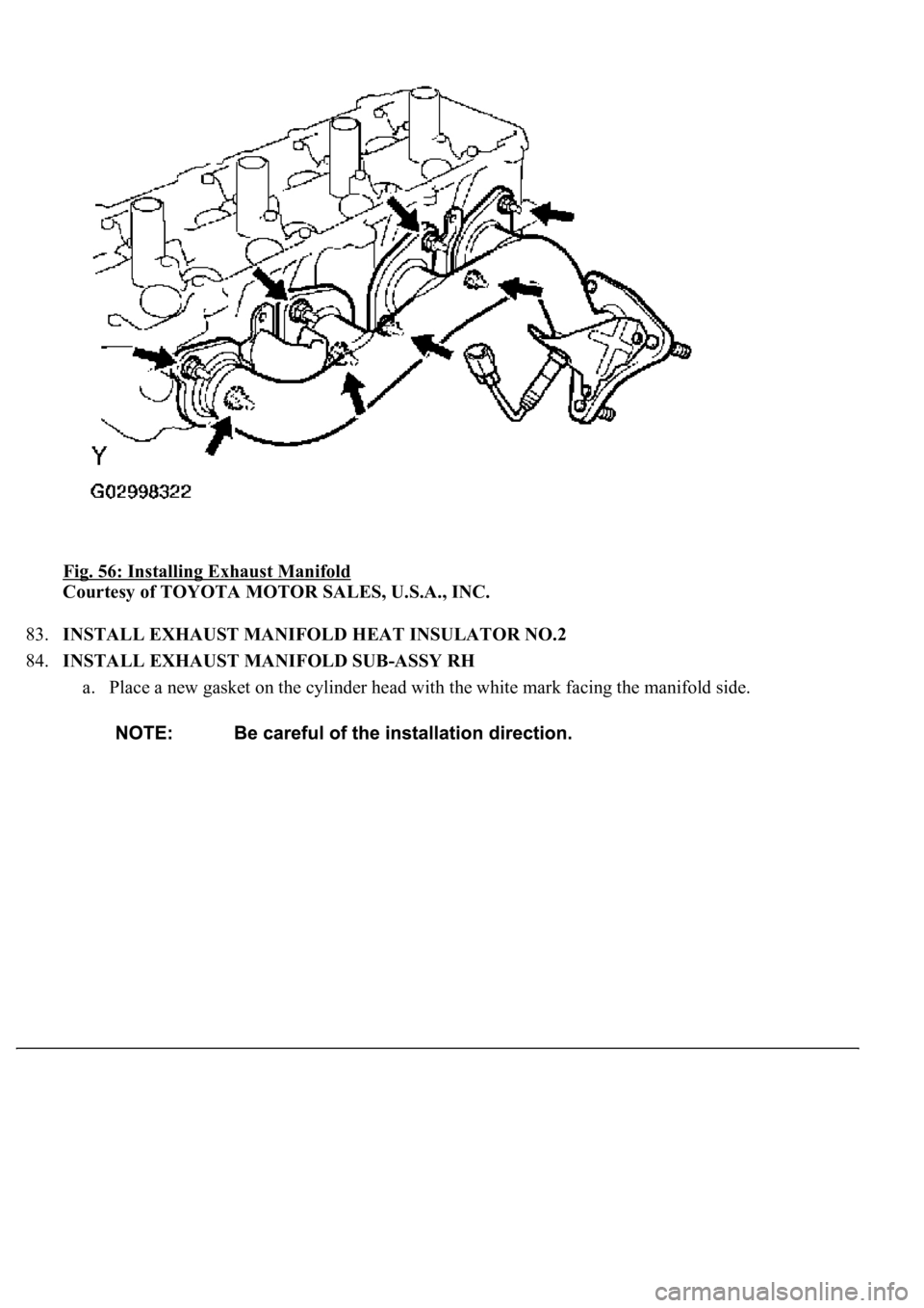
Fig. 56: Installing Exhaust Manifold
Courtesy of TOYOTA MOTOR SALES, U.S.A., INC.
83.INSTALL EXHAUST MANIFOLD HEAT INSULATOR NO.2
84.INSTALL EXHAUST MANIFOLD SUB-ASSY RH
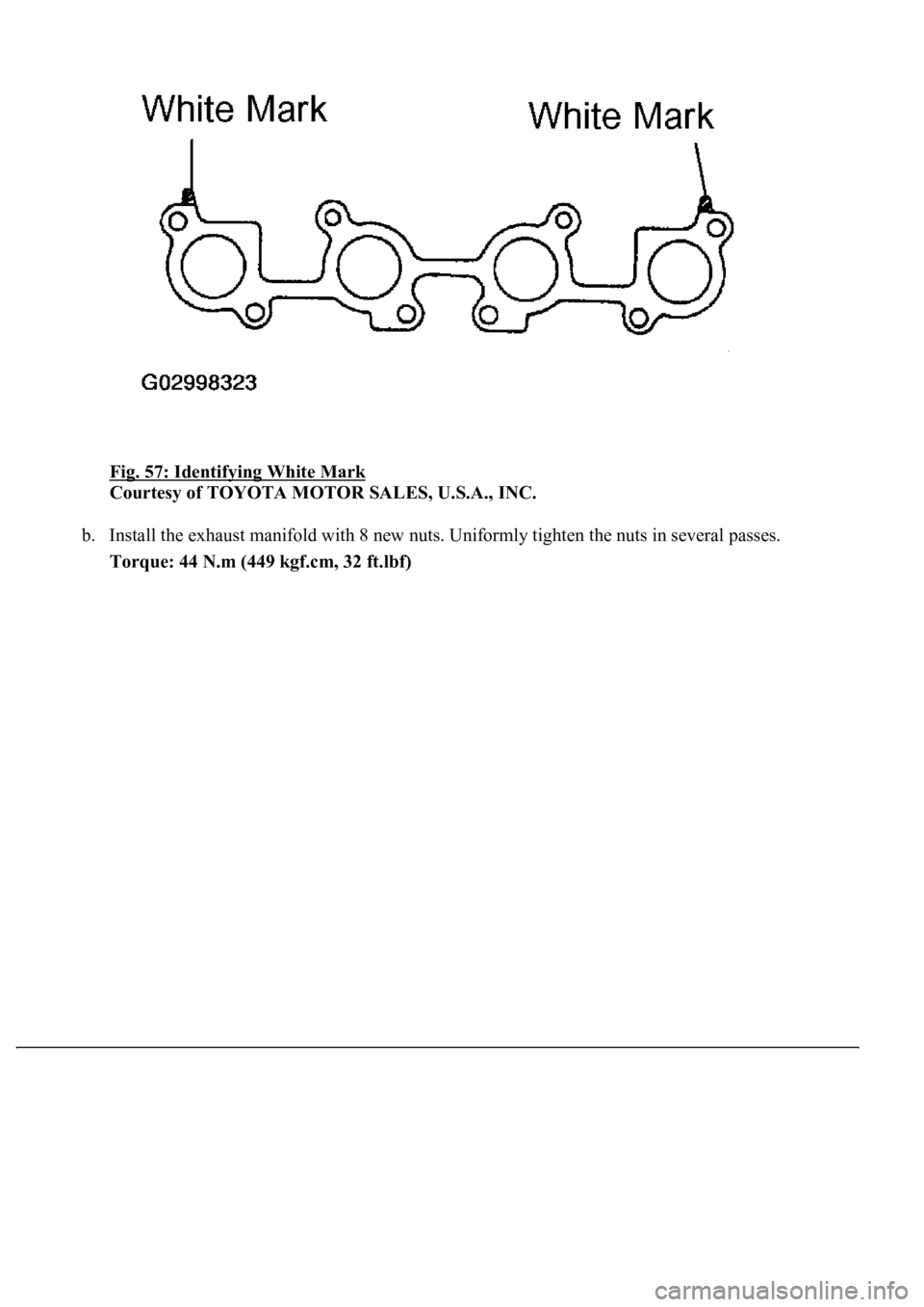
a. Place a new gasket on the cylinder head with the white mark facing the manifold side.
Page 3337 of 4500
Fig. 57: Identifying White Mark
Courtesy of TOYOTA MOTOR SALES, U.S.A., INC.
b. Install the exhaust manifold with 8 new nuts. Uniformly tighten the nuts in several passes.
Torque: 44 N.m (449 kgf.cm, 32 ft.lbf)
Page 3338 of 4500
Fig. 58: Installing Exhaust Manifold
Courtesy of TOYOTA MOTOR SALES, U.S.A., INC.
85.INSTALL EXHAUST MANIFOLD HEAT INSULATOR NO.1
86.INSTALL ENGINE OIL LEVEL SENSOR
87.INSTALL CRANKSHAFT POSITION SENSOR (See REPLACEMENT
)
88.INSTALL OIL FILTER BRACKET SUB-ASSY
Torque: 18 N.m (184 kgf.cm, 13 ft.lbf)
89.INSTALL IGNITION COIL ASSY
Torque: 7.5 N.m (77 kgf.cm, 66 in.lbf)
90.INSTALL ENGINE HANGER NO.2
Torque: 37 N.m (377 kgf.cm, 27 ft.lbf)
91.INSTALL ENGINE HANGER NO. 1
Torque: 37 N.m (377 kgf.cm, 27 ft.lbf)
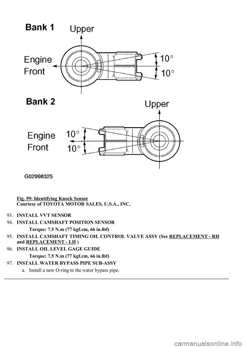
92.INSTALL KNOCK SENSOR
a. Install the 2 knock sensors with the 2 nuts, as shown in the illustration.
Torque: 20 N.m (204 kgf.cm, 15 ft.lbf)
b. Connect the 2 knock sensor connectors.
Page 3339 of 4500
Fig. 59: Identifying Knock Sensor
Courtesy of TOYOTA MOTOR SALES, U.S.A., INC.
93.INSTALL VVT SENSOR
94.INSTALL CAMSHAFT POSITION SENSOR
Torque: 7.5 N.m (77 kgf.cm, 66 in.lbf)
95.INSTALL CAMSHAFT TIMING OIL CONTROL VALVE ASSY (See REPLACEMENT
- RH
and REPLACEMENT
- LH )
96.INSTALL OIL LEVEL GAGE GUIDE
Torque: 7.5 N.m (77 kgf.cm, 66 in.lbf)
97.INSTALL WATER BYPASS PIPE SUB-ASSY
a. Install a new O-rin
g to the water bypass pipe.
Page 3340 of 4500
b. Apply soapy water to the O-ring.
c. Push in the water bypass pipe end into the pipe hole of the water pump.
d. Install the water bypass pipe with the bolt.
Torque: 18 N.m (184 kgf.cm, 13 ft.lbf)
e. Install the wire clamp to the bracket of the water bypass pipe.
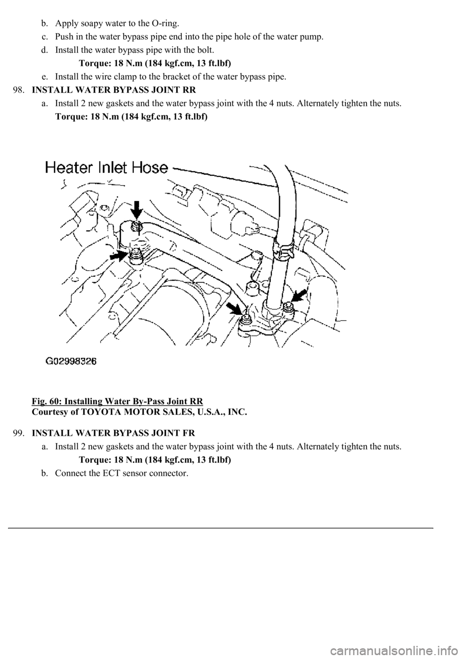
98.INSTALL WATER BYPASS JOINT RR
a. Install 2 new gaskets and the water bypass joint with the 4 nuts. Alternately tighten the nuts.
Torque: 18 N.m (184 kgf.cm, 13 ft.lbf)
Fig. 60: Installing Water By
-Pass Joint RR
Courtesy of TOYOTA MOTOR SALES, U.S.A., INC.
99.INSTALL WATER BYPASS JOINT FR
a. Install 2 new gaskets and the water bypass joint with the 4 nuts. Alternately tighten the nuts.
Torque: 18 N.m (184 kgf.cm, 13 ft.lbf)
b. Connect the ECT sensor connector.
Trending: evaporator removal, Rear control Arm, Door lock, height adjustment, Expansion Valve, wheel bolt torque, wipers
