LEXUS LS430 2003 Factory Repair Manual
Manufacturer: LEXUS, Model Year: 2003,
Model line: LS430,
Model: LEXUS LS430 2003
Pages: 4500, PDF Size: 87.45 MB
LEXUS LS430 2003 Factory Repair Manual
LS430 2003
LEXUS
LEXUS
https://www.carmanualsonline.info/img/36/57050/w960_57050-0.png
LEXUS LS430 2003 Factory Repair Manual
Trending: navigation system, trunk, stop start, check oil, warning, checking oil, seat adjustment
Page 3341 of 4500
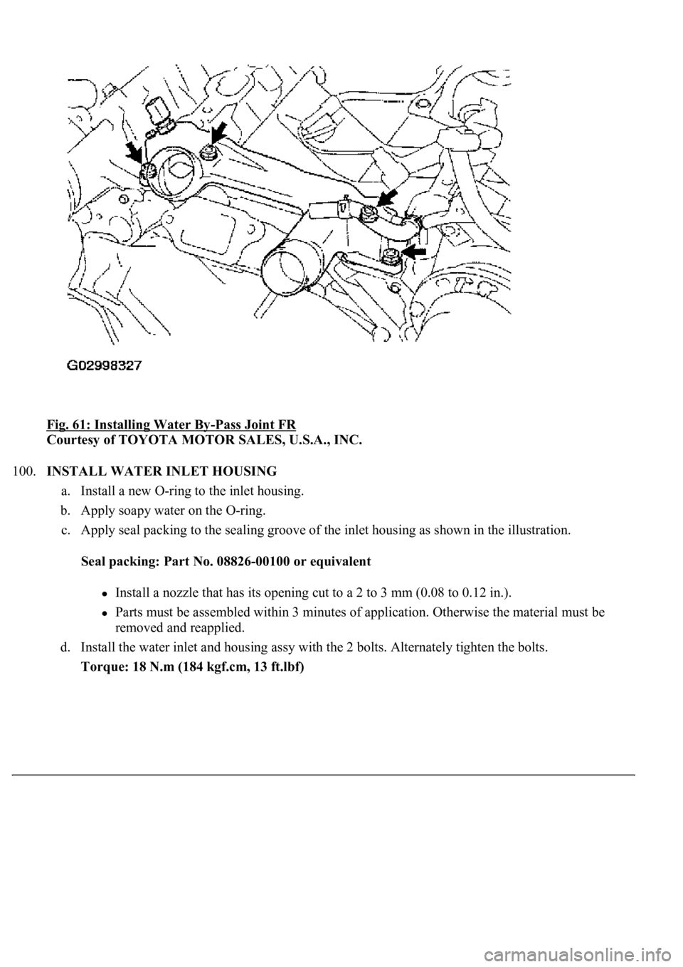
Fig. 61: Installing Water By-Pass Joint FR
Courtesy of TOYOTA MOTOR SALES, U.S.A., INC.
100.INSTALL WATER INLET HOUSING
a. Install a new O-ring to the inlet housing.
b. Apply soapy water on the O-ring.
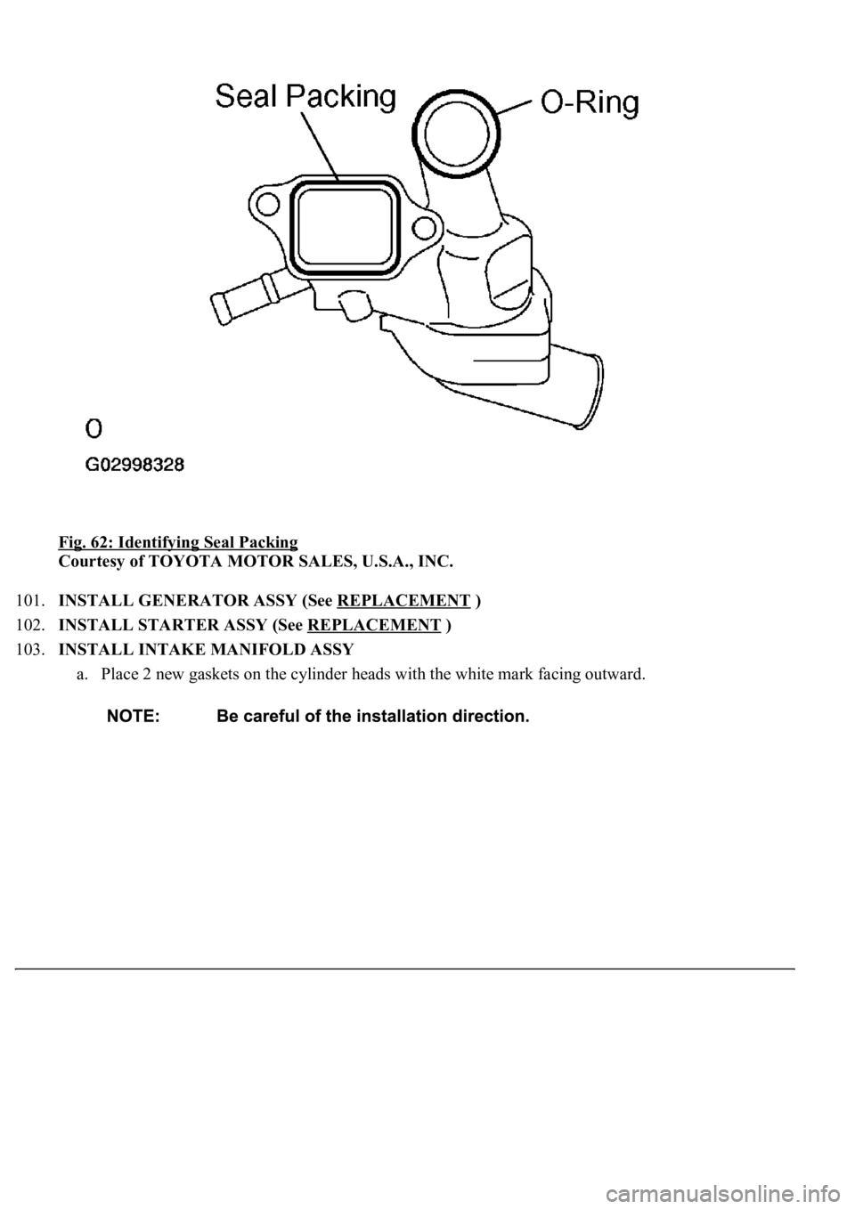
c. Apply seal packing to the sealing groove of the inlet housing as shown in the illustration.
Seal packing: Part No. 08826-00100 or equivalent
<002c0051005600570044004f004f00030044000300510052005d005d004f004800030057004b004400570003004b004400560003004c0057005600030052005300480051004c0051004a000300460058005700030057005200030044000300150003005700
52000300160003005000500003000b001300110013001b0003[to 0.12 in.).
Parts must be assembled within 3 minutes of application. Otherwise the material must be
removed and reapplied.
d. Install the water inlet and housing assy with the 2 bolts. Alternately tighten the bolts.
Torque: 18 N.m (184 kgf.cm, 13 ft.lbf)
Page 3342 of 4500
Fig. 62: Identifying Seal Packing
Courtesy of TOYOTA MOTOR SALES, U.S.A., INC.
101.INSTALL GENERATOR ASSY (See REPLACEMENT
)
102.INSTALL STARTER ASSY (See REPLACEMENT
)
103.INSTALL INTAKE MANIFOLD ASSY
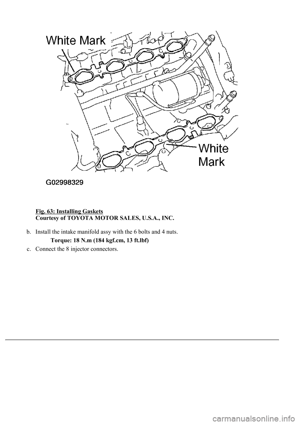
a. Place 2 new gaskets on the cylinder heads with the white mark facing outward.
Page 3343 of 4500
Fig. 63: Installing Gaskets
Courtesy of TOYOTA MOTOR SALES, U.S.A., INC.
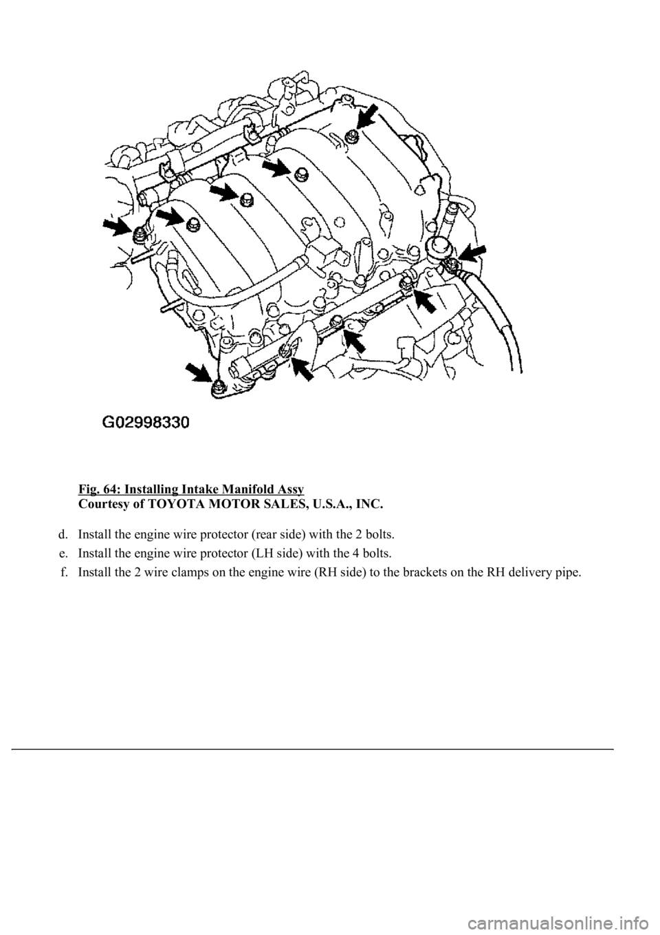
b. Install the intake manifold assy with the 6 bolts and 4 nuts.
Torque: 18 N.m (184 kgf.cm, 13 ft.lbf)
c. Connect the 8 in
jector connectors.
Page 3344 of 4500
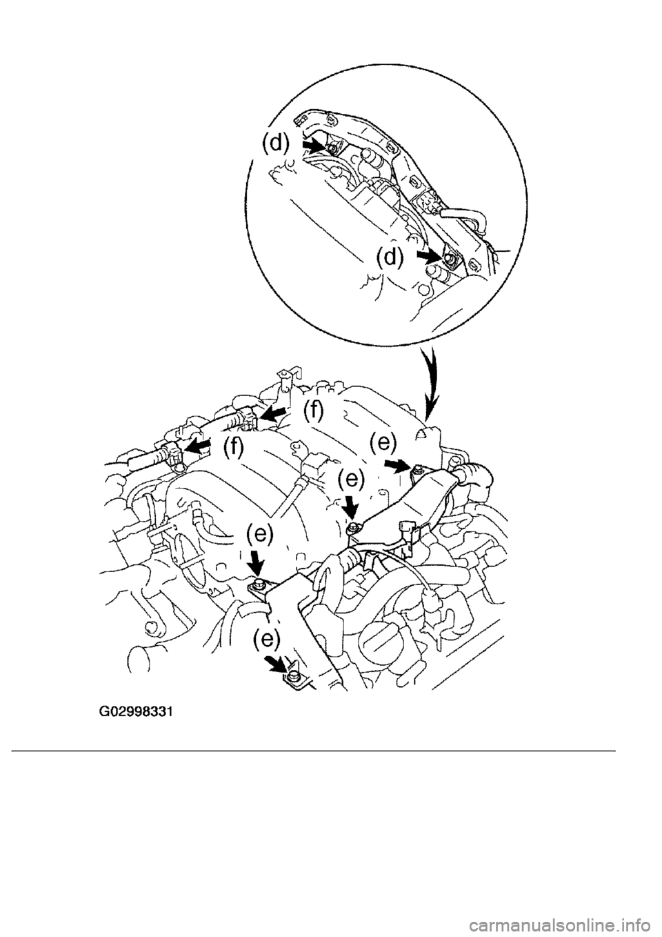
Fig. 64: Installing Intake Manifold Assy
Courtesy of TOYOTA MOTOR SALES, U.S.A., INC.
d. Install the engine wire protector (rear side) with the 2 bolts.
e. Install the engine wire protector (LH side) with the 4 bolts.
f. Install the 2 wire clamps on the en
gine wire (RH side) to the brackets on the RH delivery pipe.
Page 3345 of 4500
Page 3346 of 4500
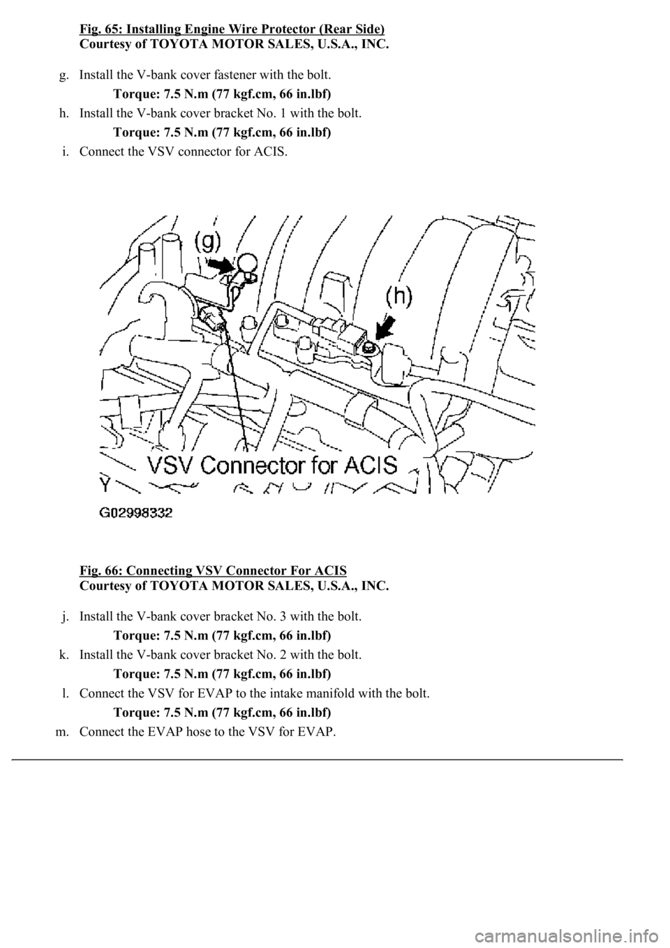
Fig. 65: Installing Engine Wire Protector (Rear Side)
Courtesy of TOYOTA MOTOR SALES, U.S.A., INC.
g. Install the V-bank cover fastener with the bolt.
Torque: 7.5 N.m (77 kgf.cm, 66 in.lbf)
h. Install the V-bank cover bracket No. 1 with the bolt.
Torque: 7.5 N.m (77 kgf.cm, 66 in.lbf)
i. Connect the VSV connector for ACIS.
Fig. 66: Connecting VSV Connector For ACIS
Courtesy of TOYOTA MOTOR SALES, U.S.A., INC.
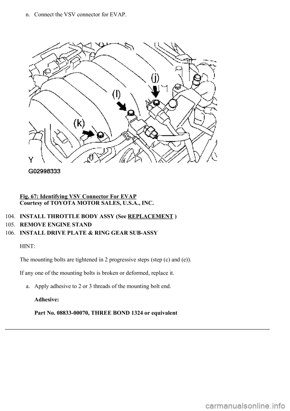
j. Install the V-bank cover bracket No. 3 with the bolt.
Torque: 7.5 N.m (77 kgf.cm, 66 in.lbf)
k. Install the V-bank cover bracket No. 2 with the bolt.
Torque: 7.5 N.m (77 kgf.cm, 66 in.lbf)
l. Connect the VSV for EVAP to the intake manifold with the bolt.
Torque: 7.5 N.m (77 kgf.cm, 66 in.lbf)
m. Connect the EVAP hose to the VSV for EVAP.
Page 3347 of 4500
n. Connect the VSV connector for EVAP.
Fig. 67: Identifying VSV Connector For EVAP
Courtesy of TOYOTA MOTOR SALES, U.S.A., INC.
104.INSTALL THROTTLE BODY ASSY (See REPLACEMENT
)
105.REMOVE ENGINE STAND
106.INSTALL DRIVE PLATE & RING GEAR SUB-ASSY
HINT:
The mounting bolts are tightened in 2 progressive steps (step (c) and (e)).
If any one of the mounting bolts is broken or deformed, replace it.
a. Apply adhesive to 2 or 3 threads of the mounting bolt end.
Adhesive:
Part No. 08833-00070, THREE BOND 1324 or equivalent
Page 3348 of 4500
Fig. 68: Applying Adhesive To Threads Of Mounting Bolt
Courtesy of TOYOTA MOTOR SALES, U.S.A., INC.
b. Install the front spacer, drive plate and rear spacer on the crankshaft.
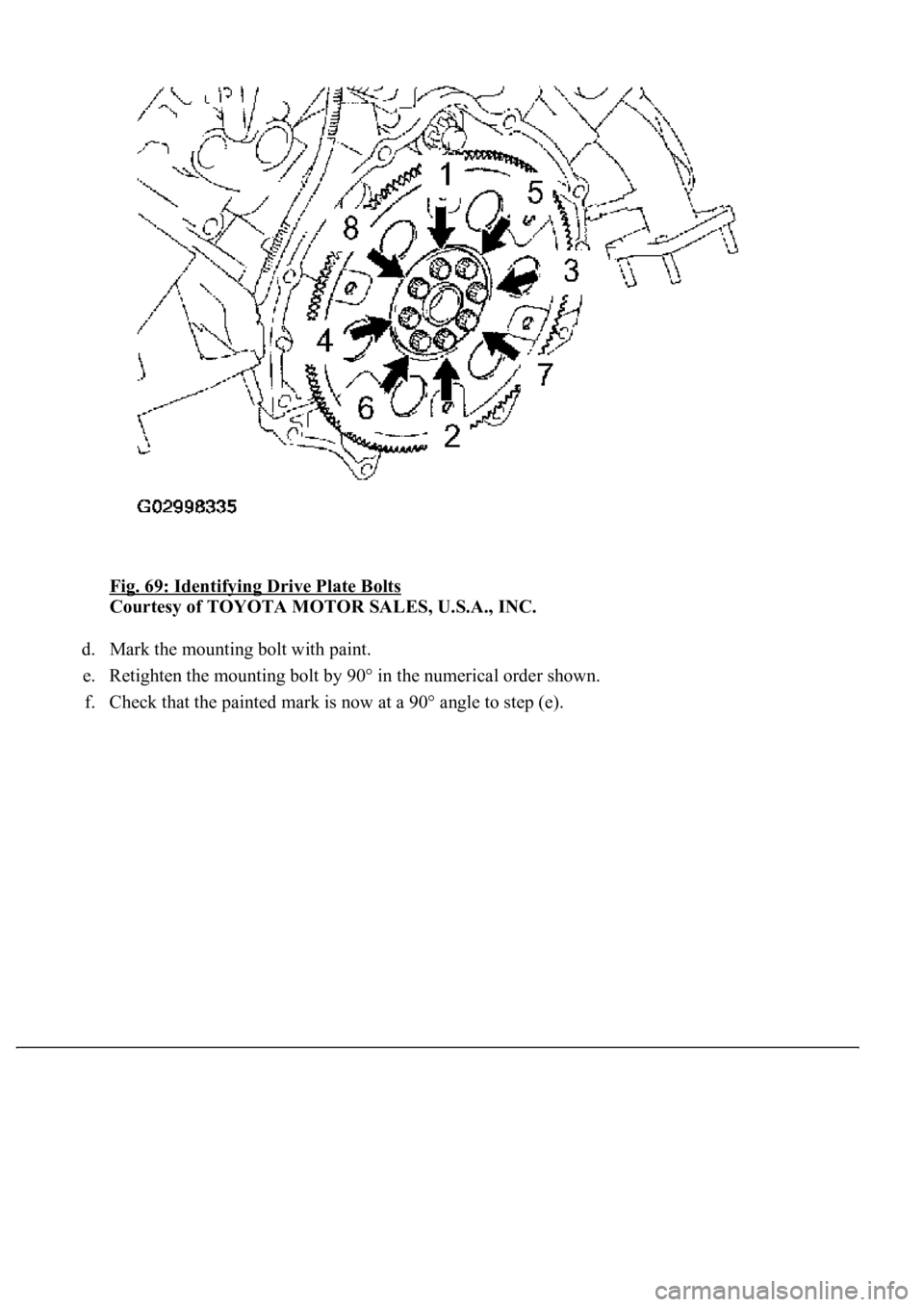
c. Install and uniformly tighten the 8 mounting bolts in several passes in the sequence shown in the
illustration.
Torque: 49 N.m (500 kgf.cm, 36 ft.lbf)
If any one of the mounting bolts does not meet the torque specification, replace the mounting bolt.
Page 3349 of 4500
Fig. 69: Identifying Drive Plate Bolts
Courtesy of TOYOTA MOTOR SALES, U.S.A., INC.
d. Mark the mounting bolt with paint.
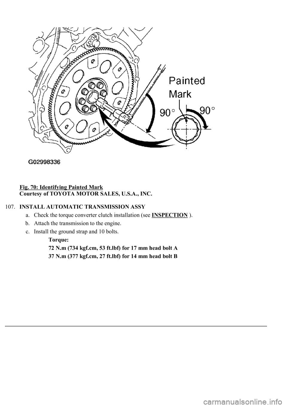
e. Retighten the mounting bolt by 90° in the numerical order shown.
f. Check that the painted mark is now at a 90° an
gle to step (e).
Page 3350 of 4500
Fig. 70: Identifying Painted Mark
Courtesy of TOYOTA MOTOR SALES, U.S.A., INC.
107.INSTALL AUTOMATIC TRANSMISSION ASSY
a. Check the torque converter clutch installation (see INSPECTION
).
b. Attach the transmission to the engine.
c. Install the ground strap and 10 bolts.
Torque:
72 N.m (734 kgf.cm, 53 ft.lbf) for 17 mm head bolt A
37 N.m (377 kgf.cm, 27 ft.lbf) for 14 mm head bolt B
Trending: remote start, C1752, fuel pump, power steering fluid, Navi, replacement, power steering
