LEXUS LS430 2003 Factory Repair Manual
Manufacturer: LEXUS, Model Year: 2003,
Model line: LS430,
Model: LEXUS LS430 2003
Pages: 4500, PDF Size: 87.45 MB
LEXUS LS430 2003 Factory Repair Manual
LS430 2003
LEXUS
LEXUS
https://www.carmanualsonline.info/img/36/57050/w960_57050-0.png
LEXUS LS430 2003 Factory Repair Manual
Trending: steering wheel, engine mechanical, wheel torque, B2799, Max cool damper sensor, pcv, CD changer
Page 3361 of 4500
140.INSTALL ENGINE UNDER COVER NO.2
141.INSTALL ENGINE UNDER COVER NO.1
142.INSTALL FRONT WHEEL
143.INSTALL AIR CLEANER ASSY
144.INSTALL INTAKE AIR CONNECTOR PIPE
145.INSTALL AIR CLEANER INLET NO.1
146.INSTALL V-BANK COVER
147.INSTALL HOOD SUB-ASSY (See ADJUSTMENT
and OVERHAUL )
148.CONNECT BATTERY NEGATIVE TERMINAL
149.ADD AUTOMATIC TRANSMISSION FLUID
150.ADD ENGINE COOLANT (See REPLACEMENT
)
151.ADD ENGINE OIL (See ON
-VEHICLE INSPECTION )
152.ADD POWER STEERING FLUID
153.BLEED POWER STEERING FLUID
154.INSPECT AUTOMATIC TRANSMISSION FLUID (See ADJUSTMENT
)
155.INSPECT ENGINE OIL LEAKS
156.CHECK FOR ENGINE COOLANT LEAKS
157.INSPECT FOR FUEL LEAKS
158.CHECK FOR EXHAUST GAS LEAKS
159.INSPECT AND ADJUST FRONT WHEEL ALIGNMENT
160.INSPECT IGNITION TIMING
161.INSPECT ENGINE IDLE SPEED
162.INSPECT CO/HC
163.ADJUST ENGINE (See INSPECTION
)
164.CHECK ABS SPEED SENSOR SIGNAL (See TEST MODE PROCEDURE
)
OVERHAUL
1.REMOVE SPARK PLUG
2.REMOVE OIL FILLER CAP SUB-ASSY
3.REMOVE CYLINDER HEAD COVER SUB-ASSY LH
a. Remove the 9 bolts, 9 seal washers, cylinder head cover and gasket.
4.REMOVE CYLINDER HEAD COVER SUB-ASSY
a. Remove the 9 bolts, 9 seal washers, c
ylinder head cover and gasket.
Page 3362 of 4500
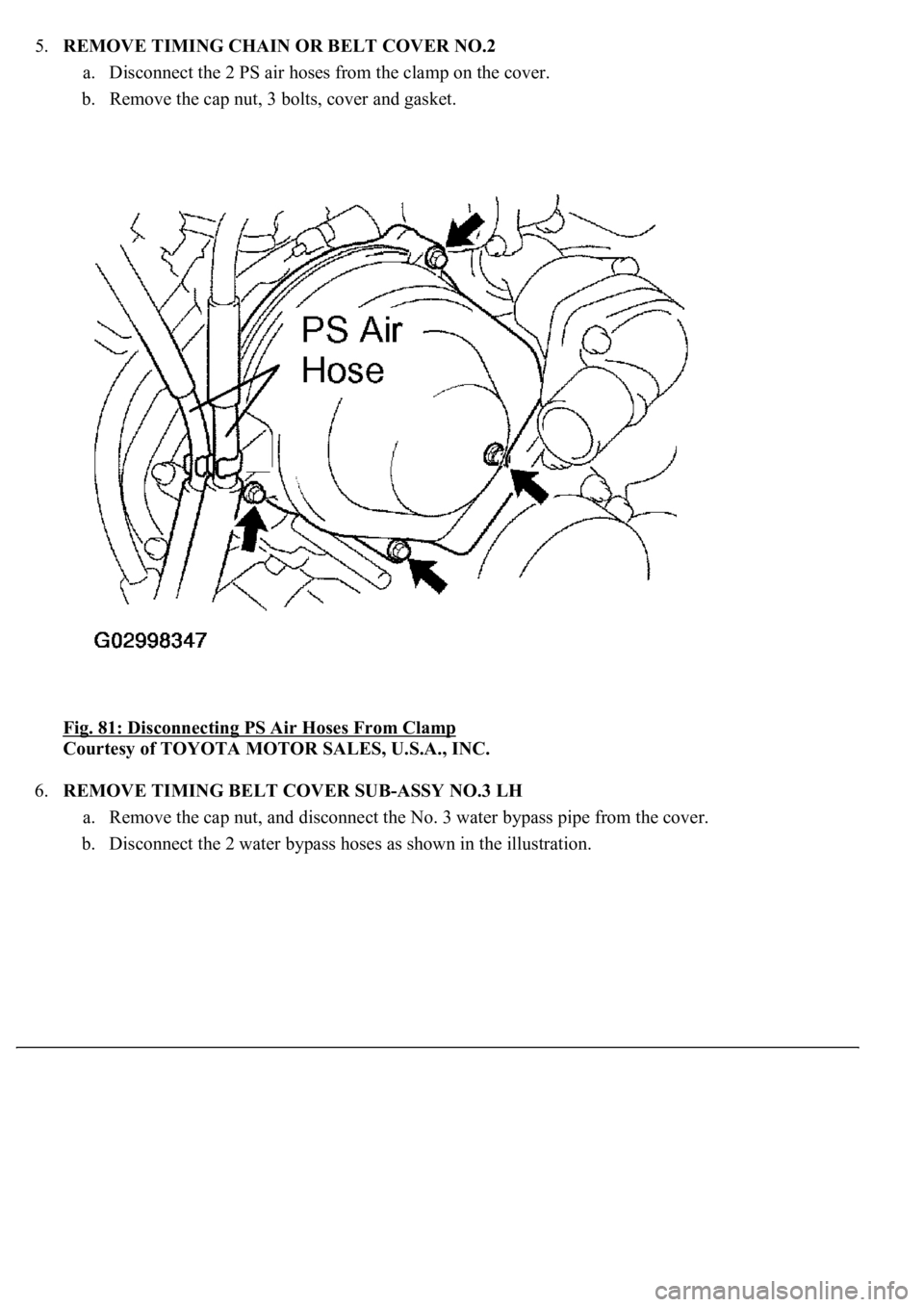
5.REMOVE TIMING CHAIN OR BELT COVER NO.2
a. Disconnect the 2 PS air hoses from the clamp on the cover.
b. Remove the cap nut, 3 bolts, cover and gasket.
Fig. 81: Disconnecting PS Air Hoses From Clamp
Courtesy of TOYOTA MOTOR SALES, U.S.A., INC.
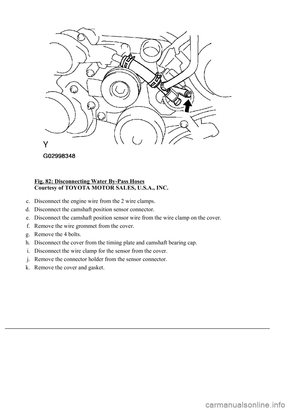
6.REMOVE TIMING BELT COVER SUB-ASSY NO.3 LH
a. Remove the cap nut, and disconnect the No. 3 water bypass pipe from the cover.
b. Disconnect the 2 water bypass hoses as shown in the illustration.
Page 3363 of 4500
Fig. 82: Disconnecting Water By-Pass Hoses
Courtesy of TOYOTA MOTOR SALES, U.S.A., INC.
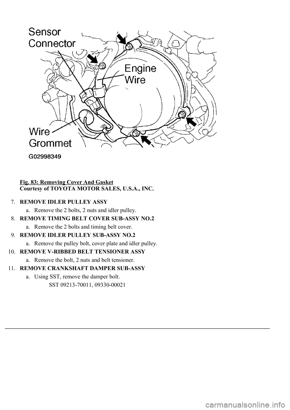
c. Disconnect the engine wire from the 2 wire clamps.
d. Disconnect the camshaft position sensor connector.
e. Disconnect the camshaft position sensor wire from the wire clamp on the cover.
f. Remove the wire grommet from the cover.
g. Remove the 4 bolts.
h. Disconnect the cover from the timing plate and camshaft bearing cap.
i. Disconnect the wire clamp for the sensor from the cover.
j. Remove the connector holder from the sensor connector.
k. Remove the cover and
gasket.
Page 3364 of 4500
Fig. 83: Removing Cover And Gasket
Courtesy of TOYOTA MOTOR SALES, U.S.A., INC.
7.REMOVE IDLER PULLEY ASSY
a. Remove the 2 bolts, 2 nuts and idler pulley.
8.REMOVE TIMING BELT COVER SUB-ASSY NO.2
a. Remove the 2 bolts and timing belt cover.
9.REMOVE IDLER PULLEY SUB-ASSY NO.2
a. Remove the pulley bolt, cover plate and idler pulley.
10.REMOVE V-RIBBED BELT TENSIONER ASSY
a. Remove the bolt, 2 nuts and belt tensioner.
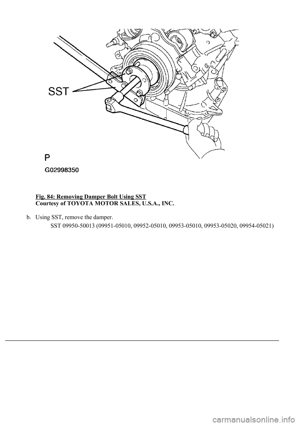
11.REMOVE CRANKSHAFT DAMPER SUB-ASSY
a. Using SST, remove the damper bolt.
SST 09213-70011, 09330-00021
Page 3365 of 4500
Fig. 84: Removing Damper Bolt Using SST
Courtesy of TOYOTA MOTOR SALES, U.S.A., INC.
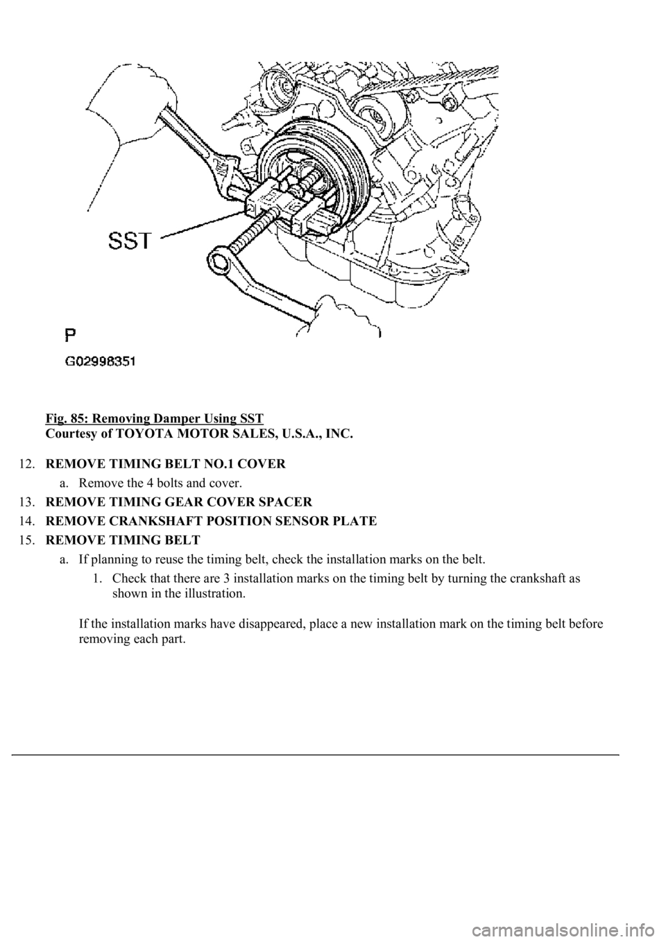
b. Using SST, remove the damper.
<00360036003700030013001c001c001800130010001800130013001400160003000b0013001c001c00180014001000130018001300140013000f00030013001c001c00180015001000130018001300140013000f00030013001c001c001800160010001300
18001300140013000f00030013001c001c0018001600100013[5020, 09954-05021)
Page 3366 of 4500
Fig. 85: Removing Damper Using SST
Courtesy of TOYOTA MOTOR SALES, U.S.A., INC.
12.REMOVE TIMING BELT NO.1 COVER
a. Remove the 4 bolts and cover.
13.REMOVE TIMING GEAR COVER SPACER
14.REMOVE CRANKSHAFT POSITION SENSOR PLATE
15.REMOVE TIMING BELT
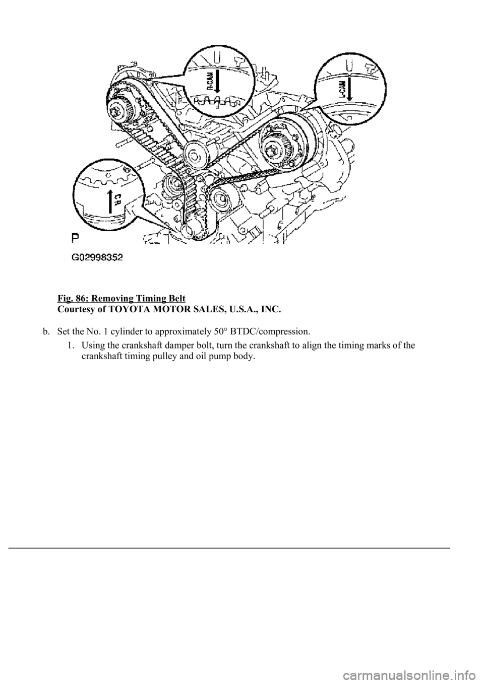
a. If planning to reuse the timing belt, check the installation marks on the belt.
1. Check that there are 3 installation marks on the timing belt by turning the crankshaft as
shown in the illustration.
If the installation marks have disappeared, place a new installation mark on the timing belt before
removing each part.
Page 3367 of 4500
Fig. 86: Removing Timing Belt
Courtesy of TOYOTA MOTOR SALES, U.S.A., INC.
b. Set the No. 1 cylinder to approximately 50° BTDC/compression.
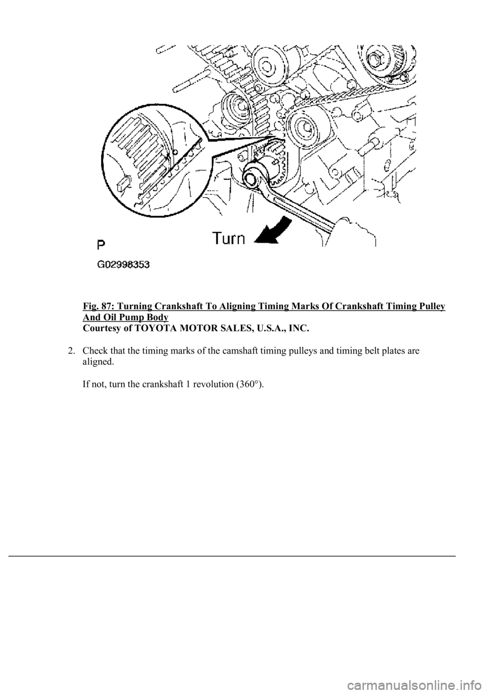
1. Using the crankshaft damper bolt, turn the crankshaft to align the timing marks of the
crankshaft timing pulley and oil pump body.
Page 3368 of 4500
Fig. 87: Turning Crankshaft To Aligning Timing Marks Of Crankshaft Timing Pulley
And Oil Pump Body
Courtesy of TOYOTA MOTOR SALES, U.S.A., INC.
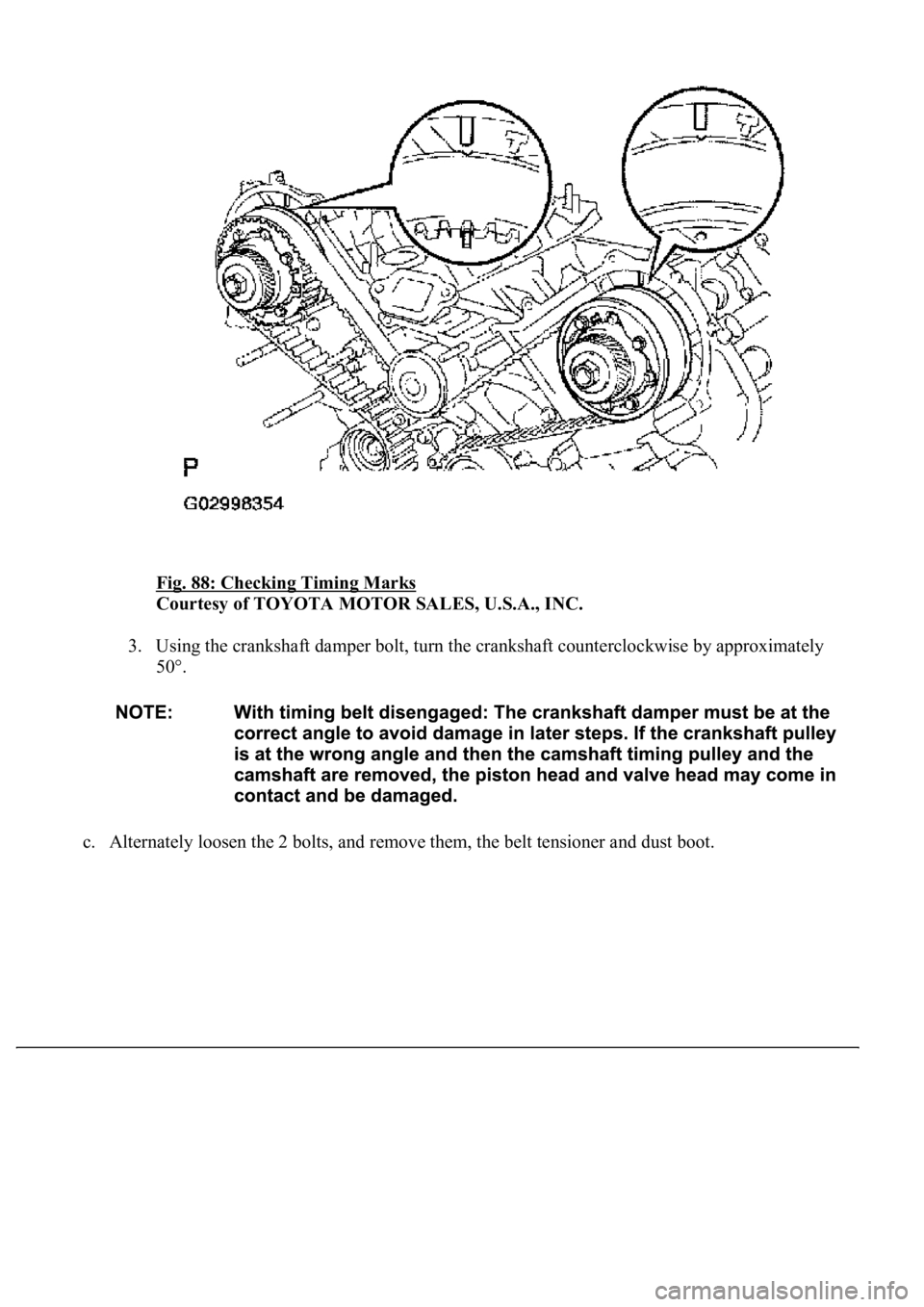
2. Check that the timing marks of the camshaft timing pulleys and timing belt plates are
aligned.
If not, turn the crankshaft 1 revolution (360°).
Page 3369 of 4500
Fig. 88: Checking Timing Marks
Courtesy of TOYOTA MOTOR SALES, U.S.A., INC.
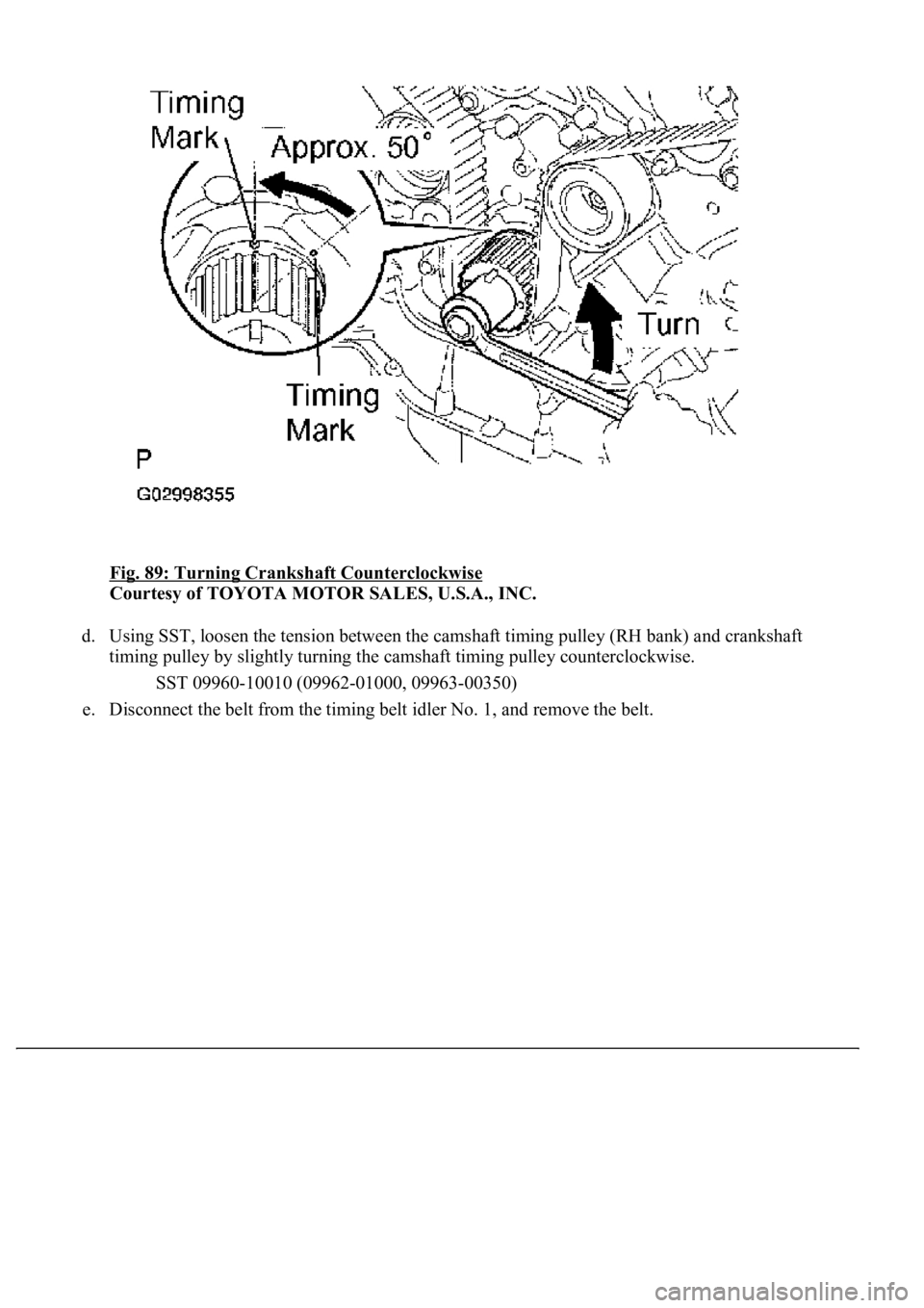
3. Using the crankshaft damper bolt, turn the crankshaft counterclockwise by approximately
50°.
c. Alternatel
y loosen the 2 bolts, and remove them, the belt tensioner and dust boot.
Page 3370 of 4500
Fig. 89: Turning Crankshaft Counterclockwise
Courtesy of TOYOTA MOTOR SALES, U.S.A., INC.
d. Using SST, loosen the tension between the camshaft timing pulley (RH bank) and crankshaft
timing pulley by slightly turning the camshaft timing pulley counterclockwise.
SST 09960-10010 (09962-01000, 09963-00350)
e. Disconnect the belt from the timing belt idler No. 1, and remove the belt.
Trending: mileage, head, instrument cluster, boot, odometer, evaporator, Spd

