LEXUS LS430 2003 Factory Repair Manual
Manufacturer: LEXUS, Model Year: 2003,
Model line: LS430,
Model: LEXUS LS430 2003
Pages: 4500, PDF Size: 87.45 MB
LEXUS LS430 2003 Factory Repair Manual
LS430 2003
LEXUS
LEXUS
https://www.carmanualsonline.info/img/36/57050/w960_57050-0.png
LEXUS LS430 2003 Factory Repair Manual
Trending: zero point calibration, warning light, glove box, washer fluid, low beam, B2776, adding oil
Page 3651 of 4500
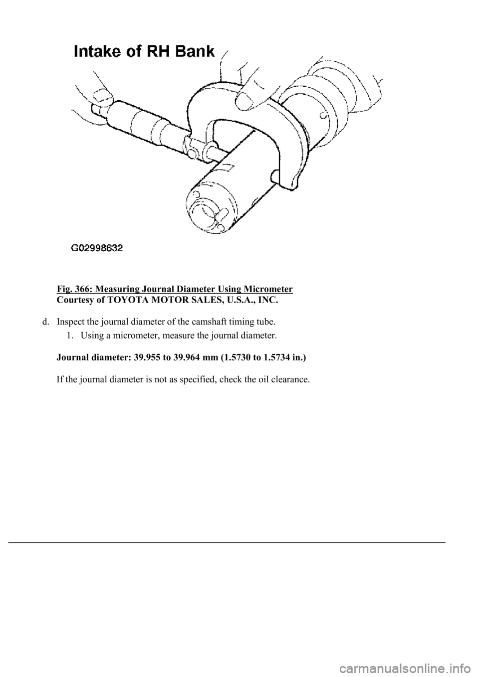
Fig. 366: Measuring Journal Diameter Using Micrometer
Courtesy of TOYOTA MOTOR SALES, U.S.A., INC.
d. Inspect the journal diameter of the camshaft timing tube.
1. Using a micrometer, measure the journal diameter.
<002d00520058005500510044004f00030047004c004400500048005700480055001d00030016001c0011001c0018001800030057005200030016001c0011001c001900170003005000500003000b001400110018001a001600130003005700520003001400
110018001a001600170003004c00510011000c[
If the
journal diameter is not as specified, check the oil clearance.
Page 3652 of 4500
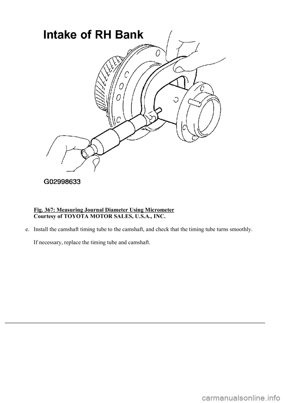
Fig. 367: Measuring Journal Diameter Using Micrometer
Courtesy of TOYOTA MOTOR SALES, U.S.A., INC.
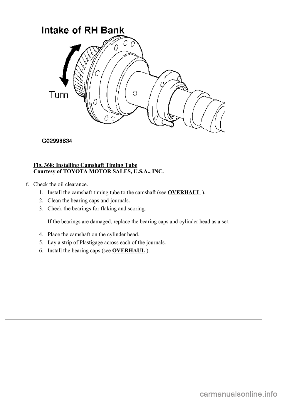
e. Install the camshaft timing tube to the camshaft, and check that the timing tube turns smoothly.
If necessar
y, replace the timing tube and camshaft.
Page 3653 of 4500
Fig. 368: Installing Camshaft Timing Tube
Courtesy of TOYOTA MOTOR SALES, U.S.A., INC.
f. Check the oil clearance.
1. Install the camshaft timing tube to the camshaft (see OVERHAUL
).
2. Clean the bearing caps and journals.
3. Check the bearings for flaking and scoring.
If the bearings are damaged, replace the bearing caps and cylinder head as a set.
4. Place the camshaft on the cylinder head.
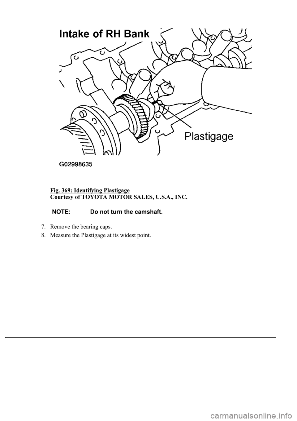
5. Lay a strip of Plastigage across each of the journals.
6. Install the bearing caps (see OVERHAUL
).
Page 3654 of 4500
Fig. 369: Identifying Plastigage
Courtesy of TOYOTA MOTOR SALES, U.S.A., INC.
7. Remove the bearing caps.
8. Measure the Plastigage at its widest point.
Page 3655 of 4500
Fig. 370: Measuring Plastigage At Widest Point
Courtesy of TOYOTA MOTOR SALES, U.S.A., INC.
STANDARD OIL CLEARANCE:
OIL CLEARANCE SPECIFICATIONS
MAXIMUM OIL CLEARANCE:
MAXIMUM OIL CLEARANCE SPECIFICATIONS
If the oil clearance is greater than the maximum, replace the camshaft and timing tube. If
necessary, replace the bearing caps and cylinder head as a set.
9. Completely remove the Plastigage.
10. Remove the camshaft.
Camshaft journal0.030 to 0.067 mm (0.0012 to 0.0026 in.)
Camshaft timing tube journal0.036 to 0.057 mm (0.0014 to 0.0022 in.)
Camshaft journal0.100 mm (0.0039 in.)
Camshaft timing tube journal0.085 mm (0.0033 in.)
Page 3656 of 4500
11. Remove the camshaft timing tube from the camshaft.
Fig. 371: Measuring Thrust Clearance Using Dial Indicator
Courtesy of TOYOTA MOTOR SALES, U.S.A., INC.
g. Check the thrust clearance.
1. Install the camshaft timing tube to the camshaft (see OVERHAUL
).
2. Install the camshaft (see OVERHAUL
).
3. Using a dial indicator, measure the thrust clearance while moving the camshaft back and
forth.
Standard thrust clearance: 0.060 to 0.100 mm (0.0024 to 0.0039 in.) Maximum thrust
clearance: 0.13 mm (0.0051 in.)
If the thrust clearance is greater than the maximum, replace the camshaft. If necessary,
replace the bearing caps and cylinder head as a set.
4. Remove the camshaft.
5. Remove the camshaft timing tube from the camshaft.
h. Check the gear backlash.
1. Install the drive
gear to the camshaft timing tube (see OVERHAUL ).
Page 3657 of 4500
2. Install the camshaft timing tube to the camshaft (see OVERHAUL ).
3. Install the camshaft and No. 2 camshaft without installing the camshaft sub-gear and front
bearing cap (see OVERHAUL
).
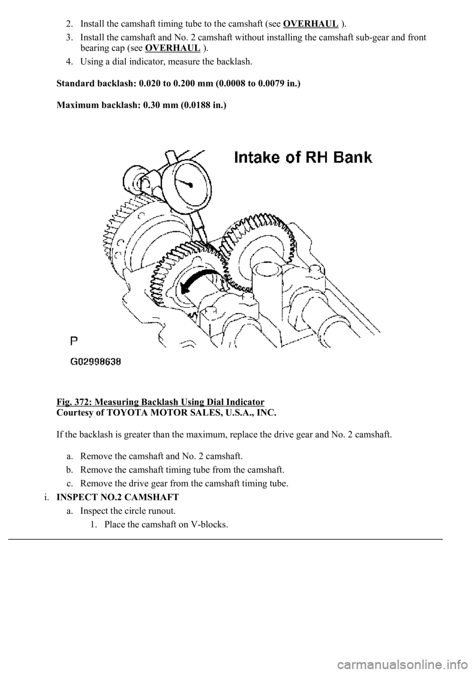
4. Using a dial indicator, measure the backlash.
Standard backlash: 0.020 to 0.200 mm (0.0008 to 0.0079 in.)
Maximum backlash: 0.30 mm (0.0188 in.)
Fig. 372: Measuring Backlash Using Dial Indicator
Courtesy of TOYOTA MOTOR SALES, U.S.A., INC.
If the backlash is greater than the maximum, replace the drive gear and No. 2 camshaft.
a. Remove the camshaft and No. 2 camshaft.
b. Remove the camshaft timing tube from the camshaft.
c. Remove the drive gear from the camshaft timing tube.
i.INSPECT NO.2 CAMSHAFT
a. Inspect the circle runout.
1. Place the camshaft on V-
blocks.
Page 3658 of 4500
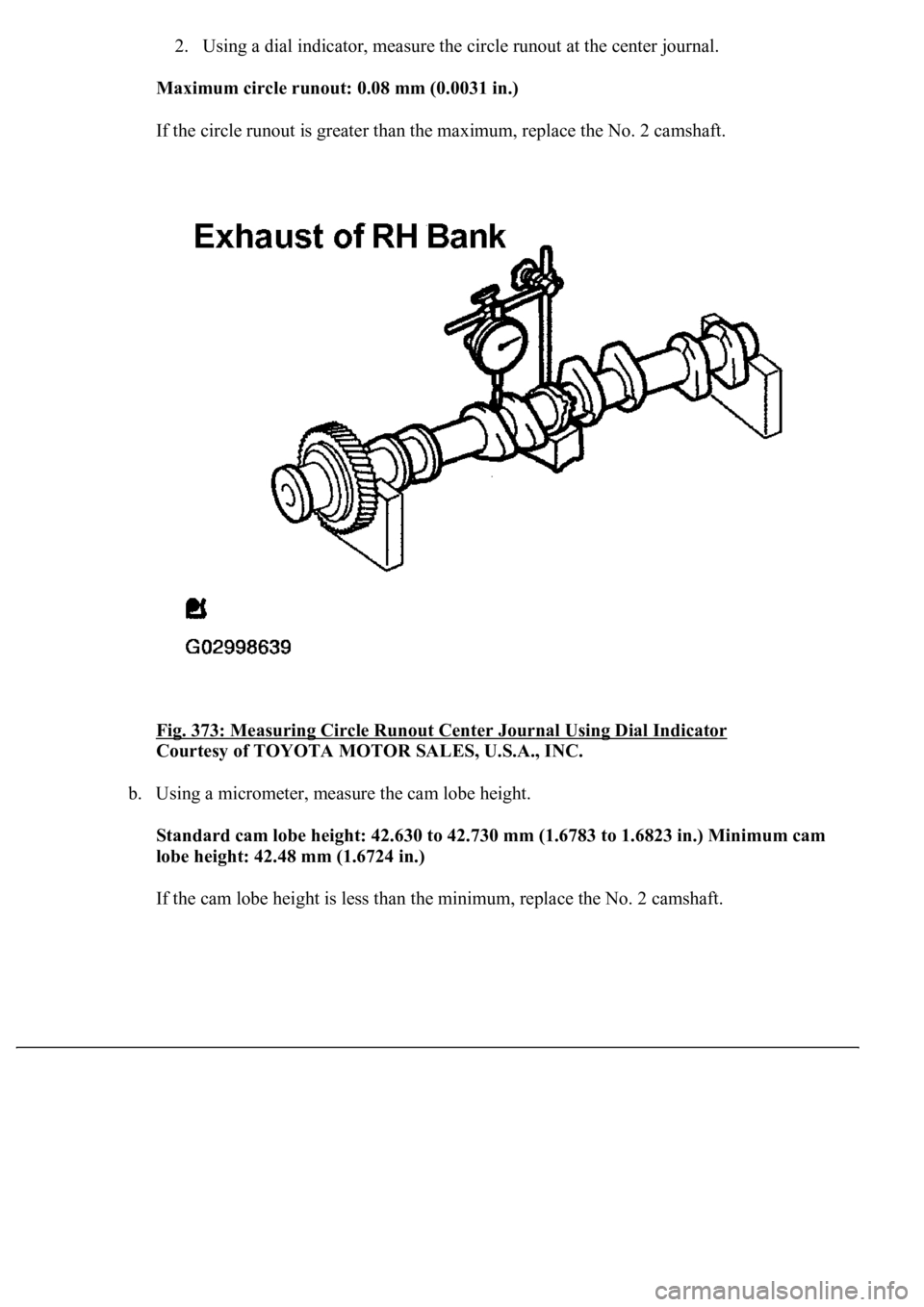
2. Using a dial indicator, measure the circle runout at the center journal.
Maximum circle runout: 0.08 mm (0.0031 in.)
If the circle runout is greater than the maximum, replace the No. 2 camshaft.
Fig. 373: Measuring Circle Runout Center Journal Using Dial Indicator
Courtesy of TOYOTA MOTOR SALES, U.S.A., INC.
b. Using a micrometer, measure the cam lobe height.
<0036005700440051004700440055004700030046004400500003004f0052004500480003004b0048004c004a004b0057001d00030017001500110019001600130003005700520003001700150011001a001600130003005000500003000b00140011001900
1a001b00160003005700520003001400110019001b00150016[ in.) Minimum cam
lobe height: 42.48 mm (1.6724 in.)
If the cam lobe height is less than the minimum, replace the No. 2 camshaft.
Page 3659 of 4500
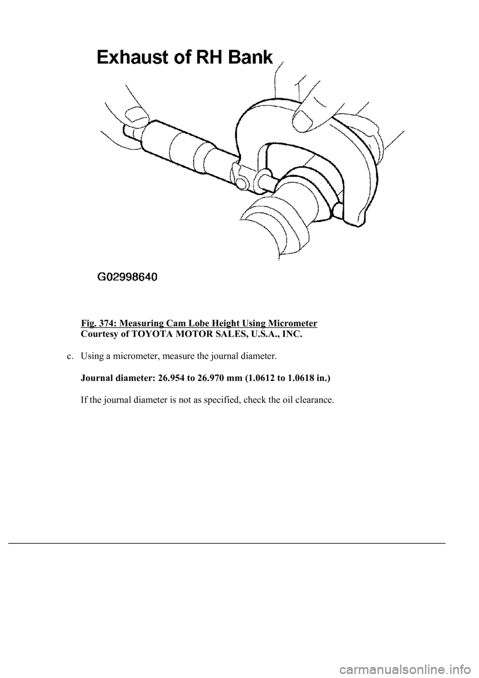
Fig. 374: Measuring Cam Lobe Height Using Micrometer
Courtesy of TOYOTA MOTOR SALES, U.S.A., INC.
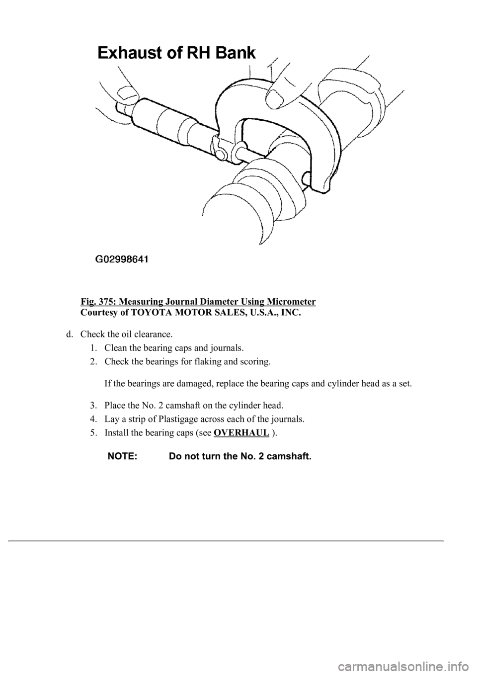
c. Using a micrometer, measure the journal diameter.
Journal diameter: 26.954 to 26.970 mm (1.0612 to 1.0618 in.)
If the journal diameter is not as specified, check the oil clearance.
Page 3660 of 4500
Fig. 375: Measuring Journal Diameter Using Micrometer
Courtesy of TOYOTA MOTOR SALES, U.S.A., INC.
d. Check the oil clearance.
1. Clean the bearing caps and journals.
2. Check the bearings for flaking and scoring.
If the bearings are damaged, replace the bearing caps and cylinder head as a set.
3. Place the No. 2 camshaft on the cylinder head.
4. Lay a strip of Plastigage across each of the journals.
5. Install the bearing caps (see OVERHAUL
).
Trending: wiring, exhaust manifold, catalytic converter, wheel alignment, tow bar, set clock, fuel filter
