LEXUS LS430 2003 Factory Repair Manual
Manufacturer: LEXUS, Model Year: 2003,
Model line: LS430,
Model: LEXUS LS430 2003
Pages: 4500, PDF Size: 87.45 MB
LEXUS LS430 2003 Factory Repair Manual
LS430 2003
LEXUS
LEXUS
https://www.carmanualsonline.info/img/36/57050/w960_57050-0.png
LEXUS LS430 2003 Factory Repair Manual
Trending: CD changer, wheel size, warning lights, Sp1, catalytic converter, service interval, window
Page 3691 of 4500
Fig. 407: Exploded View Of Cylinder Block Assy Components
Courtesy of TOYOTA MOTOR SALES, U.S.A., INC.
OVERHAUL
HINT:
Page 3692 of 4500
Thoroughly clean all parts to be assembled.
Before installing the parts, apply new engine oil to all sliding and rotating surfaces.
Replace all gaskets, O-rings and oil seals with new parts.
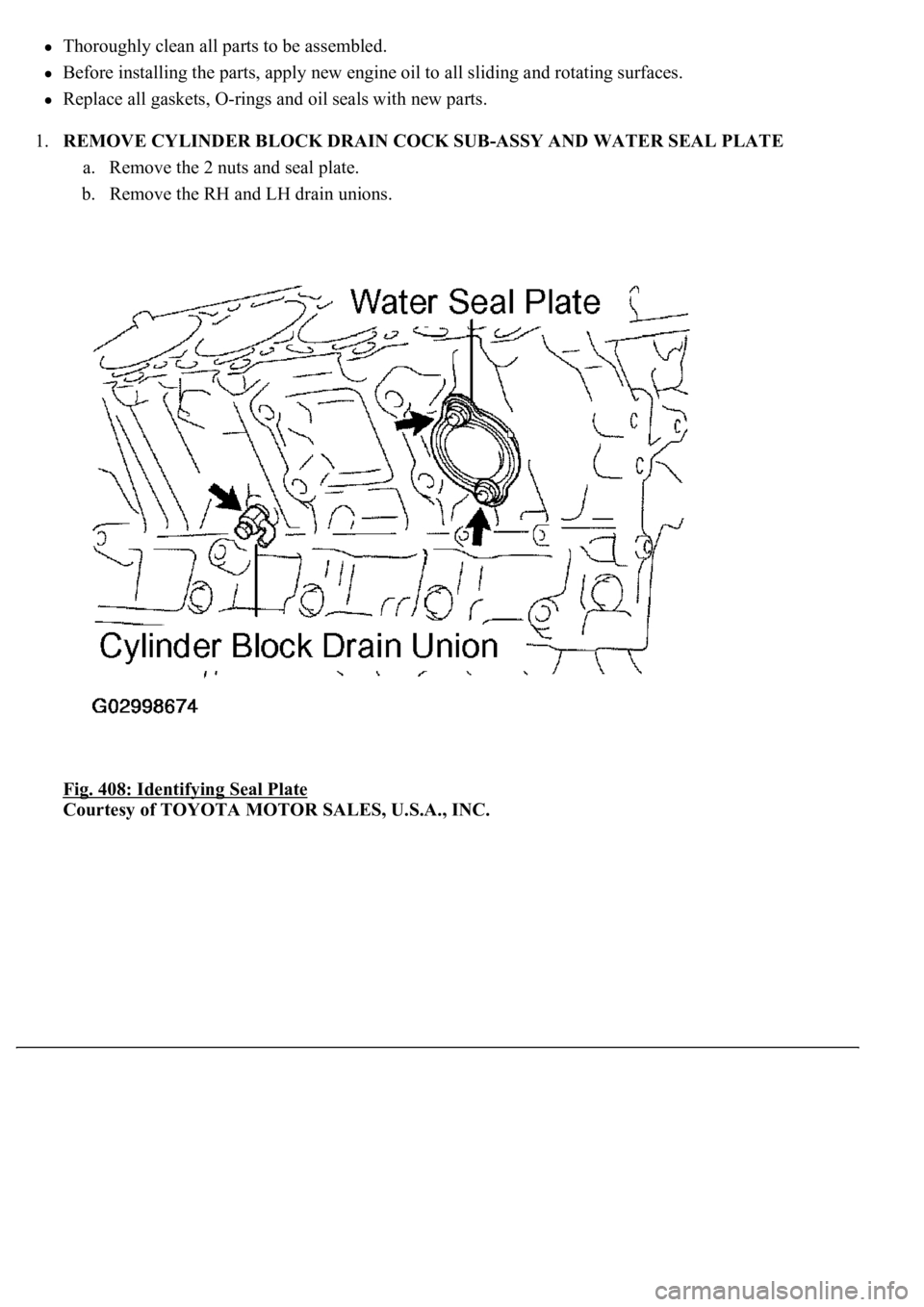
1.REMOVE CYLINDER BLOCK DRAIN COCK SUB-ASSY AND WATER SEAL PLATE
a. Remove the 2 nuts and seal plate.
b. Remove the RH and LH drain unions.
Fig. 408: Identifying Seal Plate
Courtesy of TOYOTA MOTOR SALES, U.S.A., INC.
Page 3693 of 4500
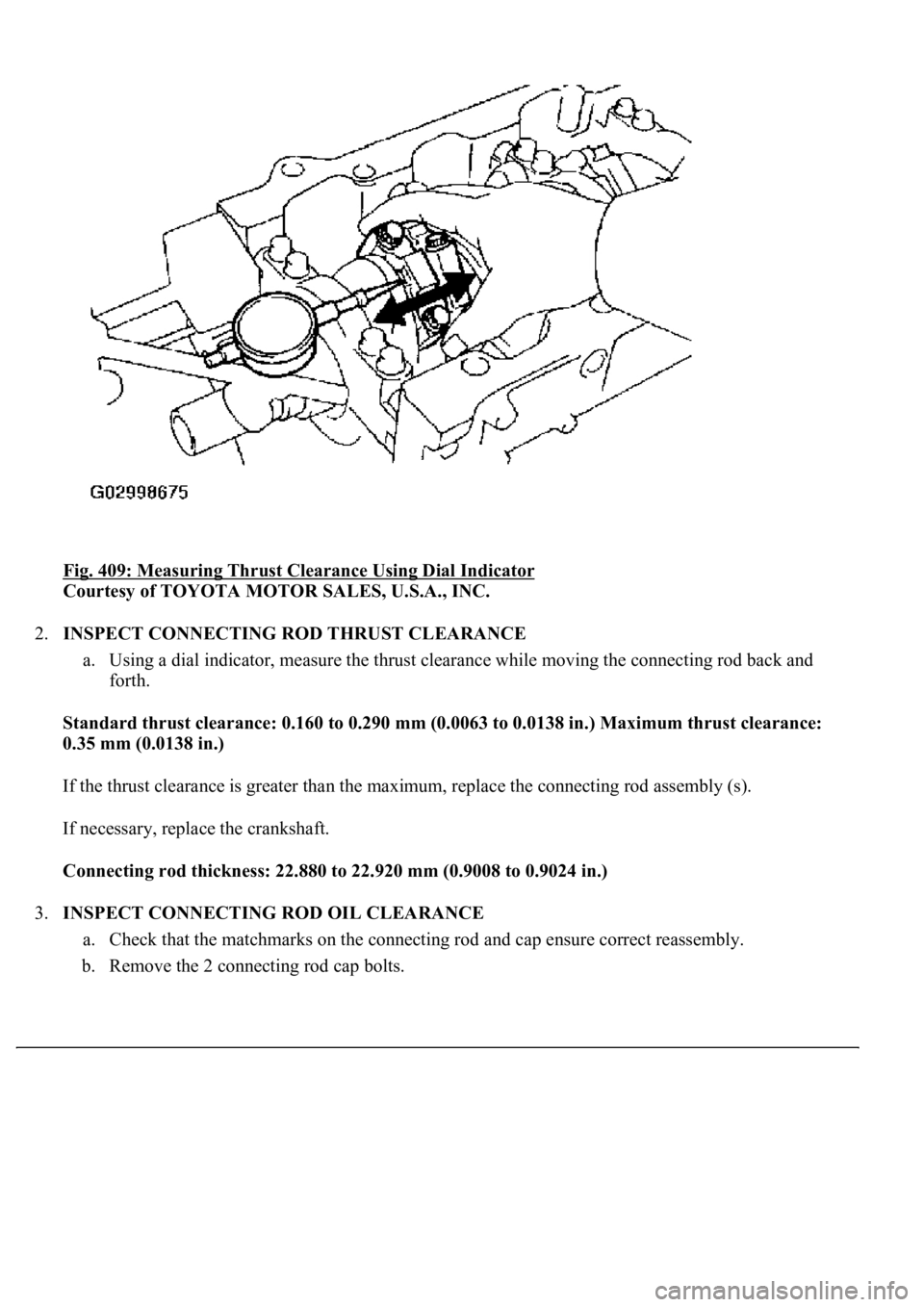
Fig. 409: Measuring Thrust Clearance Using Dial Indicator
Courtesy of TOYOTA MOTOR SALES, U.S.A., INC.
2.INSPECT CONNECTING ROD THRUST CLEARANCE
a. Using a dial indicator, measure the thrust clearance while moving the connecting rod back and
forth.
<0036005700440051004700440055004700030057004b005500580056005700030046004f0048004400550044005100460048001d0003001300110014001900130003005700520003001300110015001c00130003005000500003000b001300110013001300
190016000300570052000300130011001300140016001b0003[in.) Maximum thrust clearance:
0.35 mm (0.0138 in.)
If the thrust clearance is greater than the maximum, replace the connecting rod assembly (s).
If necessary, replace the crankshaft.
Connecting rod thickness: 22.880 to 22.920 mm (0.9008 to 0.9024 in.)
3.INSPECT CONNECTING ROD OIL CLEARANCE
a. Check that the matchmarks on the connecting rod and cap ensure correct reassembly.
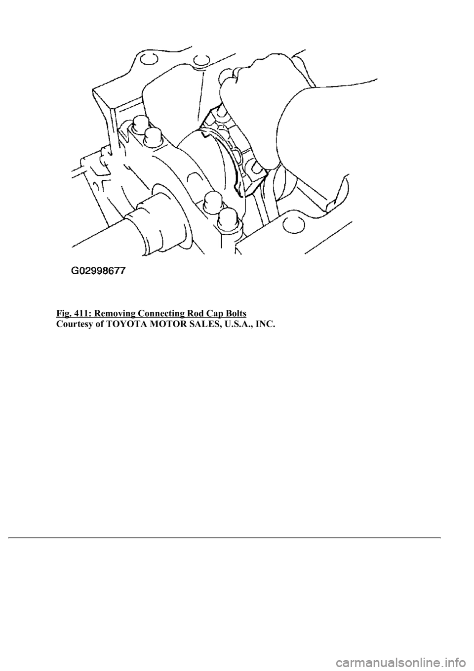
b. Remove the 2 connecting rod cap bolts.
Page 3694 of 4500
Fig. 410: Removing Connecting Rod Cap Bolts
Courtesy of TOYOTA MOTOR SALES, U.S.A., INC.
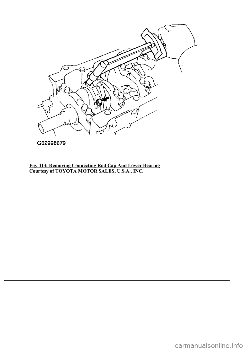
c. Using the removed connecting rod cap bolts, remove the connecting rod cap and lower bearing by
wiggling the connecting rod cap right and left.
HINT:Keep the lower bearing inserted with the connecting rod cap.
d. Clean the crank pin and bearing.
e. Check the crank pin and bearing for pitting and scratches.
If the crank pin or bearing is damaged, replace the bearings. If necessary, replace the crankshaft.
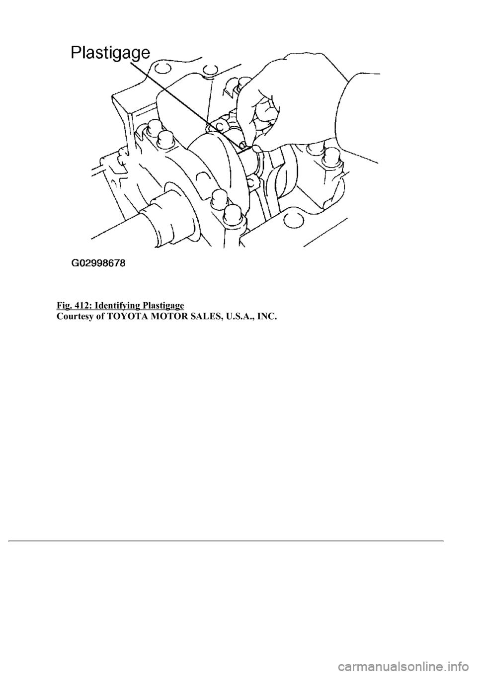
f. Lay a strip of Plastigage across the crank pin.
g. Install the connecting rod cap with the 2 bolts (see step 26).
h. Remove the 2 bolts, connectin
g rod cap and lower bearing (see steps (b) and (c) above).
Page 3695 of 4500
Fig. 411: Removing Connecting Rod Cap Bolts
Courtesy of TOYOTA MOTOR SALES, U.S.A., INC.
Page 3696 of 4500
Fig. 412: Identifying Plastigage
Courtesy of TOYOTA MOTOR SALES, U.S.A., INC.
Page 3697 of 4500
Fig. 413: Removing Connecting Rod Cap And Lower Bearing
Courtesy of TOYOTA MOTOR SALES, U.S.A., INC.
Page 3698 of 4500
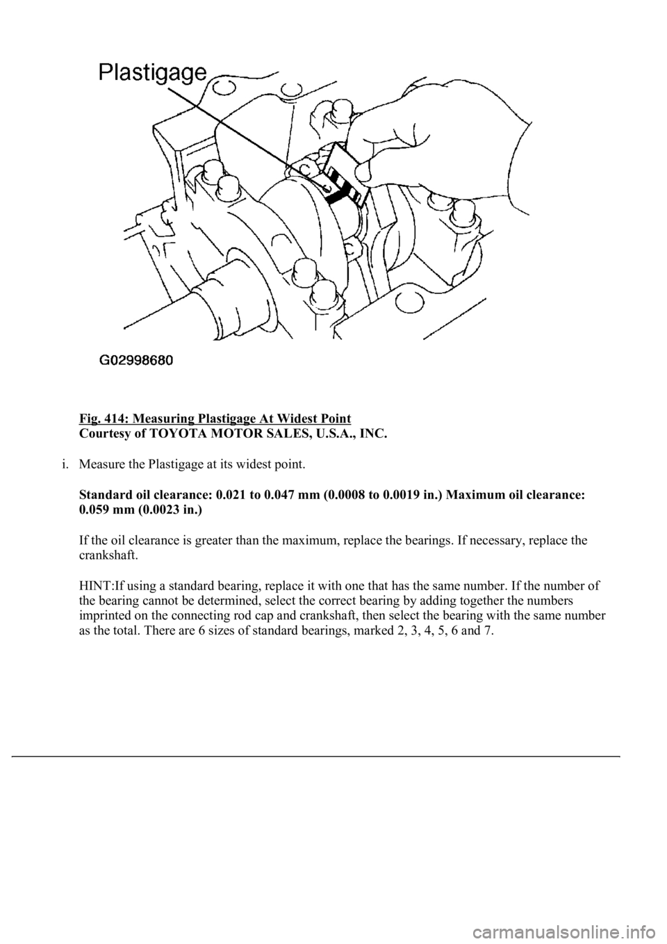
Fig. 414: Measuring Plastigage At Widest Point
Courtesy of TOYOTA MOTOR SALES, U.S.A., INC.
i. Measure the Plastigage at its widest point.
Standard oil clearance: 0.021 to 0.047 mm (0.0008 to 0.0019 in.) Maximum oil clearance:
0.059 mm (0.0023 in.)
If the oil clearance is greater than the maximum, replace the bearings. If necessary, replace the
crankshaft.
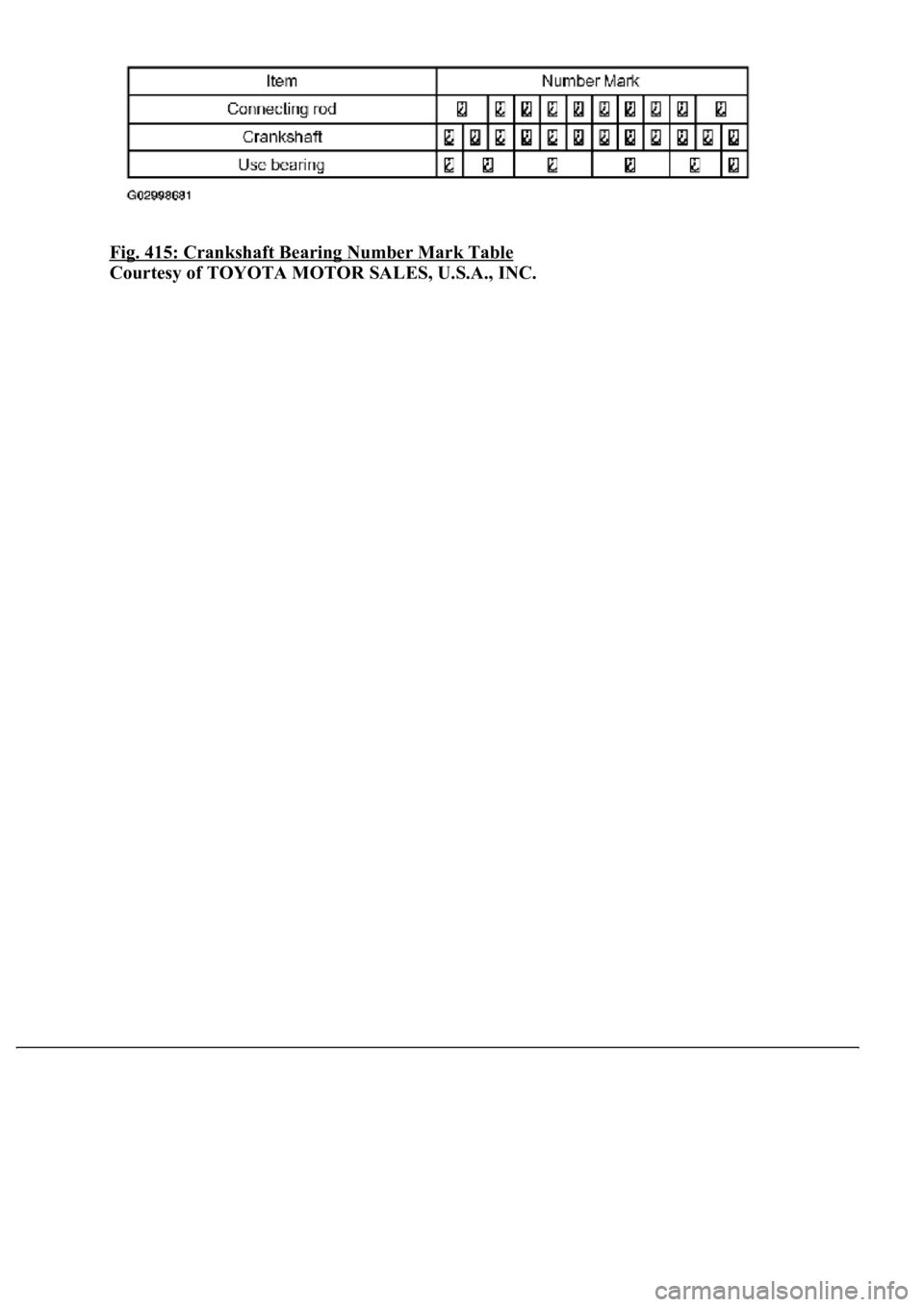
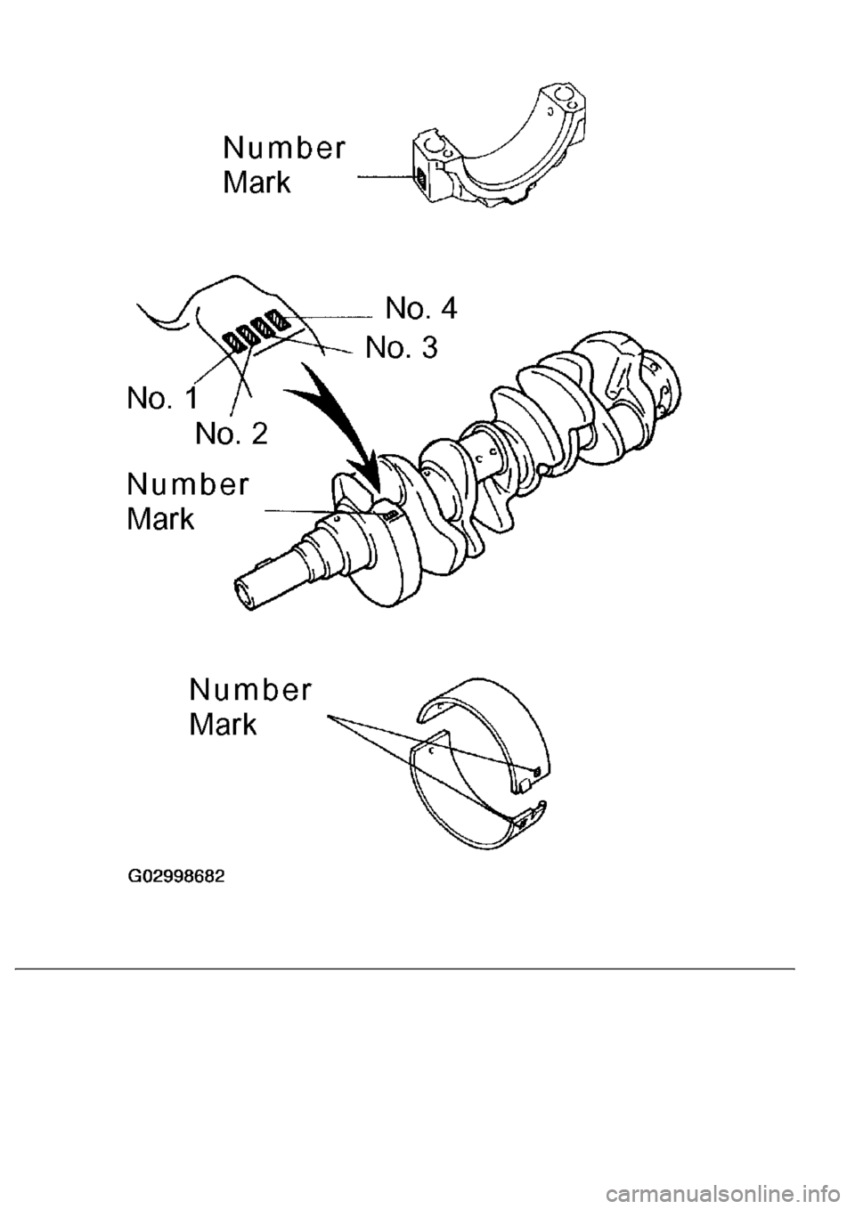
HINT:If using a standard bearing, replace it with one that has the same number. If the number of
the bearing cannot be determined, select the correct bearing by adding together the numbers
imprinted on the connecting rod cap and crankshaft, then select the bearing with the same number
as the total. There are 6 sizes of standard bearin
gs, marked 2, 3, 4, 5, 6 and 7.
Page 3699 of 4500
Fig. 415: Crankshaft Bearing Number Mark Table
Courtesy of TOYOTA MOTOR SALES, U.S.A., INC.
Page 3700 of 4500
Trending: AC Expansion Valve, display, seats, alternator, rear view mirror, spare tire, Suspension control
