LEXUS LS430 2003 Factory Repair Manual
Manufacturer: LEXUS, Model Year: 2003,
Model line: LS430,
Model: LEXUS LS430 2003
Pages: 4500, PDF Size: 87.45 MB
LEXUS LS430 2003 Factory Repair Manual
LS430 2003
LEXUS
LEXUS
https://www.carmanualsonline.info/img/36/57050/w960_57050-0.png
LEXUS LS430 2003 Factory Repair Manual
Trending: brakes, Door lock actuator, instrument cluster, navigation system, fuse, service indicator, reset
Page 821 of 4500
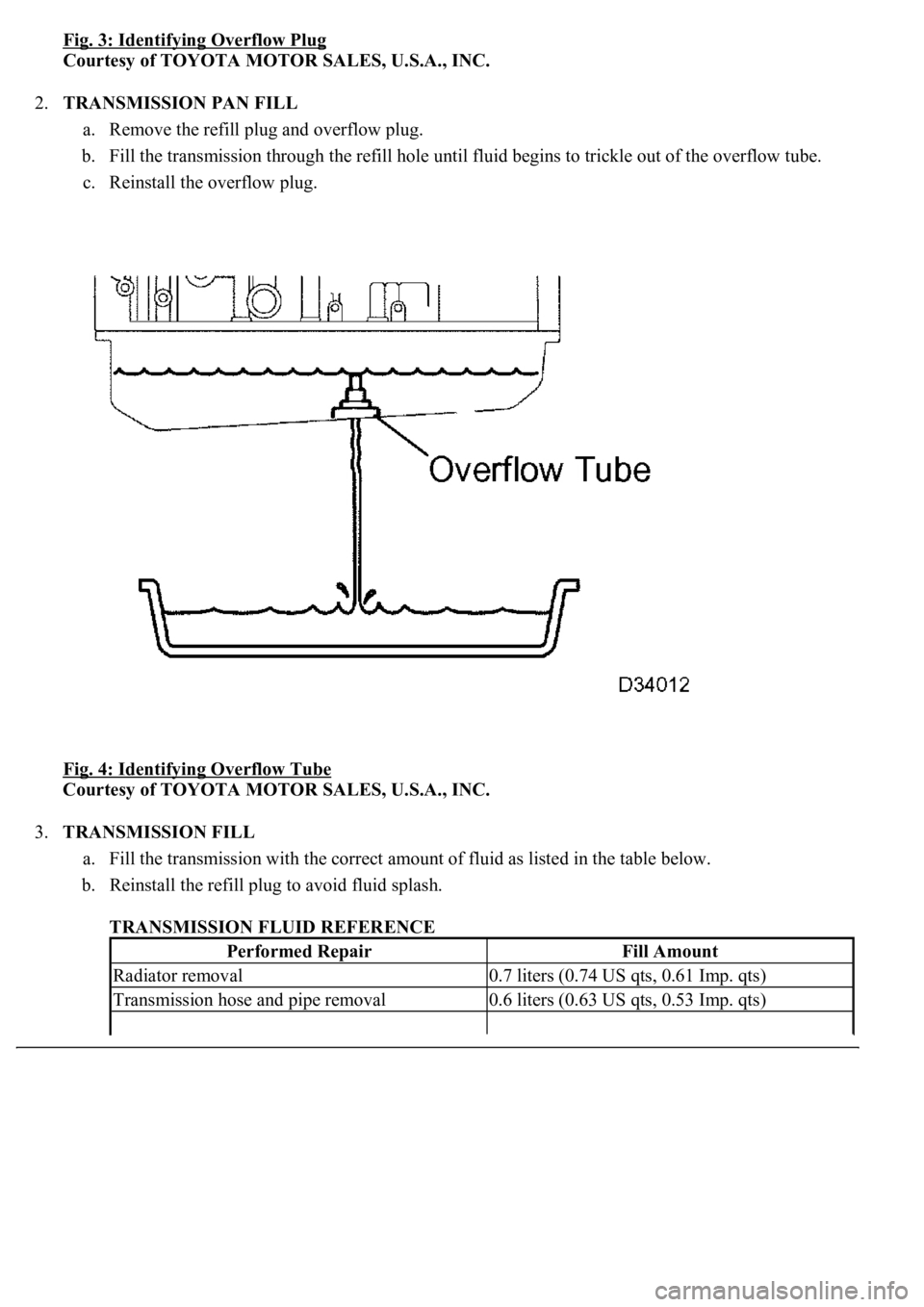
Fig. 3: Identifying Overflow Plug
Courtesy of TOYOTA MOTOR SALES, U.S.A., INC.
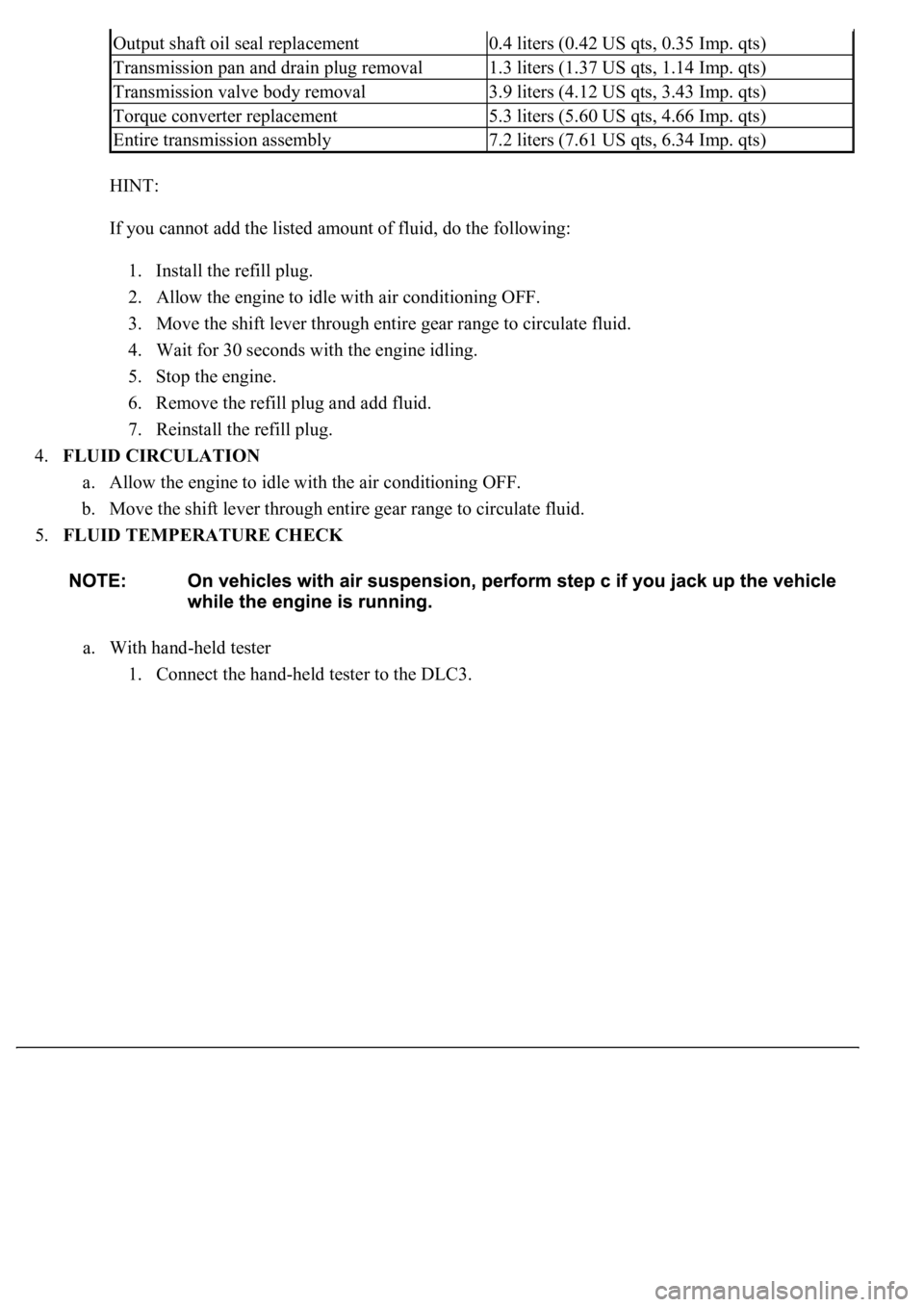
2.TRANSMISSION PAN FILL
a. Remove the refill plug and overflow plug.
b. Fill the transmission through the refill hole until fluid begins to trickle out of the overflow tube.
c. Reinstall the overflow plug.
Fig. 4: Identifying Overflow Tube
Courtesy of TOYOTA MOTOR SALES, U.S.A., INC.
3.TRANSMISSION FILL
a. Fill the transmission with the correct amount of fluid as listed in the table below.
b. Reinstall the refill plug to avoid fluid splash.
TRANSMISSION FLUID REFERENCE
Performed RepairFill Amount
Radiator removal0.7 liters (0.74 US qts, 0.61 Imp. qts)
Transmission hose and pipe removal0.6 liters (0.63 US qts, 0.53 Imp. qts)
Page 822 of 4500
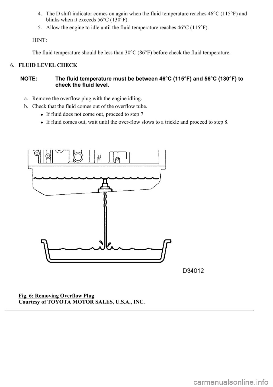
HINT:
If you cannot add the listed amount of fluid, do the following:
1. Install the refill plug.
2. Allow the engine to idle with air conditioning OFF.
3. Move the shift lever through entire gear range to circulate fluid.
4. Wait for 30 seconds with the engine idling.
5. Stop the engine.
6. Remove the refill plug and add fluid.
7. Reinstall the refill plug.
4.FLUID CIRCULATION
a. Allow the engine to idle with the air conditioning OFF.
b. Move the shift lever through entire gear range to circulate fluid.
5.FLUID TEMPERATURE CHECK
a. With hand-held tester
1. Connect the han
d-held tester to the DLC3.
Output shaft oil seal replacement0.4 liters (0.42 US qts, 0.35 Imp. qts)
Transmission pan and drain plug removal1.3 liters (1.37 US qts, 1.14 Imp. qts)
Transmission valve body removal3.9 liters (4.12 US qts, 3.43 Imp. qts)
Torque converter replacement5.3 liters (5.60 US qts, 4.66 Imp. qts)
Entire transmission assembly7.2 liters (7.61 US qts, 6.34 Imp. qts)
Page 823 of 4500
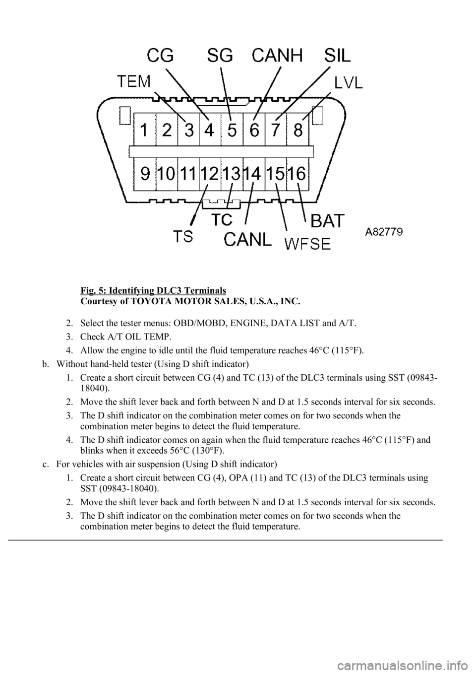
Fig. 5: Identifying DLC3 Terminals
Courtesy of TOYOTA MOTOR SALES, U.S.A., INC.
2. Select the tester menus: OBD/MOBD, ENGINE, DATA LIST and A/T.
3. Check A/T OIL TEMP.
4. Allow the engine to idle until the fluid temperature reaches 46°C (115°F).
b. Without hand-held tester (Using D shift indicator)
1. Create a short circuit between CG (4) and TC (13) of the DLC3 terminals using SST (09843-
18040).
2. Move the shift lever back and forth between N and D at 1.5 seconds interval for six seconds.
3. The D shift indicator on the combination meter comes on for two seconds when the
combination meter begins to detect the fluid temperature.
4. The D shift indicator comes on again when the fluid temperature reaches 46°C (115°F) and
blinks when it exceeds 56°C (130°F).
c. For vehicles with air suspension (Using D shift indicator)
1. Create a short circuit between CG (4), OPA (11) and TC (13) of the DLC3 terminals using
SST (09843-18040).
2. Move the shift lever back and forth between N and D at 1.5 seconds interval for six seconds.
3. The D shift indicator on the combination meter comes on for two seconds when the
combination meter begins to detect the fluid temperature.
Page 824 of 4500
4. The D shift indicator comes on again when the fluid temperature reaches 46°C (115°F) and
blinks when it exceeds 56°C (130°F).
5. Allow the engine to idle until the fluid temperature reaches 46°C (115°F).
HINT:
The fluid temperature should be less than 30°C (86°F) before check the fluid temperature.
6.FLUID LEVEL CHECK
a. Remove the overflow plug with the engine idling.
b. Check that the fluid comes out of the overflow tube.
If fluid does not come out, proceed to step 7
If fluid comes out, wait until the over-flow slows to a trickle and proceed to step 8.
Fig. 6: Removing Overflow Plug
Courtesy of TOYOTA MOTOR SALES, U.S.A., INC.
Page 825 of 4500
7.TRANSMISSION
a. Install the overflow plug.
b. Stop the engine.
c. Remove the refill plug.
d. Add 0.4 liters (0.42 US qts, 0.35 Imp. qts) of fluid.
e. Allow the engine to idle and wait for 10 seconds.
f. Proceed to next step.
8.COMPLETE
a. Install the overflow plug with a new gasket.
b. Stop the engine.
c. Install the refill plug with a new gasket.
d. Install the transmission case cover with the two bolts.
Torque:
20 N.m (204 kgf.cm, 15 ft.lbf) for overflow plug
39 N.m (400 kgf.cm, 53 ft.lbf) for refill plug
REPLACEMENT
1.DISCONNECT BATTERY NEGATIVE TERMINAL
2.REMOVE INSTRUMENT PANEL UNDER COVER SUB-ASSY NO.2 (SEE REPLACEMENT
)
3.REMOVE INSTRUMENT PANEL GARNISH SUB-ASSY LH (SEE REPLACEMENT
)
4.REMOVE INSTRUMENT PANEL FINISH PANEL (SEE REPLACEMENT
)
5.REMOVE INSTRUMENT PANEL UNDER COVER SUB-ASSY NO.1 (SEE REPLACEMENT
)
6.REMOVE SWITCH BRACE HOLE COVER (SEE REPLACEMENT
)
7.REMOVE INSTRUMENT PANEL SAFETY PAD SUB-ASSY NO.1 (SEE REPLACEMENT
)
8.REMOVE INSTRUMENT PANEL CUP HOLDER ASSY (SEE REPLACEMENT
)
9.REMOVE CONSOLE UPPER REAR PANEL SUB-ASSY (SEE REPLACEMENT
)
10.REMOVE CONSOLE BOX CARPET (SEE REPLACEMENT
)
11.REMOVE REAR CONSOLE ARMREST ASSY (SEE REPLACEMENT
)
12.REMOVE INSTRUMENT PANEL FINISH PANEL LOWER CENTER (SEE REPLACEMENT
)
13.REMOVE INSTRUMENT CLUSTER FINISH PANEL SUB-ASSY CENTER (SEE
REPLACEMENT
)
14.REMOVE CONSOLE PANEL SUB-ASSY UPPER (SEE REPLACEMENT
)
15.REMOVE CONSOLE BOX (SEE REPLACEMENT
)
16.SEPARATE OXYGEN SENSOR (SEE REPLACEMENT
)
Page 826 of 4500
17.REMOVE FRONT FLOOR BRACE CENTER (SEE REPLACEMENT )
18.REMOVE EXHAUST PIPE ASSY (SEE REPLACEMENT
)
19.REMOVE FRONT FLOOR HEAT INSULATOR NO.1 (SEE REPLACEMENT
)
20.REMOVE PROPELLER W/CENTER BEARING SHAFT ASSY (SEE OVERHAUL
)
SST 09922-10010
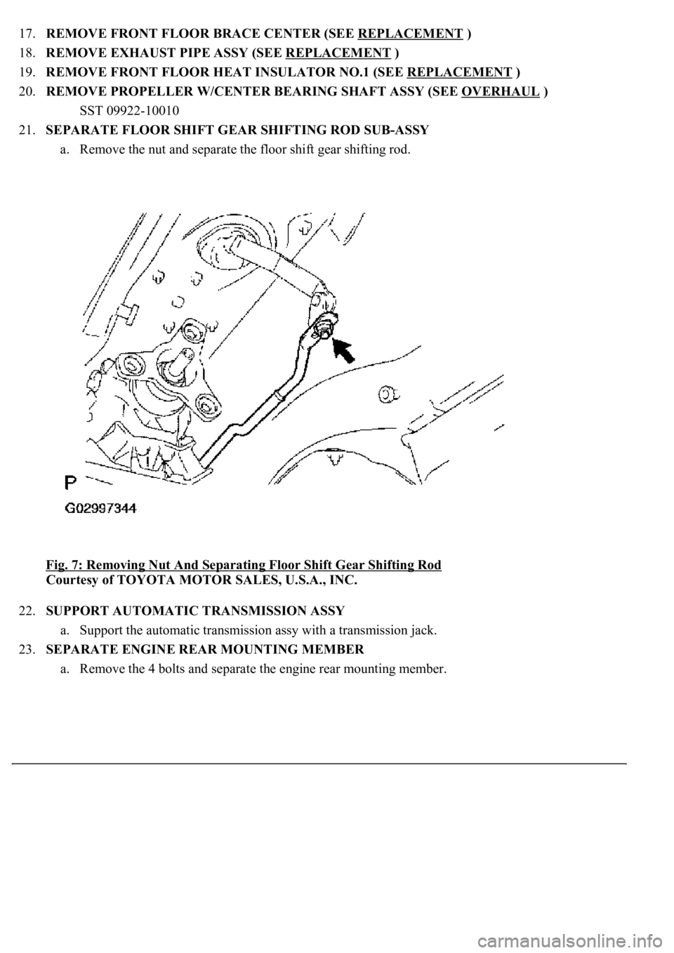
21.SEPARATE FLOOR SHIFT GEAR SHIFTING ROD SUB-ASSY
a. Remove the nut and separate the floor shift gear shifting rod.
Fig. 7: Removing Nut And Separating Floor Shift Gear Shifting Rod
Courtesy of TOYOTA MOTOR SALES, U.S.A., INC.
22.SUPPORT AUTOMATIC TRANSMISSION ASSY
a. Support the automatic transmission assy with a transmission jack.
23.SEPARATE ENGINE REAR MOUNTING MEMBER
a. Remove the 4 bolts and separate the engine rear mounting member.
Page 827 of 4500
Fig. 8: Removing 4 Bolts And Separating Engine Rear Mounting Member
Courtesy of TOYOTA MOTOR SALES, U.S.A., INC.
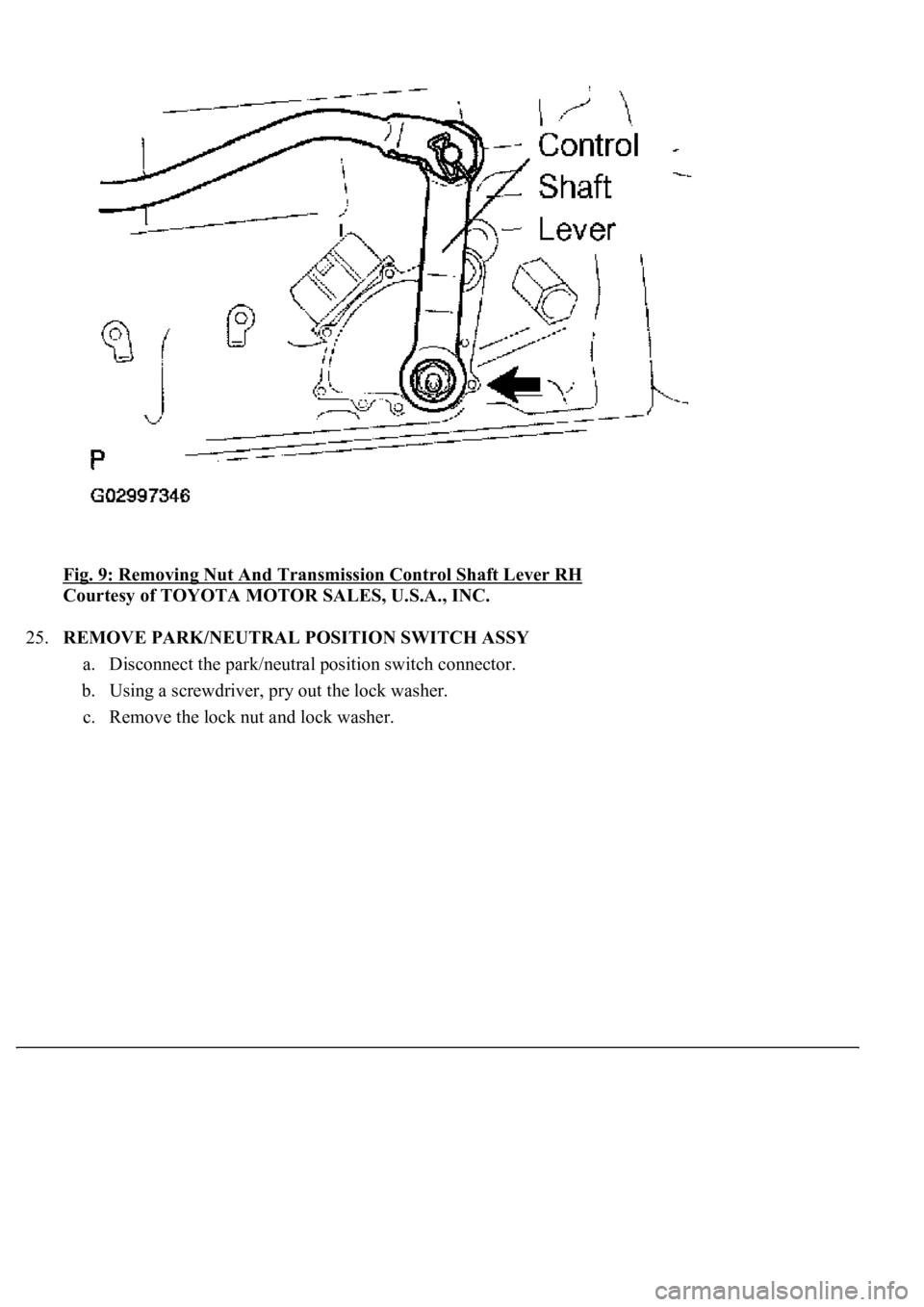
24.REMOVE TRANSMISSION CONTROL SHAFT LEVER RH
a. Remove the nut and transmission control shaft lever RH.
Page 828 of 4500
Fig. 9: Removing Nut And Transmission Control Shaft Lever RH
Courtesy of TOYOTA MOTOR SALES, U.S.A., INC.
25.REMOVE PARK/NEUTRAL POSITION SWITCH ASSY
a. Disconnect the park/neutral position switch connector.
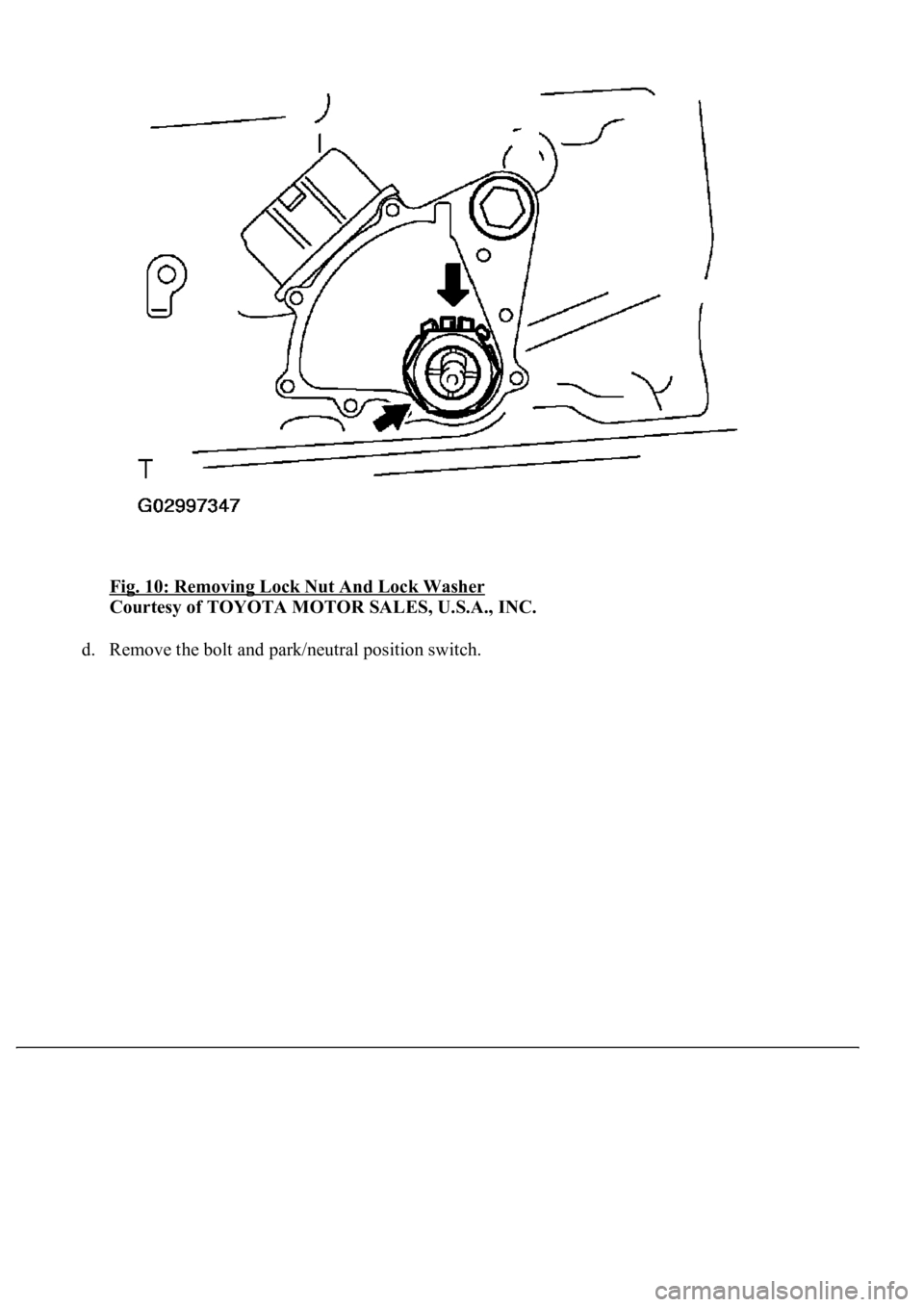
b. Using a screwdriver, pry out the lock washer.
c. Remove the lock nut and lock washer.
Page 829 of 4500
Fig. 10: Removing Lock Nut And Lock Washer
Courtesy of TOYOTA MOTOR SALES, U.S.A., INC.
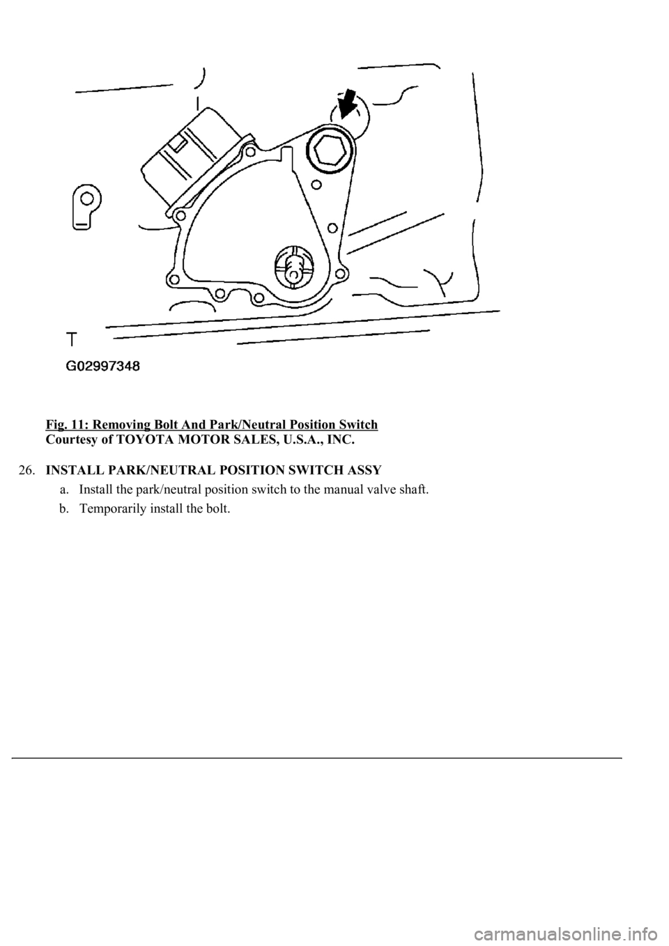
d. Remove the bolt and park/neutral position switch.
Page 830 of 4500
Fig. 11: Removing Bolt And Park/Neutral Position Switch
Courtesy of TOYOTA MOTOR SALES, U.S.A., INC.
26.INSTALL PARK/NEUTRAL POSITION SWITCH ASSY
a. Install the park/neutral position switch to the manual valve shaft.
b. Temporarily install the bolt.
Trending: oil type, Spd, wheel alignment, coolant level, Rear, ground clearance, bulb
