MAZDA 232 1990 Workshop Manual Suplement
Manufacturer: MAZDA, Model Year: 1990, Model line: 232, Model: MAZDA 232 1990Pages: 677, PDF Size: 61.19 MB
Page 111 of 677
Fl FUEL SYSTEM
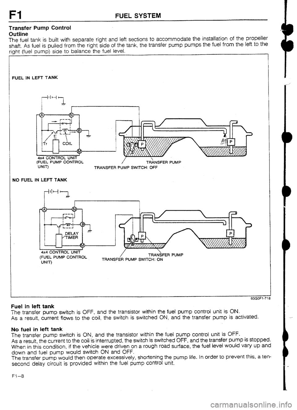
Transfer Pump Csntrol
OutIine
The fuel tank is built with separate right and left sections to accommodate the installation of the propeller
shaft. As fuel is pulled from the right side of the tank, the transfer pump pumps the fuel from the left to the
riuhf (fuel pump) side to balance the fuel level.
FUEL IN 1EFT TANK
4x4 CONTROL UNIT
(FUEL PUMP CONTROL
UNIT)
TRANSFER / TRANSFER PUMP
PUMP SWITCH: OFF
NO FUEL IN LEFT TANK
4x4 CONTROL UNIT
(FUEL PUMP CONTROL
UNIT) / TRAtdFER PUMP
TRANSFER PUMP SWITCH: ON
Fuel in left tank
The transfer pump switch is OFF, and the transistor within the fuel pump control unit is ON.
As a result, current flows to the coil, the switch is switched ON, and the transfer pump is activated.
No fuel in left tank
The transfer pump switch is ON, and the transistor within the fuel pump control unit is OFF.
As a result, the current to the coil is interrupted, the switch
is switched OFF, and the transfer pump is stopped.
When in this condition, if the vehicle were driven on a rough road surface, the fuel level would vary up and
down and fuel pump would switch ON and OFF.
The transfer pump would then operate excessively, shortening the pump life. In order to prevent this, a ten-
second delay circuit is provided within the fuel pump control unit.
Fl-8
Page 112 of 677
SUPPLEMENTAL SERVICE INFORMATION, FUEL SYSTEM Fl
SUPPLEMENTAL SERVICE INFORMATION
The following points in this section are changed in comparison with Mazda 323 Workshop Manuals
(I 203-I U-89F, 1204-I O-89F, I2061 O-89F).
fuel tank
l Removal I Inspection I Installation
4x4 control unit (Fuel pump control unit)
l Inspection procedure added
l Replacement procedure added
Transfer pump switch
l Inspection procedure added
l Replacement procedure added
Transfer pump
l Inspection procedure added
l Replacement procedure added
Exhaust system components
l Removai I Inspection I installation 93GOF? -706
FUELSYSTEM
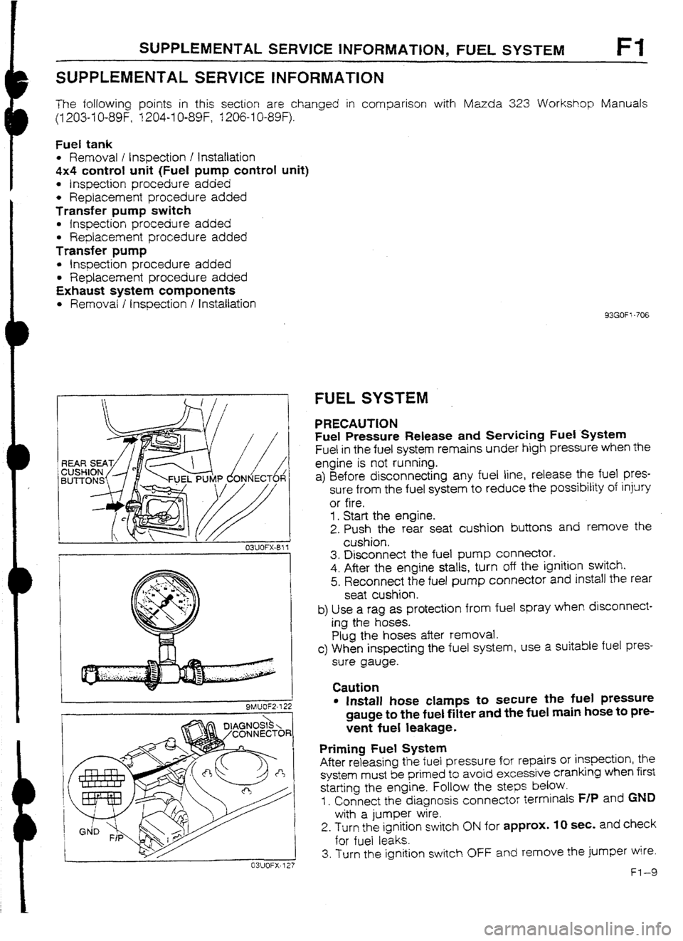
PRECAUTION
Fuel Pressure Release and Sewicing Fuel System
Fuel in the fuel system remains under high pressure when the
engine is not running.
a) Before disconnecting any fuel line, release the fuel
pres-
sure from the fuel system to reduce the possibility of injury
or fire.
1. Start the engine.
2. Push the rear seat cushion buttons and remove the
cushion.
3. Disconnect the fuel pump connector.
4. After the engine stalls, turn off the ignition switch.
5. Reconnect the fuel pump connector and install the rear
seat cushion.
b) Use a rag as protection from fuel spray when disconnect-
ing the hoses.
Plug the hoses after removal.
c> When inspecting the fuel system, use a suitable fuel pres-
sure gauge.
Caution
l Install hose clamps to secure tile fuel pressure
gauge to the fuel filter and the fuel main hose to pre-
vent fuel leakage.
Priming Fuel System
After releasing the fuel pressure for repairs or inspection, the
system must be primed to avoid excessive cranking when first
starting the engine. Follow the
steps below.
I. Connect the diagnosis connector terminals F/P and GND
with a jumper wire.
2. Turn the ignition switch ON for approx. IO sec. and check
for fuel leaks.
3. Turn the ignition switch OFF and remove the jumper wire.
Fl-9
Page 113 of 677
Fl FUEL. SYSTEM
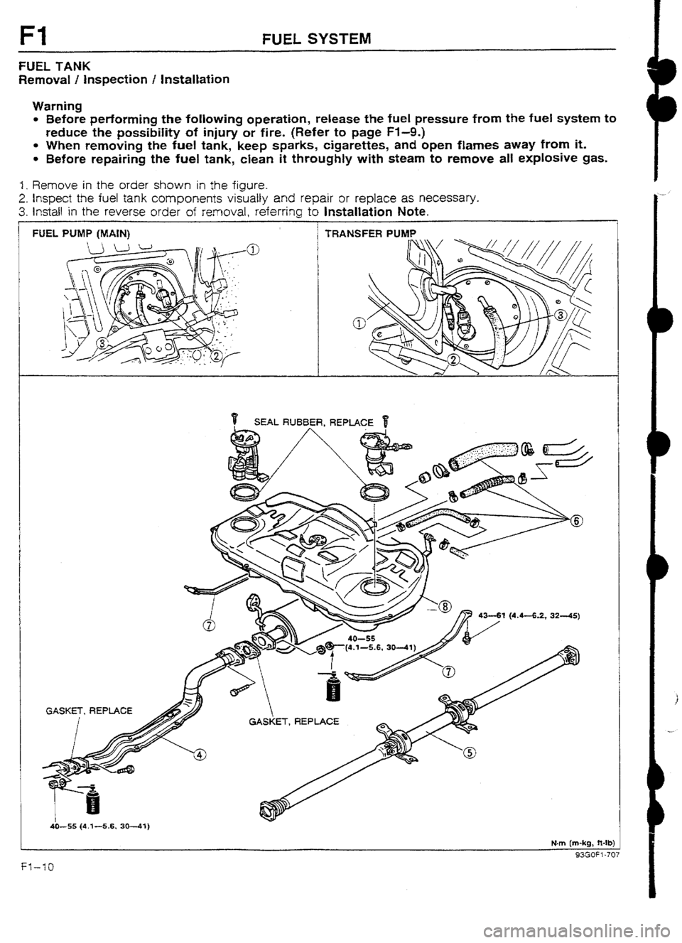
FUEL TANK
Removal / inspection I Installation
Warning
l Before performing the following operation, release the fuel pressure from the fuel system to
reduce the possibiIity of injury or fire. (Refer to page Fl-9.)
l When removing the fuel tank, keep sparks, cigarettes, and open flames away from it.
l Before repairing the fuel tank, clean it throughly with steam to remove all explosive gas.
1. Remove in the order shown in the figure.
2. Inspect the fuel tank components visually and repair or replace as necessary.
3. Install in the reverse order of removal, referring to Installation Note.
FUEL PUMP (MAIN) TRANSFERPU
4341 (4.4-6.2, 3245)
GASKET, REPLACE
ET, REPLACE
4it-55 (4.3 -5.6, 3041)
Nm (m-kg, ft-lb)
a?cnc% .7*7
Page 114 of 677

FUEL SYSTEM, TRANSFER PUMP CONTROL SYSTEM Fl
Note
l Drain the fuel from the fuel tank before removing the tank.
I. Fuel pump cover
2.
Fuel pump connector
3. Fuel hoses
Installation
Note . . . . . . . . . . . . , . . . . . . . . . . . . . . _ . . . . . below
4. Exhaust pipe
Removal / lnstaltatjon . . . . . . . . . . . . .._. page Fl -I 5
5. Propeller shaft
Removal / installation ._..._....,_.._..._.. Section L 6. Fuel fiIler hose, breather hose, and
evaporation
hoses
Installation Note . . . ..*..**......*........~_.....~.
below
7. Fuel tank straps
8. Fuel tank
inspect for cracks and corrosion
93m=: -708
I B FUEL FILLER HOSE
22%
-.
-L
0 F /
@,
M
E -J
03UOFX-Bf 4
93GOFl-709
Installation Note
1. Push the ends of the main fuel hose, fuel return
hose, and
evaporative hoses onto the fuel tank fittings at least 25mm
(1.0 in).
2. Push the fuel filler hose onto the fuel tank pipe
and filler pipe
at ieast 35mm (1.4 in).
TRANSFER PUMP CONTROL SYSTEM
SYSTEM OPERATION ’
1. Turn the ignition switch ON and verify that the fuel
gauge
indicates more than half and that the transfer pump oper-
ating sound is heard.
Warning
l If the fuel level is less than one half, this inspec-
tion cannot be performed.
2. Ground the transfer pump connector terminal-wire (Y/L) with
a jumper wire and verify that the transfer pump stops.
3. Remove the jumper wire and verify that the transfer pump
begins operation after approx. 50 sec.
4. If not as specified, check the following parts.
l 4x4 control unit (Fuel pump control unit).
(Refer to page F-I-1 2.)
l Transfer pump. (Refer to page FI-I 3.)
l Transfer pump switch. (Refer to page Ff -13.)
Page 115 of 677
Fl TRANSFER PUMP CONTROL SYSTEM
93GOFl-7 10
93GOF1-717
93GOf t -7 I
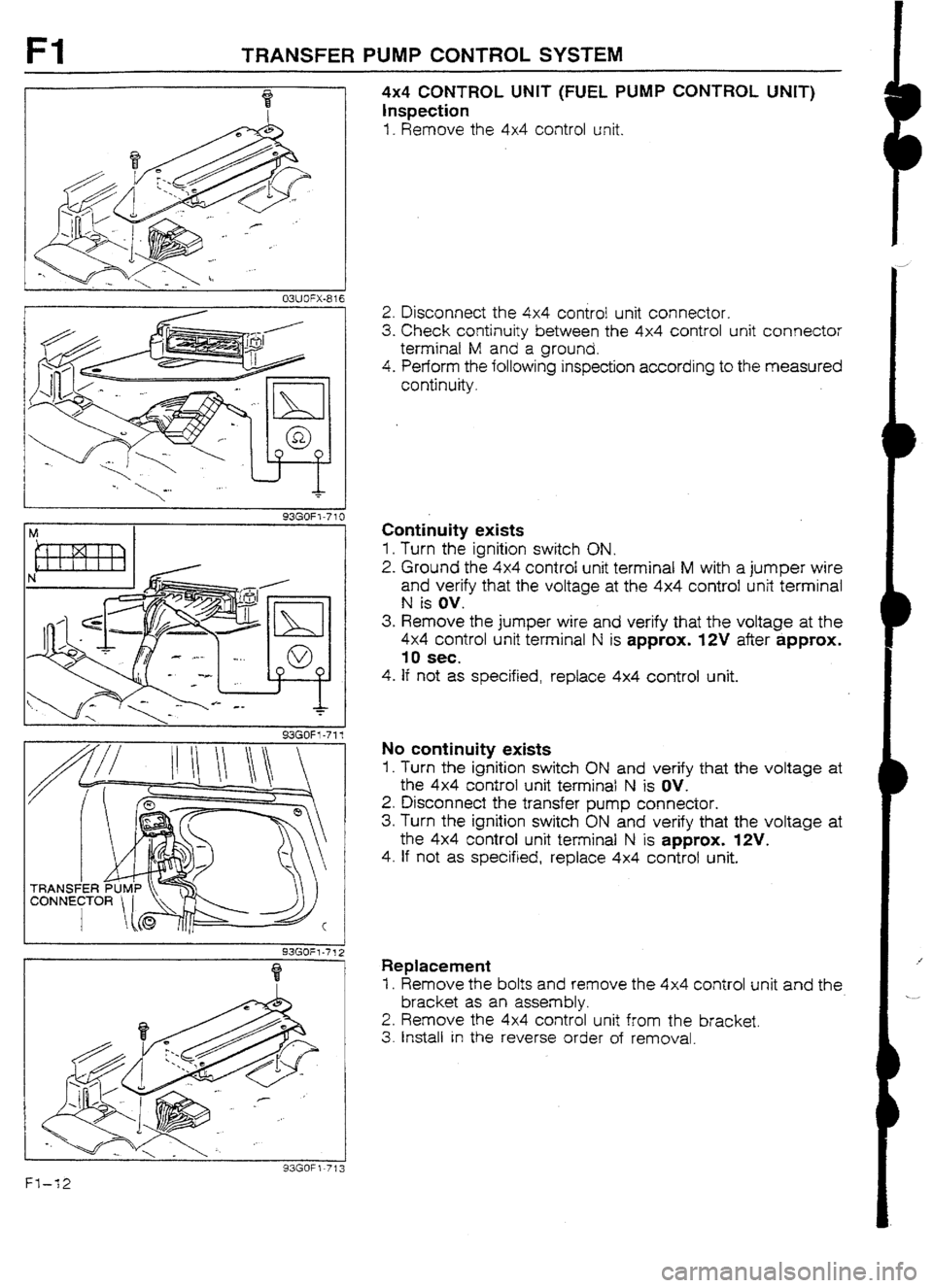
4x4 CONTROL UNIT (FUEL PUMP CONTROL UNIT)
Inspection
I. Remove the 4x4 control unit.
2. Disconnect the 4x4 control unit connector.
3. Check continuity between the 4x4 control unit connector
terminal M and a ground.
4. Perform the following inspection according to the measured
continuity.
Continuity exists
1. Turn the ignition switch ON.
2. Ground the 4x4 control unit terminal M with a jumper wire
and verify that the voltage at the 4x4 control unit terminal
N is ov.
3. Remove the jumper wire and verify that the voltage at the
4x4 control unit terminal N is approx. WV after approx.
10 sec.
4. If not as specified, replace 4x4 control unit.
No continuity exists
1, Turn the ignition switch ON and verify that the voltage at
the 4x4 control unit terminal N is OV.
2. Disconnect the transfer pump connector.
3. Turn the ignition switch ON and verify that the voltage at
the 4x4 control unit terminal N is approx. WV.
4. If not as specified, replace 4x4 control unit.
Replacement
I. Remove the bolts and remove the 4x4 control unit and the
bracket as an assembly.
2. Remove the 4x4 control unit from the bracket.
3. Install in the reverse order of removal.
Fl-12
Page 116 of 677

TRANSFER PUMP CONTROL SYSTEM Fl
TRANSFER PUMP SWITCH
I
93GOF I -7 14
OWOFX-824
TRANSFER PUMP SWITCH
Removal / Installation
.
1. Refer to “Transfer pump replacement”.
(Refer to below.)
inspection
1. Check continuity between transfer pump connector termi-
nal C and ground terminal.
Float position Contrnuity
UD
NO
I Down
I YES I
2. If not as specified, replace the transfer pump switch.
TRANSFER PUMP
Inspection
f . Remove the rear seat cushion.
2. Disconnect the transfer pump connector.
3. Check for continuity between transfer pump connector
terminal-wires (SAW) and (v).
4. If no continuity exists, replace the transfer pump.
Replacement
Warning
l When servicing the fuel system, keep sparks,
cigarettes, and open flames away from the fuel.
1. Remove the rear seat cushion.
FI-13
Page 117 of 677
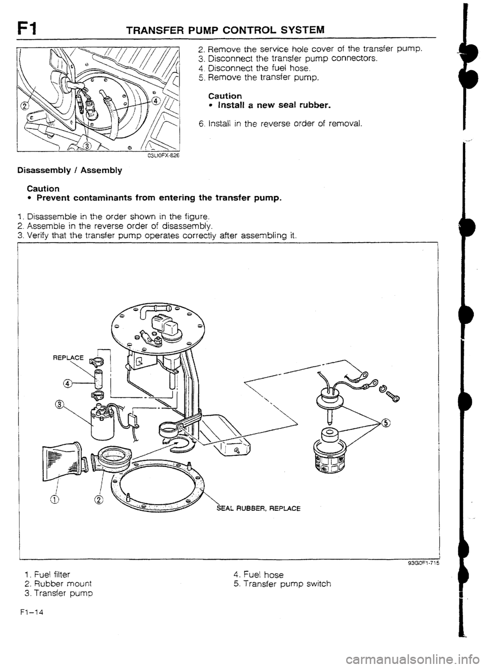
TRANSFER PUMP CONTROL SYSTEM
2. Remove the service hole cover of the transfer pump.
3. Disconnect the transfer pump connectors.
4. Disconnect the fuel hose.
5. Remove the transfer pump.
Caution
l Install a new seal rubber.
6. Install in the reverse order of removal.
03UOFX-626
Disassembly / Assembly
Caution
l Prevent contaminants from entering the transfer pump,
I. Disassemble in the order shown in the figure.
2. Assemble in the reverse order of disassembly.
3. Verify that the transfer pump operates
correctly after assembling it.
EAL RUBBER, REPLACE
1 . Fuel filter
2. Rubber mount
3. Transfer pump 4. Fuel hose
5. Transfer pump
switch
Ft-14
Page 118 of 677
EXHAUST SYSTEM Fl
EXHAUST SYSTEM
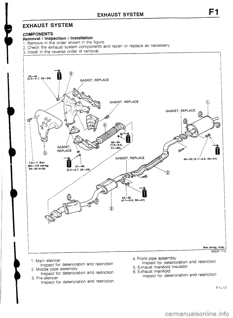
COMPONENTS
Removal I inspection I installation
1. Remove in the order shown in the figure.
2. Check the exhaust system components and repair or replace as necessary.
3. /n-stall in the reverse order of removal.
I
I GASKET, REPLACE
’
f’ GASKET, REPLACE
7.&l? N-m
(80-l 10 cm-kg,
69-95 in-lb)
I {4.1-5.6, 3041)
Nm (m-kg, ft-lb
1. Main silencer
Inspect for deterioration and restriction
2. MiddIe pipe assembly
Inspect for deterioration and restriction
3. Pre-silencer
Inspect for deterioration and restriction 4. Front pipe assembly
Inspect for deterioration and restriction
5. Exhaust manifotd insulator
6. Exhaust manifold
Inspect for deterioration and restriction
Page 119 of 677

Page 120 of 677
F2
FUEL AND EMISSION
CONTROL SYSTEMS
(WITH CATALYTIC CONVERTER)
.
INDEX ..*.........**.*.........*..........*...... F2- 2
OUTLINE ...................................... F2- 4
OUTLINE OF CONSTRUCTION.. .... F2- 4
SYSTEM DIAGRAM ...................... F2- 5
VACUUM HOSE ROUTING
DIAGRAM [BP TURBO] ............... F2- 7
WIRING DlAGRAM.. ..................... FZ- 8
ECU REtATlONSHIP DIAGRAM
[BP TURBO] .............................. F2-10
SPEClFtCATlONS. ........................ F2-11
TURBOCHARGER CONTROL
[BP TURBO] ................................ F2-I 2
OUTLINE .................................... F2-I 2
SYSTEM DIAGRAM ................. .; ... F2-12
WASTEGATE CONTROL ...............
F2-13
FUEL,SYSTEM
.............................. F2-15
OUTLINE
.................................... F2-15
CONSTRUCTlON ......................... F2-15
FUEL VAPOR VALVE ................... F2-16
FUEL PUMP CONTROL SYSTEM.. . F2-16
FUEL PUMP RESISTOR/RELAY ...... F2-18
TRANSFER PUMP CONTROL. ....... F2-I 8
CONTROL SYSTEM ....................... F2-20
STRUCTURAL VIEW.. ................... F2-20
OVERBOOST WARN!NG BUZZER
[BP TURBO] .............................. F2-21
TURBOCI-IARGE INDICATOR
[BP TURBO] .............................. F2-21
KNOCK CONTROL SYSTEM
[BP TURBO] .............................. F2-22
OXYGEN SENSOR [BP TURBO]. .... F2-23
PRESSURE REGULATOR CONTROL
SYSTEM [BP TURBO] ................. F2-23
A/C CUT-OFF SYSTEM (ATX) .........
F2-24 SUPPLEMENTAL SERVICE
INFORMATION ............................. F2-25
SELF-DIAGNOSIS FUNCTION .......... F2-26
OUTLINE
.................................... F2-26
MALFUNCTION CODE NUMBERS . . F2-26
TROUBLESHOOTtNG GUIDE
[BP TURBO1
................................ F2-31
RELATlONSHlP CHART ................ F2-31
SYMPTOM TRUUBLESH0OTlNG .... F2-32
tNTAKE AIR SYSTEM ..................... F2-43
COMPONENTS ............................ F2-43
TURBOCHARGERCONTROL
SYSTEM ...................................... F2-45
PREPARATION ............................ F2-45
SYSTEM OPERATION ................... F2-45
WASTEGATE ............................... F2-45
WASTEGATE SOLENOID VALVE.. .. F2-46
TURBOCHARGER ........................ F2-46
AIR BYPASS VALVE ..................... F2-48
INTERCOOLER ............................ F2-49
FUEL SYSTEM .............................. F2-50
PREPARATION ............................ F2-50
PRECAUTION ............................. F2-50
FUEL TANK
................................ F2-51
TRANSFER PUMP CONTROL
SYSTEM ................................... F2-52
FUEL PUMP CONTROL UNIT ........ F2-53
TRANSFER PUMP SWITCH ........... F2-54
TRANSFER PUMP.. ...................... F2-54
FUEL PUMP RESISTOR/RELAY ...... F2-56
INJECTOR
.................................. F2-56
EXHAUST SYSTEM
COMPONENTS .................................................... ;ff;
CONTROL SYSTEM ....................... F2-59
PREPARATION
............................ F2-59
ENGINE CONTROL UNIT (ECU) ..... F2-59
OXYGEN SENSOR ....................... F2-68
KNOCK SENSOR ......................... F2-69
93GOF2.701