torque MAZDA 6 2002 Suplement User Guide
[x] Cancel search | Manufacturer: MAZDA, Model Year: 2002, Model line: 6, Model: MAZDA 6 2002Pages: 909, PDF Size: 17.16 MB
Page 50 of 909
CYLINDER HEAD GASKET
B2–19
B2
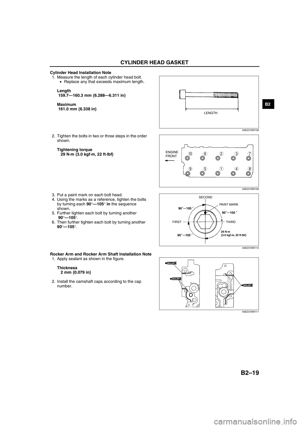
Cylinder Head Installation Note
1. Measure the length of each cylinder head bolt.
•Replace any that exceeds maximum length.
Length
159.7—160.3 mm {6.288—6.311 in}
Maximum
161.0 mm {6.338 in}
2. Tighten the bolts in two or three steps in the order
shown.
Tightening torque
29 N·m {3.0 kgf·m, 22 ft·lbf}
3. Put a paint mark on each bolt head.
4. Using the marks as a reference, tighten the bolts
by turning each 90°—105° in the sequence
shown.
5. Further tighten each bolt by turning another
90°—105°.
6. Then further tighten each bolt by turning another
90°—105°.
Rocker Arm and Rocker Arm Shaft Installation Note
1. Apply sealant as shown in the figure.
Thickness
2 mm {0.079 in}
2. Install the camshaft caps according to the cap
number.
LENGTH
A6E2318W108
98
7
54
3106
1
2ENGINE
FRONT
A6E2318W109
29 N·m
{3.0 kgf·m, 22 ft·lbf}
SECOND
PAINT MARK
FIRST THIRD90 105
90 105
90 105
—
——
A6E2318W110
SEALANTSEALANT
SEALANTSEALANT
SEALANTSEALANT
A6E2318W111
Page 51 of 909
B2–20
CYLINDER HEAD GASKET
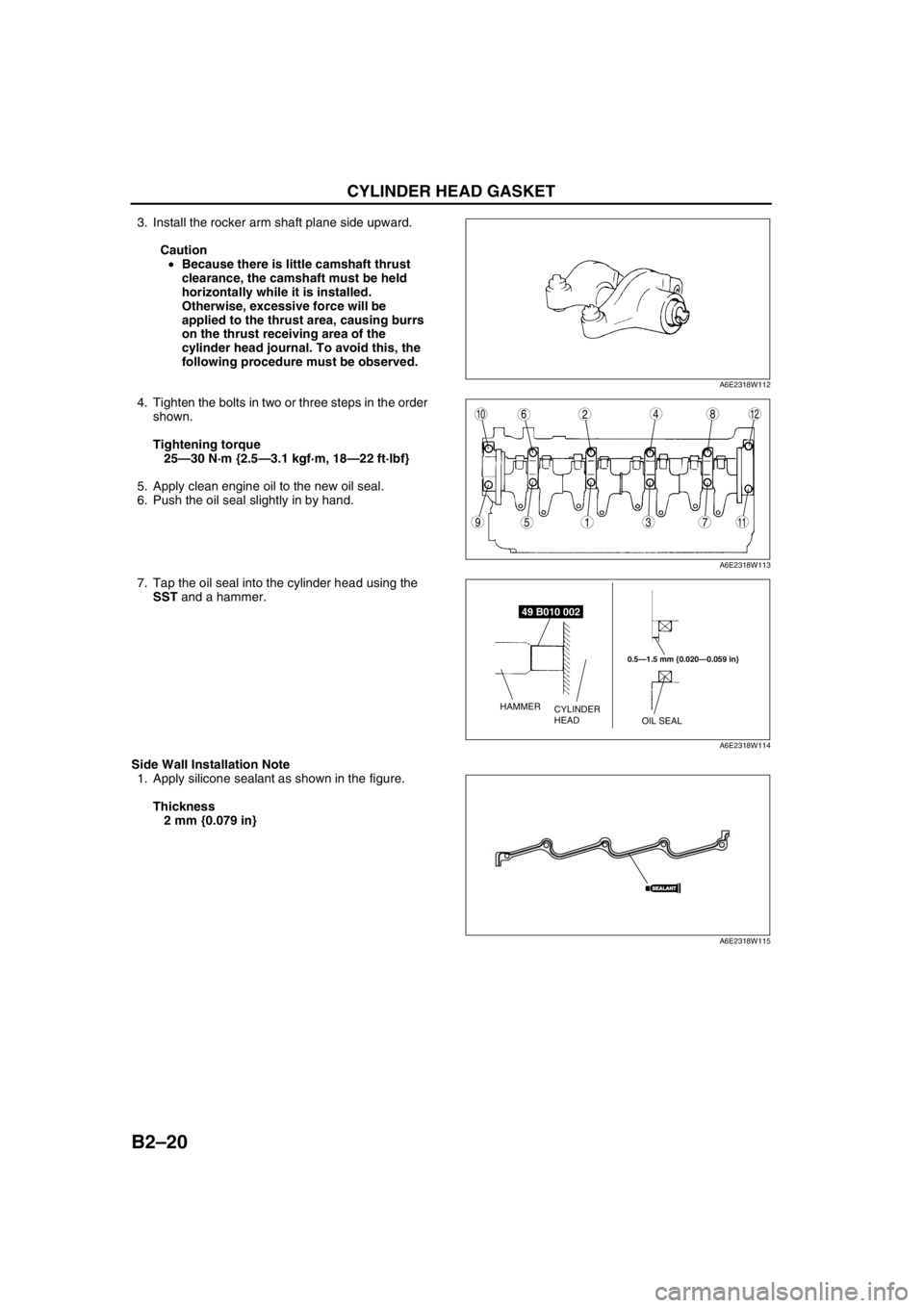
3. Install the rocker arm shaft plane side upward.
Caution
•Because there is little camshaft thrust
clearance, the camshaft must be held
horizontally while it is installed.
Otherwise, excessive force will be
applied to the thrust area, causing burrs
on the thrust receiving area of the
cylinder head journal. To avoid this, the
following procedure must be observed.
4. Tighten the bolts in two or three steps in the order
shown.
Tightening torque
25—30 N·m {2.5—3.1 kgf·m, 18—22 ft·lbf}
5. Apply clean engine oil to the new oil seal.
6. Push the oil seal slightly in by hand.
7. Tap the oil seal into the cylinder head using the
SST and a hammer.
Side Wall Installation Note
1. Apply silicone sealant as shown in the figure.
Thickness
2 mm {0.079 in}
A6E2318W112
9
8
75
4
3
10126
1
2
11
A6E2318W113
49 B010 002
0.5—1.5 mm {0.020—0.059 in}
OIL SEAL CYLINDER
HEAD HAMMER
A6E2318W114
SEALANTSEALANT
A6E2318W115
Page 52 of 909

CYLINDER HEAD GASKET
B2–21
B2
Fuel Injection Pipe Installation Note
Caution
•Fuel injection pipes can be removed and reinstalled up to five times. If removing them for the sixth
time, be sure to replace them with new ones.
Cylinder Head Cover Installation Note
1. Apply silicone sealant to the shaded areas.
Thickness
2 mm {0.079 in}
2. Tighten the bolts in the order shown.
Tightening torque
7.9—10.7 N·m {80—110 kgf·cm, 69.5—95.4
in·lbf}
Seal Plate Installation Note
1. Install the seal plate and hand tighten the bolt in
the order A to B.
2. Tighten the bolts in the order shown.
Tightening torque
7.9—10.7 N·m {80—110 kgf·cm, 69.5—95.4
in·lbf}
Idler Installation Note
Caution
•The idler has a front and back relative to
the engine, therefore when installing
make sure that the longer projection of
the shaft is on the engine side as
indicated in the figure.
SEALANTSEALANTSEALANTSEALANT
SEALANTSEALANT20 mm
{0.79 in}
MIN.VIEW AVIEW A
A6E2318W116
9
8
7
5
4
36
1
2
A6E2318W117
1
2B
A
3
3
A6E2318W118
SHAFTCYLINDER
BLOCK
BOLT
A6E2318W121
Page 53 of 909
B2–22
CYLINDER HEAD GASKET
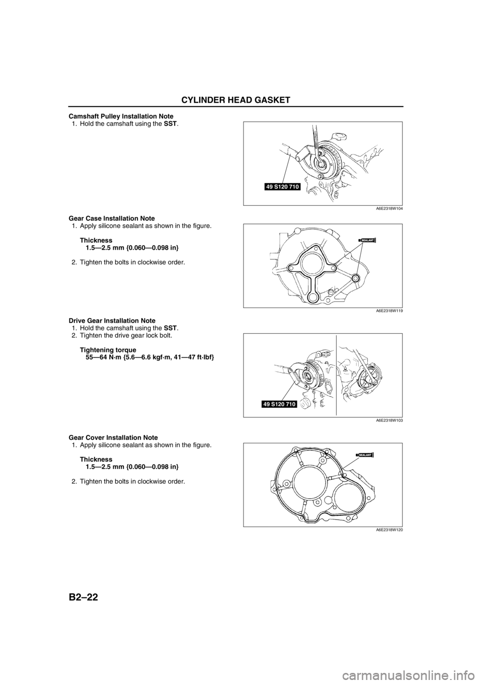
Camshaft Pulley Installation Note
1. Hold the camshaft using the SST.
Gear Case Installation Note
1. Apply silicone sealant as shown in the figure.
Thickness
1.5—2.5 mm {0.060—0.098 in}
2. Tighten the bolts in clockwise order.
Drive Gear Installation Note
1. Hold the camshaft using the SST.
2. Tighten the drive gear lock bolt.
Tightening torque
55—64 N·m {5.6—6.6 kgf·m, 41—47 ft·lbf}
Gear Cover Installation Note
1. Apply silicone sealant as shown in the figure.
Thickness
1.5—2.5 mm {0.060—0.098 in}
2. Tighten the bolts in clockwise order.
49 S120 710
A6E2318W104
SEALANTSEALANT
A6E2318W119
49 S120 710
A6E2318W103
SEALANTSEALANT
A6E2318W120
Page 61 of 909
B2–30
ENGINE
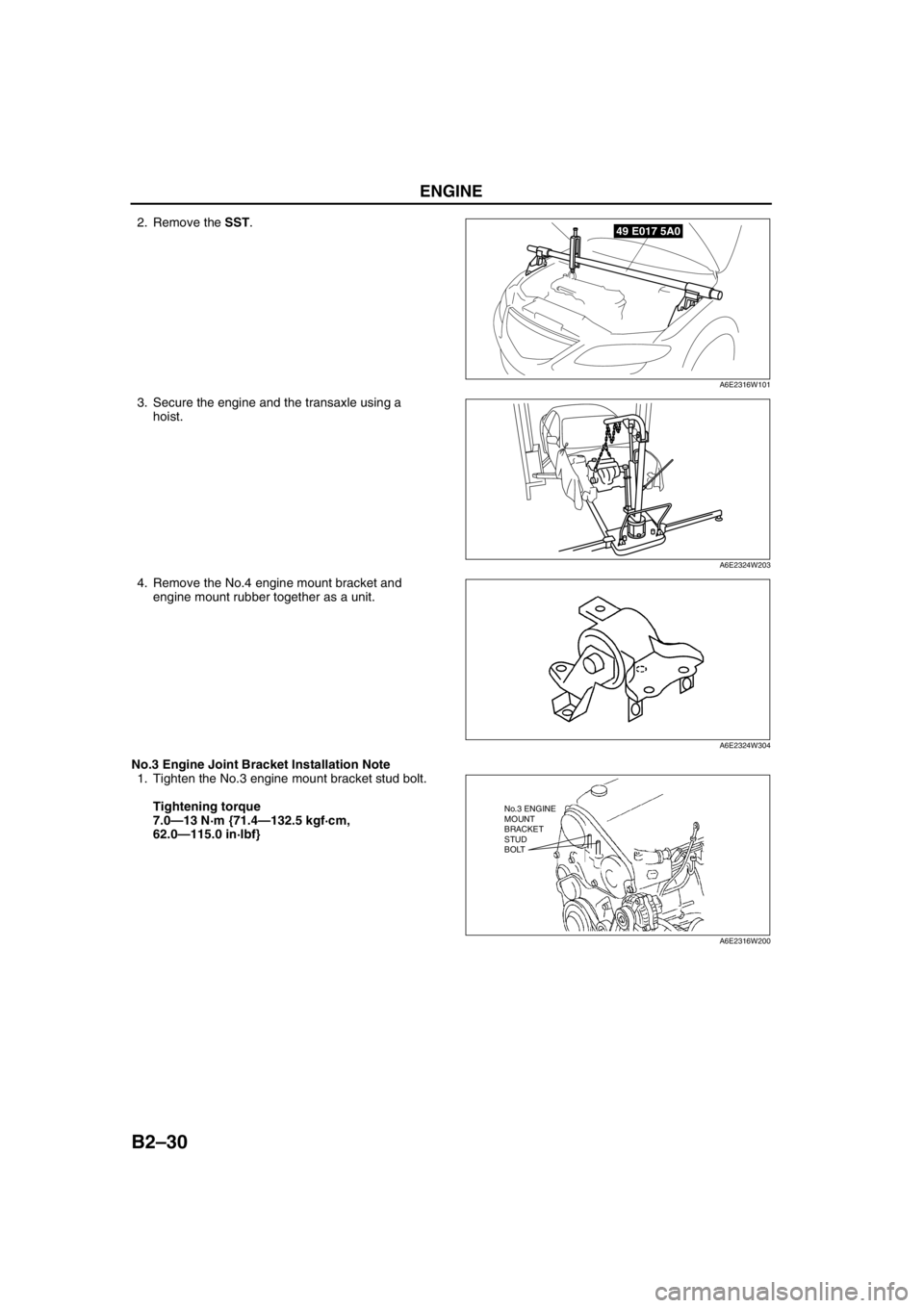
2. Remove the SST.
3. Secure the engine and the transaxle using a
hoist.
4. Remove the No.4 engine mount bracket and
engine mount rubber together as a unit.
No.3 Engine Joint Bracket Installation Note
1. Tighten the No.3 engine mount bracket stud bolt.
Tightening torque
7.0—13 N·m {71.4—132.5 kgf·cm,
62.0—115.0 in·lbf}49 E017 5A0
A6E2316W101
A6E2324W203
A6E2324W304
No.3 ENGINE
MOUNT
BRACKET
STUD
BOLT
A6E2316W200
Page 62 of 909
ENGINE
B2–31
B2
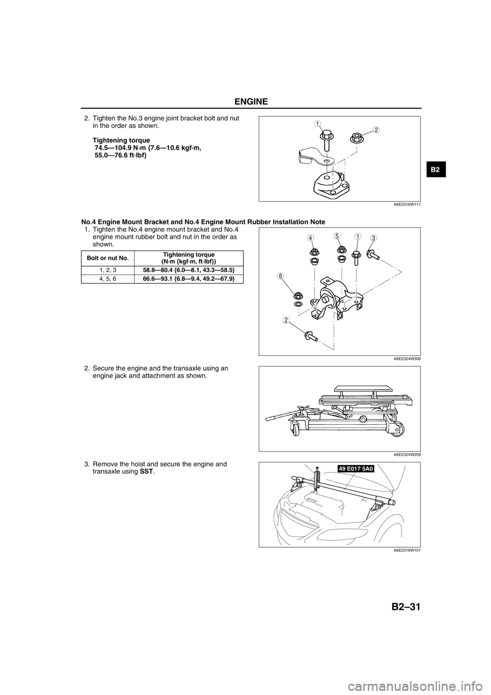
2. Tighten the No.3 engine joint bracket bolt and nut
in the order as shown.
Tightening torque
74.5—104.9 N·m {7.6—10.6 kgf·m,
55.0—76.6 ft·lbf}
No.4 Engine Mount Bracket and No.4 Engine Mount Rubber Installation Note
1. Tighten the No.4 engine mount bracket and No.4
engine mount rubber bolt and nut in the order as
shown.
2. Secure the engine and the transaxle using an
engine jack and attachment as shown.
3. Remove the hoist and secure the engine and
transaxle using SST.12
A6E2316W111
Bolt or nut No.Tightening torque
(N·m {kgf·m, ft·lbf})
1, 2, 358.8—80.4 {6.0—8.1, 43.3—58.5}
4, 5, 666.6—93.1 {6.8—9.4, 49.2—67.9}
5431
2
6
A6E2324W306
A6E2324W209
49 E017 5A0
A6E2316W101
Page 63 of 909
B2–32
ENGINE
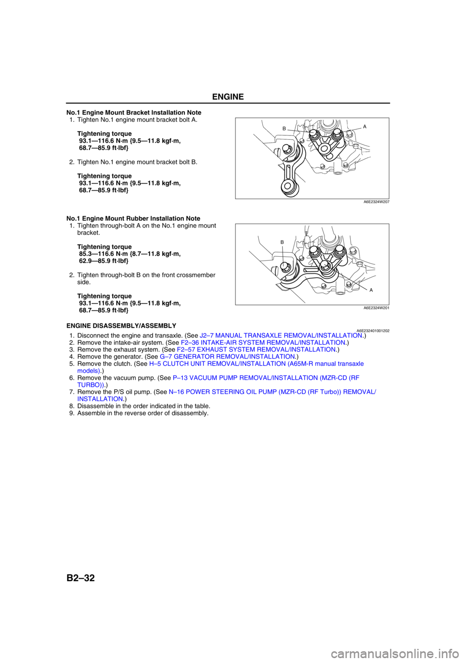
No.1 Engine Mount Bracket Installation Note
1. Tighten No.1 engine mount bracket bolt A.
Tightening torque
93.1—116.6 N·m {9.5—11.8 kgf·m,
68.7—85.9 ft·lbf}
2. Tighten No.1 engine mount bracket bolt B.
Tightening torque
93.1—116.6 N·m {9.5—11.8 kgf·m,
68.7—85.9 ft·lbf}
No.1 Engine Mount Rubber Installation Note
1. Tighten through-bolt A on the No.1 engine mount
bracket.
Tightening torque
85.3—116.6 N·m {8.7—11.8 kgf·m,
62.9—85.9 ft·lbf}
2. Tighten through-bolt B on the front crossmember
side.
Tightening torque
93.1—116.6 N·m {9.5—11.8 kgf·m,
68.7—85.9 ft·lbf}
End Of SieENGINE DISASSEMBLY/ASSEMBLYA6E2324010012021. Disconnect the engine and transaxle. (See J2–7 MANUAL TRANSAXLE REMOVAL/INSTALLATION.)
2. Remove the intake-air system. (See F2–36 INTAKE-AIR SYSTEM REMOVAL/INSTALLATION.)
3. Remove the exhaust system. (See F2–57 EXHAUST SYSTEM REMOVAL/INSTALLATION.)
4. Remove the generator. (See G–7 GENERATOR REMOVAL/INSTALLATION.)
5. Remove the clutch. (See H–5 CLUTCH UNIT REMOVAL/INSTALLATION (A65M-R manual transaxle
models).)
6. Remove the vacuum pump. (See P–13 VACUUM PUMP REMOVAL/INSTALLATION (MZR-CD (RF
TURBO)).)
7. Remove the P/S oil pump. (See N–16 POWER STEERING OIL PUMP (MZR-CD (RF Turbo)) REMOVAL/
INSTALLATION.)
8. Disassemble in the order indicated in the table.
9. Assemble in the reverse order of disassembly.
A
B
A6E2324W207
A B
A6E2324W201
Page 64 of 909

ENGINE
B2–33
B2
.
A/C Compressor Bracket Installation Note
1. Tighten the A/C compressor bracket bolts in the
order shown.
Tightening torque
38—51 N·m {3.8—5.3 kgf·m, 28—38 ft·lbf}
End Of Sie
N·m { kgf·m, ft·lbf} 38—51
{3.8—5.3, 28—38}
1
2
A6E2324W105
1 A/C compressor bracket
(See B2–33 A/C Compressor Bracket Installation
Note)2 Seal plate
43
1
2
A6E2324W106
Page 71 of 909
OIL PRESSURE INSPECTION
D–7
D
OIL PRESSURE INSPECTIONA6E331001003201MZR-CD (RF Turbo)
Warning
•Continuous exposure to USED engine oil has caused skin cancer in laboratory mice. Protect your
skin by washing with soap and water immediately after working with engine oil.
•Hot engines and engine oil can cause severe burns. Turn off the engine and wait until it and the
engine oil have cooled.
1. Disconnect the negative battery cable.
2. Remove the under cover.
3. Remove the oil pressure switch.
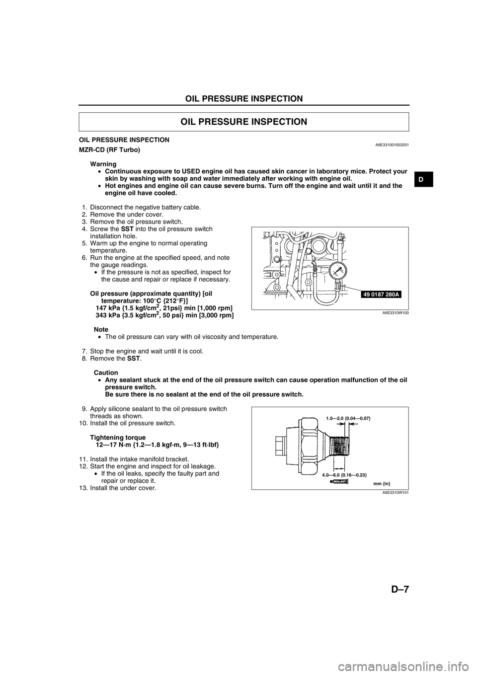
4. Screw the SST into the oil pressure switch
installation hole.
5. Warm up the engine to normal operating
temperature.
6. Run the engine at the specified speed, and note
the gauge readings.
•If the pressure is not as specified, inspect for
the cause and repair or replace if necessary.
Oil pressure (approximate quantity) [oil
temperature: 100°C {212°F}]
147 kPa {1.5 kgf/cm
2, 21psi} min [1,000 rpm]
343 kPa {3.5 kgf/cm2, 50 psi} min [3,000 rpm]
Note
•The oil pressure can vary with oil viscosity and temperature.
7. Stop the engine and wait until it is cool.
8. Remove the SST.
Caution
•Any sealant stuck at the end of the oil pressure switch can cause operation malfunction of the oil
pressure switch.
Be sure there is no sealant at the end of the oil pressure switch.
9. Apply silicone sealant to the oil pressure switch
threads as shown.
10. Install the oil pressure switch.
Tightening torque
12—17 N·m {1.2—1.8 kgf·m, 9—13 ft·lbf}
11. Install the intake manifold bracket.
12. Start the engine and inspect for oil leakage.
•If the oil leaks, specify the faulty part and
repair or replace it.
13. Install the under cover.
End Of Sie
OIL PRESSURE INSPECTION
49 0187 280A
A6E3310W100
1.0—2.0 {0.04—0.07}
4.0—6.0 {0.16—0.23}
mm {in}
SEALANTSEALANT
A6E3310W101
Page 72 of 909
D–8
ENGINE OIL
ENGINE OIL INSPECTIONA6E331214001201MZR-CD (RF Turbo)
1. Position the vehicle on level ground.
2. Warm up the engine to normal operating temperature.
3. Stop the engine and wait for 5 min.
4. Verify that the oil level is between the L and F marks on the dipstick and check the engine oil condition.
•If the oil level is below the L mark, add engine oil. (See D–8 ENGINE OIL REPLACEMENT.)
End Of SieENGINE OIL REPLACEMENTA6E331214001202MZR-CD (RF Turbo)
Warning
•Hot engines and engine oil can cause severe burns. Turn off the engine and wait until it and the
engine oil have cooled.
•A vehicle that is lifted but not securely supported on safety stands is dangerous. It can slip or fall,
causing death or serious injury. Never work around or under a lifted vehicle if it is not securely
supported on safety stands.
•Continuous exposure to USED engine oil has caused skin cancer in laboratory mice. Protect your
skin by washing with soap and water immediately after working with engine oil.
Caution
•In case you spill engine oil on the front pipe, wipe it off completely. If you fail to wipe the spilled
oil, it will produce fumes because of the heat.
1. Position the vehicle on level ground.
2. Remove the the oil filler cap.
3. Remove the under cover.
4. Remove the oil pan drain plug.
5. Drain the engine oil into a container.
6. Install the oil pan drain plug with a new the washer.
Tightening torque
12—17 N·m {1.2—1.8 kgf·m, 9—13 ft·lbf}
Note
•The amount of residual oil in the engine can vary with the replacement method, oil temperature, etc. Verify
the oil level after engine oil replacement.
7. Refill the engine oil with the specified type and amount, then install the oil filler cap.
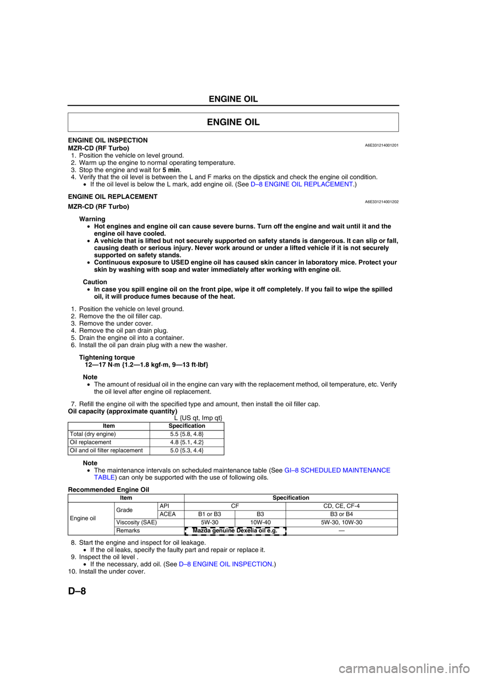
Oil capacity (approximate quantity)
L {US qt, Imp qt}
Note
•The maintenance intervals on scheduled maintenance table (See GI–8 SCHEDULED MAINTENANCE
TABLE) can only be supported with the use of following oils.
Recommended Engine Oil
8. Start the engine and inspect for oil leakage.
•If the oil leaks, specify the faulty part and repair or replace it.
9. Inspect the oil level .
•If the necessary, add oil. (See D–8 ENGINE OIL INSPECTION.)
10. Install the under cover.
End Of Sie
ENGINE OIL
Item Specification
Total (dry engine) 5.5 {5.8, 4.8}
Oil replacement 4.8 {5.1, 4.2}
Oil and oil filter replacement 5.0 {5.3, 4.4}
Item Specification
Engine oil GradeAPI CF CD, CE, CF-4
ACEA B1 or B3 B3 B3 or B4
Viscosity (SAE) 5W-30 10W-40 5W-30, 10W-30
RemarksMazda genuine Dexelia oil e.g. —