torque MAZDA 6 2002 Suplement Repair Manual
[x] Cancel search | Manufacturer: MAZDA, Model Year: 2002, Model line: 6, Model: MAZDA 6 2002Pages: 909, PDF Size: 17.16 MB
Page 488 of 909
AUTOMATIC TRANSAXLE
K2–73
K2
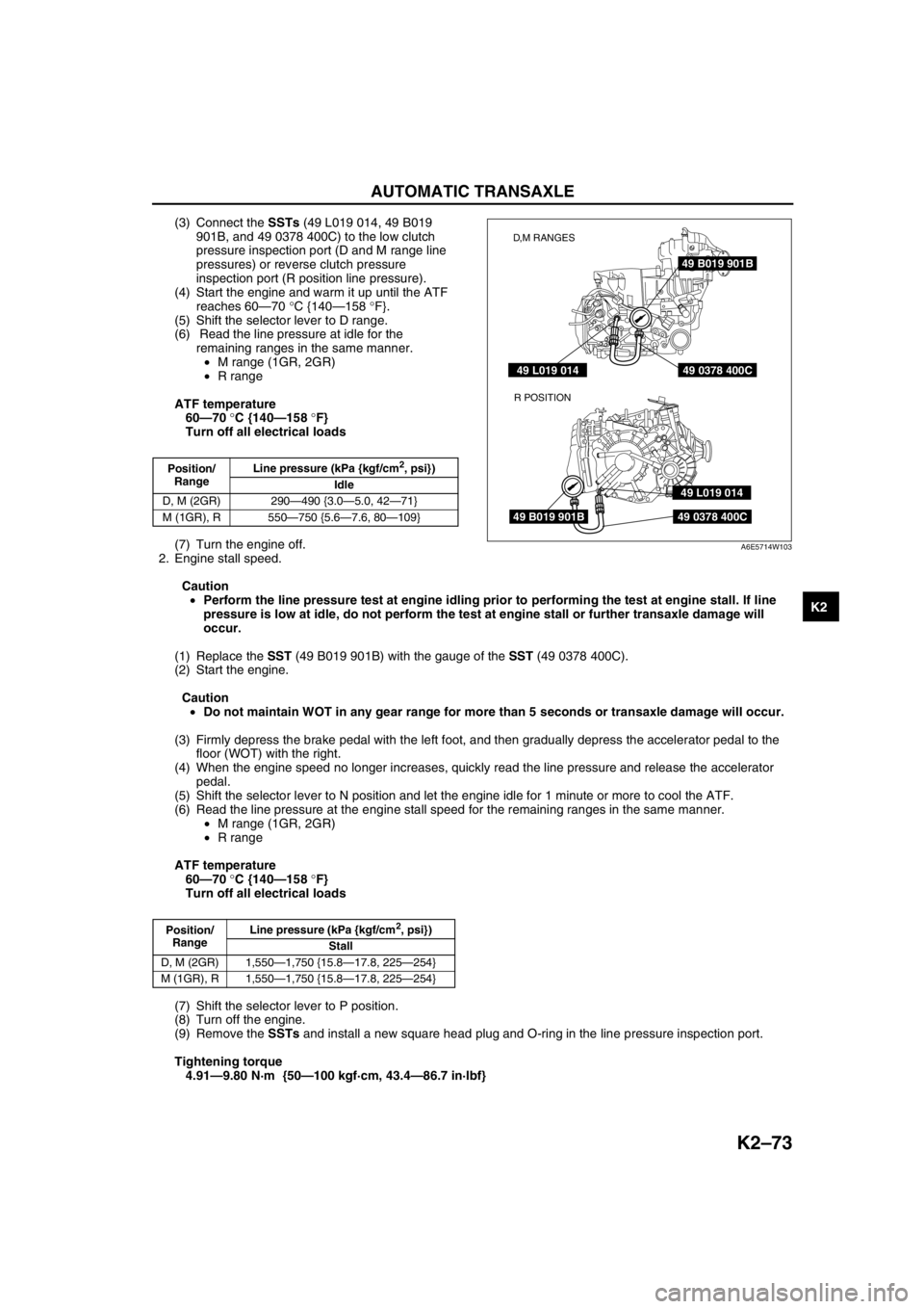
(3) Connect the SSTs (49 L019 014, 49 B019
901B, and 49 0378 400C) to the low clutch
pressure inspection port (D and M range line
pressures) or reverse clutch pressure
inspection port (R position line pressure).
(4) Start the engine and warm it up until the ATF
reaches 60—70 °C {140—158 °F}.
(5) Shift the selector lever to D range.
(6) Read the line pressure at idle for the
remaining ranges in the same manner.
•M range (1GR, 2GR)
•R range
ATF temperature
60—70 °C {140—158 °F}
Turn off all electrical loads
(7) Turn the engine off.
2. Engine stall speed.
Caution
•Perform the line pressure test at engine idling prior to performing the test at engine stall. If line
pressure is low at idle, do not perform the test at engine stall or further transaxle damage will
occur.
(1) Replace the SST (49 B019 901B) with the gauge of the SST (49 0378 400C).
(2) Start the engine.
Caution
•Do not maintain WOT in any gear range for more than 5 seconds or transaxle damage will occur.
(3) Firmly depress the brake pedal with the left foot, and then gradually depress the accelerator pedal to the
floor (WOT) with the right.
(4) When the engine speed no longer increases, quickly read the line pressure and release the accelerator
pedal.
(5) Shift the selector lever to N position and let the engine idle for 1 minute or more to cool the ATF.
(6) Read the line pressure at the engine stall speed for the remaining ranges in the same manner.
•M range (1GR, 2GR)
•R range
ATF temperature
60—70 °C {140—158 °F}
Turn off all electrical loads
(7) Shift the selector lever to P position.
(8) Turn off the engine.
(9) Remove the SSTs and install a new square head plug and O-ring in the line pressure inspection port.
Tightening torque
4.91—9.80 N·m {50—100 kgf·cm, 43.4—86.7 in·lbf}
Position/
RangeLine pressure (kPa {kgf/cm2, psi})
Idle
D, M (2GR) 290—490 {3.0—5.0, 42—71}
M (1GR), R 550—750 {5.6—7.6, 80—109}
Position/
RangeLine pressure (kPa {kgf/cm
2, psi})
Stall
D, M (2GR) 1,550—1,750 {15.8—17.8, 225—254}
M (1GR), R 1,550—1,750 {15.8—17.8, 225—254}
49 B019 901B
49 0378 400C
49 0378 400C
49 L019 014
49 L019 014
49 B019 901B
D,M RANGES
R POSITION
A6E5714W103
Page 489 of 909

K2–74
AUTOMATIC TRANSAXLE
Evaluation of line pressure test
Stall Speed Test
1. Perform mechanical system test preparation. (See K2–72 Mechanical System Test Preparation.)
2. Connect a tachometer.
3. Start the engine.
4. Shift the selector lever to D range.
Caution
•Do not maintain WOT in any gear range for more than 5 seconds or transaxle damage will occur.
•If engine speed recorded by the tachometer exceeds maximum specified rpm, release the
accelerator pedal immediately. Clutch or band slippage is indicator.
5. Firmly depress the brake pedal with the left foot, and gently depress the accelerator pedal to the floor (WOT)
with the right.
6. When the engine speed no longer increases, quickly read the engine speed and release the accelerator pedal.
7. Shift the selector the to N position and let the engine idle for 1 minute or more to cool the ATF.
8. Perform stall tests for the remaining ranges and position in the same manner.
•R position
•Mrange (1GR, 2GR)
Engine stall speed
ATF temperature : 60—70 °C {140—158 °F}
Turn off all electrical loads
2,200—2,600 rpm
9. Turn off the engine.
Evaluation of stall test
Condition Possible cause
IdleBelow specificationLow pressure in all rangesWorn oil pump
Poor operation of each solenoid
Fluid leaking from oil strainer, oil pump, pressure regulator
valve, torque converter relief valve, and/or pressure relief valve
Pressure regulator valve or pilot valve sticking
Damaged pressure regulator valve spring or pilot valve spring
Low pressure in D and M
rangeFluid leaking from hydraulic circuit of low clutch
Low pressure in R position
onlyFluid leaking from hydraulic circuit of reverse clutch
Fluid leaking from hydraulic circuit of low and reverse brake
clutch
Above specification High pressure in all rangesThrottle position sensor out of adjustment
TFT sensor malfunction
Poor operation of shift solenoid
Pilot valve sticking
Pressure reducing valve or plug sticking
Stall Below specification Low pressure in all rangesThrottle position sensor out of adjustment
Pressure control solenoid malfunction
Poor operation of shift solenoid
Pilot valve sticking
Pressure reducing valve or plug sticking
Condition Possible cause
Above specificationIn all forward ranges and R
positionInsufficient line pressure
Worm oil pump
Poor operation of low clutch
Poor adjustment or malfunction of TR switch
Oil leaking from oil pump, control valve, and/or transmission
case
Pressure regulator valve or pilot valve sticking
In all forward ranges Low clutch slippage
Low one-way clutch slippage
Reduction one-way clutch slippage
In R positionLow and reverse brake slippage
Reverse clutch slippage
Reduction brake slippage
Below specificationIn all forward ranges and R
positionEngine out of tune
One-way clutch slippage within torque converter
Page 492 of 909
AUTOMATIC TRANSAXLE
K2–77
K2
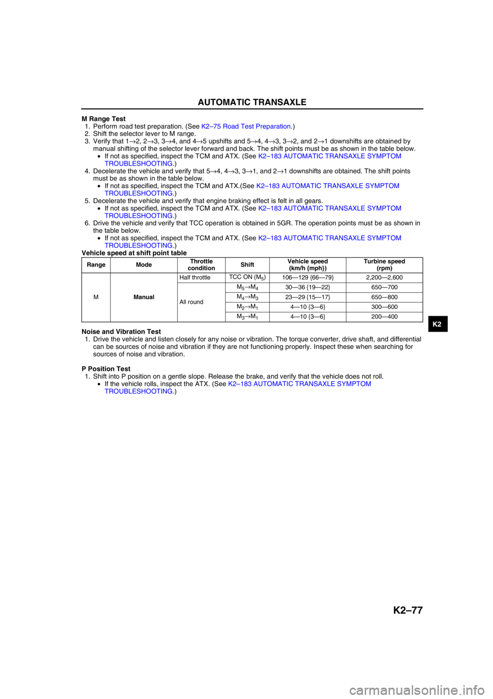
M Range Test
1. Perform road test preparation. (See K2–75 Road Test Preparation.)
2. Shift the selector lever to M range.
3. Verify that 1→2, 2→3, 3→4, and 4→5 upshifts and 5→4, 4→3, 3→2, and 2→1 downshifts are obtained by
manual shifting of the selector lever forward and back. The shift points must be as shown in the table below.
•If not as specified, inspect the TCM and ATX. (See K2–183 AUTOMATIC TRANSAXLE SYMPTOM
TROUBLESHOOTING.)
4. Decelerate the vehicle and verify that 5→4, 4→3, 3→1, and 2→1 downshifts are obtained. The shift points
must be as shown in the table below.
•If not as specified, inspect the TCM and ATX.(See K2–183 AUTOMATIC TRANSAXLE SYMPTOM
TROUBLESHOOTING.)
5. Decelerate the vehicle and verify that engine braking effect is felt in all gears.
•If not as specified, inspect the TCM and ATX. (See K2–183 AUTOMATIC TRANSAXLE SYMPTOM
TROUBLESHOOTING.)
6. Drive the vehicle and verify that TCC operation is obtained in 5GR. The operation points must be as shown in
the table below.
•If not as specified, inspect the TCM and ATX. (See K2–183 AUTOMATIC TRANSAXLE SYMPTOM
TROUBLESHOOTING.)
Vehicle speed at shift point table
Noise and Vibration Test
1. Drive the vehicle and listen closely for any noise or vibration. The torque converter, drive shaft, and differential
can be sources of noise and vibration if they are not functioning properly. Inspect these when searching for
sources of noise and vibration.
P Position Test
1. Shift into P position on a gentle slope. Release the brake, and verify that the vehicle does not roll.
•If the vehicle rolls, inspect the ATX. (See K2–183 AUTOMATIC TRANSAXLE SYMPTOM
TROUBLESHOOTING.)
Range ModeThrottle
conditionShiftVehicle speed
(km/h {mph})Turbine speed
(rpm)
MManualHalf throttleTCC ON (M
5)
106—129 {66—79} 2,200—2,600
All roundM
5→M430—36 {19—22} 650—700
M
4→M323—29 {15—17} 650—800
M
2→M14—10 {3—6} 300—600
M
3→M14—10 {3—6} 200—400
Page 493 of 909

K2–78
AUTOMATIC TRANSAXLE
Evaluation
End Of SieAUTOMATIC TRANSAXLE FLUID (ATF) INSPECTIONA6E571419001201Automatic Transaxle Fluid (ATF) Condition Inspection
1. One way of determining whether the transaxle should be replaced is by noting:
•If the ATF is muddy or varnished.
•If the ATF smells strange or unusual.
ATF Condition
Condition Possible Cause
No 1-2 up- or downshiftStuck shift solenoid C
Stuck shift valve C
Wore 2-4 brake
Trouble intermediate sensor
No 2-3 up- or downshiftStuck shift solenoid A
Stuck shift valve A
Wore high clutch
No 3-4 up- or downshiftStuck shift solenoid B
Stuck shift valve B
Wore 2-4 brake
No 4-5 up- or downshiftStuck shift solenoid A
Stuck shift valve A
Wore direct clutch
Trouble TFT
TCC non operation shiftStuck TCC solenoid valve
Stuck TCC valve
Incorrect shift pointTrouble VSS output signal
Trouble TR switch
Trouble TP signal and engine torque signal
Excessive shift shock slippageStuck pressure control solenoid
Stuck pressure regulator valve
Stuck pressure modifier valve
Stuck accumulator valve A, B, or C
Stuck 2-4 brake solenoid valve
Stuck high clutch solenoid valve
Stuck low clutch accumulator
Stuck 2-4 brake accumlator
Stuck high clutch accumlator
Stuck direct clutch accumlator
Stuck reduction accumlator
Trouble VSS
No Engine braking effect Wore reduction brake band
Stuck reduction reducing valve
Stuck reduction timing valve
Stuck reduction timing solenoid valve
Condition Possible cause
Clear dark red Normal—
Light red (pink) Contaminated with water•Broken oil cooler inside of radiator
•Poor filler tube installation:
Problem could be occurring to parts inside the
transaxle by water contamination. If necessary,
exchange transaxle.
Reddish
brownHas burnt smell and metal
specs are foundDeteriorated ATFDefect powertrain components inside of transaxle:
Specks cause wide range of problems by plugging up
in oil pipe, control valve body and oil cooler in radiator.
•When large amount of metal specks are found.
Exchange transaxle if necessary.
•Implement flushing operation as there is a
possibility to have specks plugging up oil pipe and/
or oil cooler inside of radiator.
Has no burnt smell Normal•Discoloration by oxidation
Page 494 of 909
AUTOMATIC TRANSAXLE
K2–79
K2
Automatic Transaxle Fluid (ATF) Level Inspection
Caution
•The ATF amount varies according to ATF's temperature. Therefore, when checking the ATF level or
replacing the ATF, use a thermometer to measure the temperature then adjust the ATF amount to
the specified level according to the specified temperature.
1. Park the vehicle on level ground.
2. Apply the parking brake and position wheel chocks securely to prevent the vehicle from rolling.
3. Adjust the length of the thermistor probe measure to the measure same as the dipstick and hold the probe with
a paper holder.
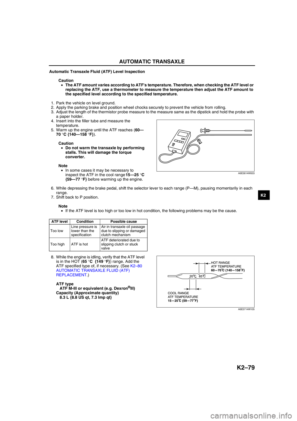
4. Insert into the filler tube and measure the
temperature.
5. Warm up the engine until the ATF reaches (60—
70 °C {140—158 °F}).
Caution
•Do not warm the transaxle by performing
stalls. This will damage the torque
converter.
Note
•In some cases it may be necessary to
inspect the ATF in the cool range 15—25 °C
{59—77 °F} before warming up the engine.
6. While depressing the brake pedal, shift the selector lever to each range (P—M), pausing momentarily in each
range.
7. Shift back to P position.
Note
•If the ATF level is too high or too low in hot condition, the following problems may be the cause.
8. While the engine is idling, verify that the ATF level
is in the HOT (65 °C {149 °F}) range. Add the
ATF specified type of, if necessary. (See K2–80
AUTOMATIC TRANSAXLE FLUID (ATF)
REPLACEMENT.)
ATF type
ATF M-III or equivalent (e.g. Dexron
®III)
Capacity (Approximate quantity)
8.3 L {8.8 US qt, 7.3 Imp qt}
End Of Sie
ATF level Condition Possible cause
Too lowLine pressure is
lower than the
specificationAir in transaxle oil passage
due to slipping or damaged
clutch mechanism
Too high ATF is hotATF deteriorated due to
slipping clutch or stuck
valve
A6E5614W003
A6E5714W105
Page 495 of 909
K2–80
AUTOMATIC TRANSAXLE
AUTOMATIC TRANSAXLE FLUID (ATF) REPLACEMENTA6E571419001202
Warning
•When the transaxle and ATF are hot, they can badly burn you. Turn off the engine and wait until
they are cool before changing the ATF.
1. Remove the oil dipstick.
2. Remove the oil drain plug and washer.
3. Drain the ATF into a container.
4. Install a new washer and the drain plug.
Tightening torque
39—54 N·m {3.9—5.6 kgf·m, 29—40 ft·lbf}
5. Add the specified type of ATF through the oil filler
tube, until ATF level reaches lower notch of
dipstick.
ATF type
ATF M-III or equivalent (e.g. Dexron
®III)
Capacity (Approximate quantity)
8.3 L {8.8 US qt, 7.3 Imp qt}
6. Verify that the ATF level is in the HOT (65 °C {149 °F}) range.
•Add ATF to the specified level as necessary.
End Of Sie
TRANSAXLE RANGE (TR) SWITCH INSPECTIONA6E571419440201
Note
•Input signals of the TR switch can be inspected with a WDS or equivalent. (See K2–90 TCM
INSPECTION.)
Inspection of Operation
1. Verify that the starter operates only with the ignition switch at the START position and the selector lever in P
and N positions.
•If not as specified, inspect for continuity at the TR switch. (See K2–80 Inspection of Continuity.)
2. Verify that the back-up lights illuminate when shifted to R position with the ignition switch at the ON position.
•If not as specified, inspect for continuity at the TR switch.
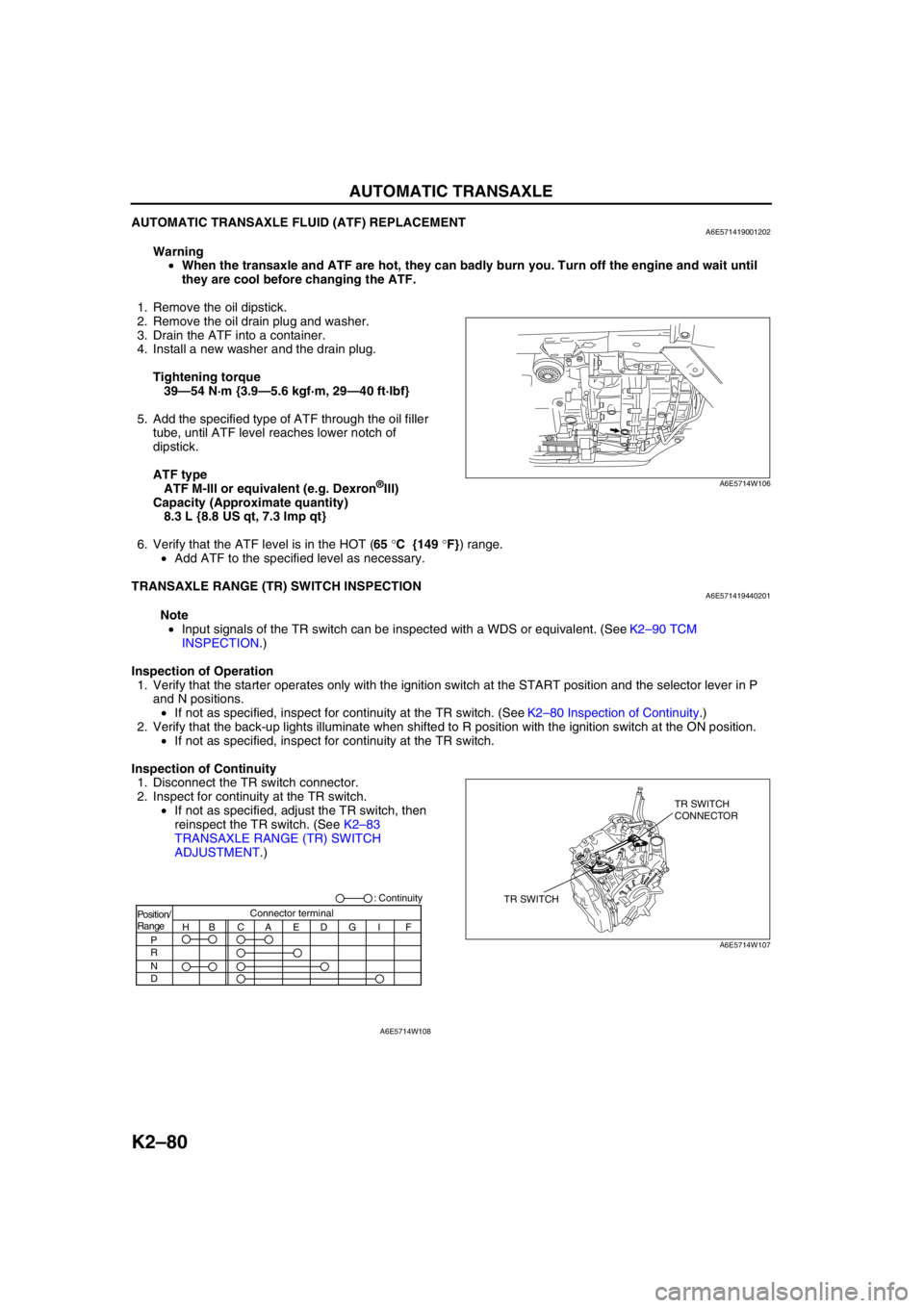
Inspection of Continuity
1. Disconnect the TR switch connector.
2. Inspect for continuity at the TR switch.
•If not as specified, adjust the TR switch, then
reinspect the TR switch. (See K2–83
TRANSAXLE RANGE (TR) SWITCH
ADJUSTMENT.)
A6E5714W106
TR SWITCHTR SWITCH
CONNECTOR
A6E5714W107
Position/
Range
H
P
R
N
DBCAEDGI FConnector terminal: Continuity
A6E5714W108
Page 497 of 909
K2–82
AUTOMATIC TRANSAXLE
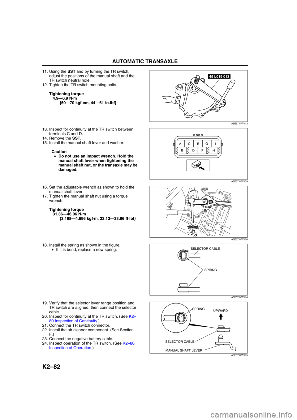
11. Using the SST and by turning the TR switch,
adjust the positions of the manual shaft and the
TR switch neutral hole.
12. Tighten the TR switch mounting bolts.
Tightening torque
4.9—6.9 N·m
{50—70 kgf·cm, 44—61 in·lbf}
13. Inspect for continuity at the TR switch between
terminals C and D.
14. Remove the SST.
15. Install the manual shaft lever and washer.
Caution
•Do not use an impact wrench. Hold the
manual shaft lever when tightening the
manual shaft nut, or the transaxle may be
damaged.
16. Set the adjustable wrench as shown to hold the
manual shaft lever.
17. Tighten the manual shaft nut using a torque
wrench.
Tightening torque
31.36—46.06 N·m
{3.198—4.696 kgf·m, 23.13—33.96 ft·lbf}
18. Install the spring as shown in the figure.
•If it is bend, replace a new spring.
19. Verify that the selector lever range position and
TR switch are aligned, then connect the selector
cable.
20. Inspect for continuity at the TR switch. (See K2–
80 Inspection of Continuity.)
21. Connect the TR switch connector.
22. Install the air cleaner component. (See Section
F.)
23. Connect the negative battery cable.
24. Inspect operation of the TR switch. (See K2–80
Inspection of Operation.)
49 L019 013
A6E5714W113
BC AE
DG
I
FH
A6E5714W109
A6E5714W150
SPRING
SELECTOR CABLE
A6E5714W114
SELECTOR CABLE
MANUAL SHAFT LEVERSPRING
UPWARD
A6E5714W115
Page 498 of 909
AUTOMATIC TRANSAXLE
K2–83
K2
End Of SieTRANSAXLE RANGE (TR) SWITCH ADJUSTMENTA6E571419440203
Caution
•Water or foreign objects entering the connector can cause a poor connection or corrosion. Be
sure not to drop water or foreign objects on the connector when disconnecting it.
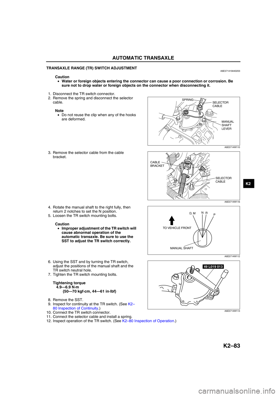
1. Disconnect the TR switch connector.
2. Remove the spring and disconnect the selector
cable.
Note
•Do not reuse the clip when any of the hooks
are deformed.
3. Remove the selector cable from the cable
bracket.
4. Rotate the manual shaft to the right fully, then
return 2 notches to set the N position.
5. Loosen the TR switch mounting bolts.
Caution
•Improper adjustment of the TR switch will
cause abnormal operation of the
automatic transaxle. Be sure to use the
SST to adjust the TR switch correctly.
6. Using the SST and by turning the TR switch,
adjust the positions of the manual shaft and the
TR switch neutral hole.
7. Tighten the TR switch mounting bolts.
Tightening torque
4.9—6.9 N·m
{50—70 kgf·cm, 44—61 in·lbf}
8. Remove the SST.
9. Inspect for continuity at the TR switch. (See K2–
80 Inspection of Continuity.)
10. Connect the TR switch connector.
11. Connect the selector cable and install a spring.
12. Inspect operation of the TR switch. (See K2–80 Inspection of Operation.)
End Of Sie
SPRING
SELECTOR
CABLE
MANUAL
SHAFT
LEVER
A6E5714W110
CABLE
BRACKET
SELECTOR
CABLE
A6E5714W116
TO VEHICLE FRONT
MANUAL SHAFT
D, MN
R
P
A6E5714W112
49 L019 013
A6E5714W113
Page 505 of 909
K2–90
AUTOMATIC TRANSAXLE
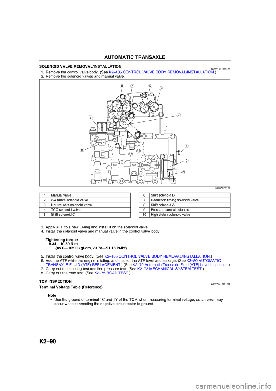
SOLENOID VALVE REMOVAL/INSTALLATIONA6E5714212802031. Remove the control valve body. (See K2–105 CONTROL VALVE BODY REMOVAL/INSTALLATION.)
2. Remove the solenoid valves and manual valve.
.
3. Apply ATF to a new O-ring and install it on the solenoid valve.
4. Install the solenoid valve and manual valve in the control valve body.
Tightening torque
8.34—10.30 N·m
{85.0—105.0 kgf·cm, 73.78—91.13 in·lbf}
5. Install the control valve body. (See K2–105 CONTROL VALVE BODY REMOVAL/INSTALLATION.)
6. Add the ATF while the engine is idling, and inspect the ATF level and leakage. (See K2–80 AUTOMATIC
TRANSAXLE FLUID (ATF) REPLACEMENT.) (See K2–79 Automatic Transaxle Fluid (ATF) Level Inspection.)
7. Carry out the time lag test and line pressure test. (See K2–72 MECHANICAL SYSTEM TEST.)
8. Carry out the road test. (See K2–75 ROAD TEST.)
End Of Sie
TCM INSPECTIONA6E571418901211Terminal Voltage Table (Reference)
Note
•Use the ground of terminal 1C and 1Y of the TCM when measuring terminal voltage, as an error may
occur when connecting the negative circuit tester to ground.
5
44
3
10
687
9
1
2
A6E5714W122
1 Manual valve
2 2-4 brake solenoid valve
3 Neutral shift solenoid valve
4 TCC solenoid valve
5 Shift solenoid C6 Shift solenoid B
7 Reduction timing solenoid valve
8 Shift solenoid A
9 Pressure control solenoid
10 High clutch solenoid valve
Page 514 of 909
AUTOMATIC TRANSAXLE
K2–99
K2
AUTOMATIC TRANSAXLE AND TRANSFER REMOVAL/INSTALLATIONA6E5714190902011. Disconnect the negative battery cable.
2. Remove the battery and battery tray.
3. Remove the aircleaner component. (See Sectin F.)
4. Remove the front tires and splash shield.
5. Remove the under cover.
6. Separate the steering shaft and steering hose. (See N–13 STEERING GEAR AND LINKAGE (4WD)
REMOVAL/INSTALLATION.)
7. Remove the front auto leveling sensor. (See Section T.)
8. Drain the ATF. (See K2–80 AUTOMATIC TRANSAXLE FLUID (ATF) REPLACEMENT.)
Warning
•Improperly jacking a transaxle is dangerous. It can slip off the jack and may cause serious injury.
Caution
•To prevent the torque converter and transaxle from separating, remove the transaxle without
tilting it toward the torque converter.
9. Remove in the order shown in the figure.
10. Install in the reverse order of removal.
11. Adjust the headlight zeroset. (See Section T.)
12. Add ATF to the specified level. (See K2–80 AUTOMATIC TRANSAXLE FLUID (ATF) REPLACEMENT.)
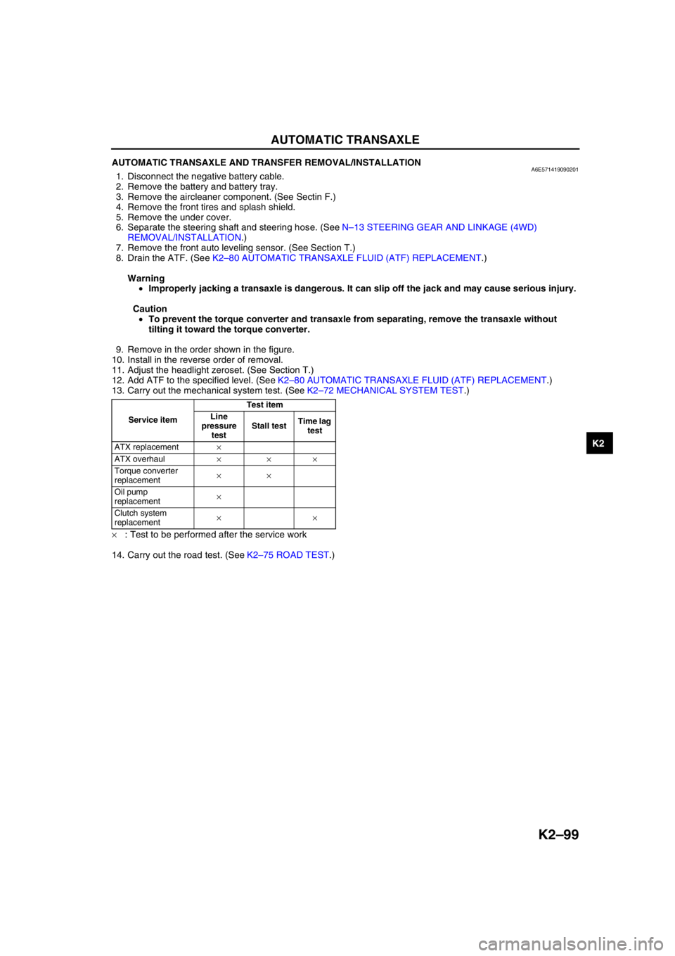
13. Carry out the mechanical system test. (See K2–72 MECHANICAL SYSTEM TEST.)
×: Test to be performed after the service work
14. Carry out the road test. (See K2–75 ROAD TEST.)
Service itemTest item
Line
pressure
testStall testTime lag
test
ATX replacement×
ATX overhaul×××
Torque converter
replacement××
Oil pump
replacement×
Clutch system
replacement××